
NewsNEWCENTER
Featured products
Contact Us
GE DS200EXPSG1ACB Bulk Power Supply Board: Troubleshooting, Fault Diagnosis and Repair Guide
2026-11-06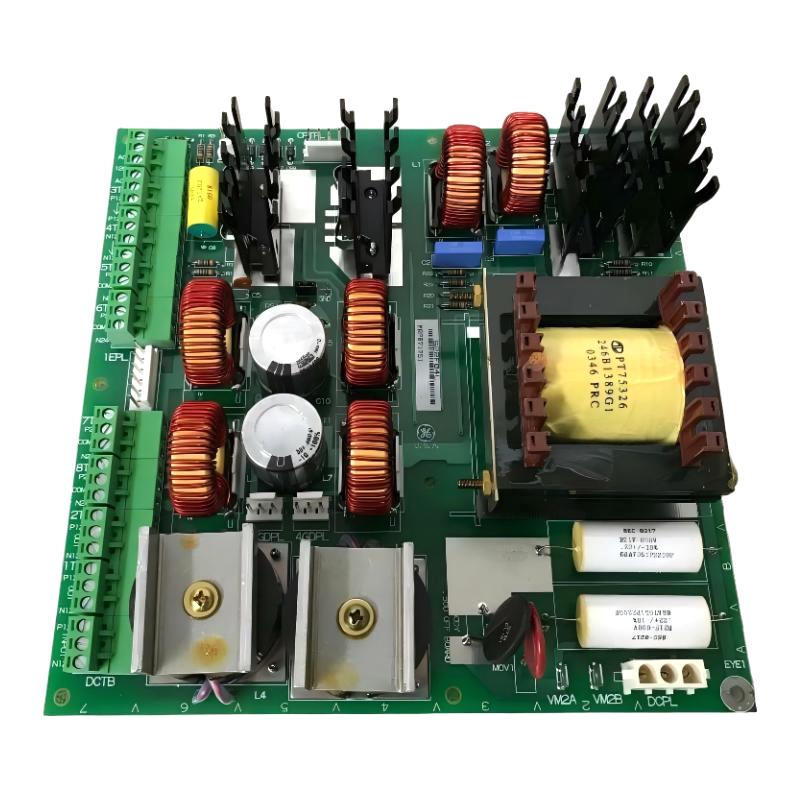
1. Introduction
The GE DS200EXPSG1ACB Bulk Power Supply Board is part of the GE Mark V Speedtronic turbine control system. As a power-related circuit board, it supports the electrical requirements of associated control system circuits. Its reliable operation is important for maintaining stable power distribution and preventing interruptions to turbine control electronics. When the DS200EXPSG1ACB develops a fault, the symptoms may include abnormal board status indications, power-related alarms, unexpected control system behavior, or failures in associated equipment. However, these symptoms do not always indicate that the board itself is defective. Problems with upstream power sources, connectors, fuses, wiring, or connected circuits can produce similar symptoms. This guide provides a systematic approach to troubleshooting the DS200EXPSG1ACB, including visual inspection, fuse checks, connector diagnosis, status LED evaluation, replacement considerations, and preventive maintenance.
2. Product Identification and Main Features
Before troubleshooting, confirm the complete board identification and revision information.
| Parameter | Specification |
|---|---|
| Manufacturer | General Electric (GE) |
| Model | DS200EXPSG1ACB |
| Product Type | Bulk Power Supply Board |
| System | GE Mark V Speedtronic |
| Functional Acronym | EXPS |
| Functional Revision 1 | A |
| Functional Revision 2 | C |
| Artwork Revision | B |
| Connectors | Three 9-pin connectors |
| Fuses | Three |
| Status Indicator | Green LED |
| Other Features | Reset button, test points, JP1 jumper |
| Reference Manual | GEI-100168 |
The complete part number and revision information are important when comparing a suspected faulty board with a replacement. Similar DS200EXPSG1 variants should not be considered interchangeable without confirming their electrical and system compatibility.
3. Common Fault Symptoms and Possible Causes
The following table summarizes common symptoms that may occur during operation or maintenance of the DS200EXPSG1ACB.
| Fault Symptom | Possible Cause | Recommended Diagnostic Action |
|---|---|---|
| Green LED remains off | Missing input power, blown fuse, connector problem, or board fault | Check the approved power path and fuse condition |
| Power-related system alarm | Abnormal supply condition or associated circuit fault | Review system diagnostics and documented test points |
| Intermittent system behavior | Loose connectors, unstable upstream power, or intermittent circuit fault | Inspect connectors and power distribution |
| One or more fuses are blown | Overcurrent, short circuit, wiring fault, or failed component | Identify the underlying cause before fuse replacement |
| Board does not operate after replacement | Incorrect replacement revision, wiring error, or external system fault | Verify part number, connector positions, and system compatibility |
| Repeated failure after startup | Persistent external electrical fault or defective replacement board | Investigate the complete power circuit |
| Abnormal readings at test points | Supply problem, connected circuit fault, or board malfunction | Compare measurements with the exact documented limits |
These symptoms are diagnostic starting points rather than definitive fault codes. A complete assessment should include the board, associated wiring, upstream power source, and receiving control equipment.
4. Safety Precautions Before Troubleshooting
The DS200EXPSG1ACB is installed in a turbine control system, where incorrect maintenance can affect control availability and plant safety. Troubleshooting must be performed by qualified personnel. Before inspection or removal:
- Follow the approved turbine shutdown and maintenance procedure.
- Isolate all relevant electrical power sources.
- Apply lockout/tagout requirements.
- Verify the absence of hazardous voltage using an appropriately rated instrument.
- Allow stored electrical energy to discharge according to system instructions.
- Use ESD protection when handling the PCB.
- Do not insert, remove, or reconnect the board while energized unless an explicitly approved procedure authorizes the operation.
Do not bypass fuses, defeat protective devices, or modify board circuitry to keep a faulty system operating. If the equipment shows signs of smoke, burning, severe overheating, or damaged insulation, isolate it and follow the site’s electrical incident procedure.
5. Step-by-Step Troubleshooting Procedure
5.1 Step 1: Confirm the Fault and Collect System Information
Begin by identifying the exact symptom and determining when it occurs. Record:
- Complete board part number and revision.
- Board installation location.
- Green LED condition.
- Relevant Mark V system alarms.
- Whether the problem occurs during startup or normal operation.
- Recent board replacement or maintenance activities.
- Any changes to connected wiring or power distribution.
Determine whether the problem affects only the DS200EXPSG1ACB or also affects other boards and control system functions. A fault affecting several devices may indicate an upstream supply or shared distribution problem.
5.2 Step 2: Perform a Visual Inspection
With the equipment safely isolated, inspect the board and its surrounding installation. Look for:
- Discoloration around components or fuse holders.
- Cracked or damaged PCB material.
- Burn marks or signs of overheating.
- Corrosion or contamination.
- Loose or damaged connector pins.
- Damaged cable insulation.
- Evidence of previous unauthorized repairs.
Pay particular attention to the three 9-pin connectors and the three fuse positions. Physical damage around these areas may indicate a connection or electrical stress problem. Do not return a visibly damaged board to service without appropriate evaluation.
5.3 Step 3: Check the Incoming Power Path
A board that does not start may be receiving no power or an incorrect supply condition. Check the upstream power source and associated distribution circuit according to the system wiring documentation. Investigate:
- Upstream protective device status.
- Power source availability.
- Loose or damaged wiring.
- Connector seating.
- Abnormal supply conditions.
- Signs of overheating at connection points.
Use only the documented measurement points and specified voltage ranges. Do not assume input voltage values or connector pin assignments based on another DS200 board. If the upstream supply is outside its permitted range, correct that problem before evaluating the board itself.
5.4 Step 4: Inspect the Three Fuses
The DS200EXPSG1ACB includes three fuses. A blown fuse can interrupt an electrical path and prevent the associated circuit from operating. Fuse inspection should be performed only after the relevant power sources have been isolated and the absence of voltage has been verified. Check for:
- Visible fuse element damage, where applicable.
- Discoloration or overheating around the fuse holder.
- Loose or damaged fuse contacts.
- Incorrect fuse type or rating from previous maintenance.
Where visual inspection is insufficient, use an approved continuity test procedure with the fuse safely isolated. A blown fuse should never be replaced without investigating why it opened. Possible causes include a downstream short circuit, abnormal current demand, wiring damage, or a failed component. Always use the exact specified fuse type and rating. Never install a higher-rated fuse or bridge a fuse holder.
5.5 Step 5: Inspect the Three 9-Pin Connectors
Poor connector contact can cause intermittent operation or prevent the board from receiving or distributing power correctly. Check each connector for:
- Correct position and orientation.
- Fully engaged connector housing.
- Bent, damaged, or contaminated pins.
- Loose cable termination.
- Discoloration or heat damage.
- Mechanical strain on the connected wiring.
Compare the connector arrangement with the original installation records and the applicable system drawing. Do not interchange the three connectors based on physical similarity. Their assignments must be confirmed from the correct documentation.
5.6 Step 6: Evaluate the Green Status LED
The green LED provides a useful visual indication of board status. Available product information describes the LED as illuminated when the board has passed its startup diagnostic checks and is operating normally. Use the following diagnostic approach:
| LED Condition | Possible Interpretation | Recommended Action |
|---|---|---|
| Green LED illuminated | Board has completed its startup checks according to available product information | Continue with system-level diagnostic checks |
| Green LED off | Missing power, fuse problem, connector fault, or board malfunction | Check the documented power path, fuses, and connections |
| LED behavior is intermittent | Possible unstable supply or connection problem | Investigate upstream power and connector condition |
The LED should not be used as the only basis for determining board health. Confirm the condition through the approved electrical checks and system diagnostics.
5.7 Step 7: Check the Test Points
The board includes test points intended to support diagnostic measurements. Use the test-point assignments and expected values specified in GEI-100168 or the applicable system documentation. Before testing:
- Confirm the correct board revision.
- Identify the approved test point.
- Verify the required instrument type and measurement range.
- Follow the documented safety procedure.
- Compare the result with the specified tolerance.
Do not probe unidentified points or apply an external voltage to a test point. Incorrect measurements can damage the board or create an electrical hazard.
5.8 Step 8: Review the JP1 Jumper
The DS200EXPSG1ACB includes a JP1 jumper identified as a manufacturing-test configuration feature. JP1 should not be treated as a routine user configuration switch. Do not move, remove, or alter it during ordinary troubleshooting. If the jumper appears to be missing or in a different position from the documented original configuration, compare it with the applicable board documentation and maintenance records. Any correction should be performed only under an authorized service procedure.
6. Troubleshooting Specific Fault Conditions
6.1 Green LED Does Not Illuminate
If the green LED remains off after startup, investigate the power path before deciding that the PCB has failed. Recommended checks:
- Confirm that the system power source is available.
- Check the upstream protective devices.
- Inspect the three fuses using the approved procedure.
- Verify that all three 9-pin connectors are correctly seated.
- Review the relevant power-related system alarms.
- Use documented test points to evaluate the electrical condition.
If the documented input conditions are correct but the board still fails its startup checks, the board may require specialist testing or replacement.
6.2 One or More Fuses Keep Blowing
A fuse that repeatedly opens indicates that the underlying electrical problem has not been resolved. Potential causes include:
- Short circuit in an associated wiring branch.
- Damaged cable insulation.
- Defective downstream equipment.
- Incorrect fuse type or rating.
- Internal board component failure.
Do not repeatedly replace the fuse and restart the equipment. Identify the source of excessive current before installing another fuse.
6.3 Power-Related Alarms Appear After Startup
Power-related alarms may result from abnormal electrical conditions or a fault in an associated control circuit. Review the system diagnostic records and identify which functions are affected. Compare the observed condition with the expected board behavior and documented electrical measurements. If other boards show similar symptoms, investigate shared power distribution and upstream supply conditions.
6.4 Intermittent Operation During Normal Running
Intermittent faults can be difficult to reproduce during routine maintenance. Possible causes include:
- Loose connector contacts.
- Intermittent wiring connections.
- Unstable upstream power.
- Thermal stress.
- Damaged PCB tracks or solder joints.
Review event logs and maintenance records to identify patterns. If the fault occurs after the equipment reaches operating temperature, evaluate thermal conditions and inspect for heat-related damage during a safe shutdown. Do not attempt to move or press connectors while the system is energized as a diagnostic shortcut.
6.5 Replacement Board Does Not Operate Normally
If a replacement DS200EXPSG1ACB does not restore normal operation, check:
- Complete part number and revision compatibility.
- Correct connector positions.
- Correct upstream power conditions.
- Fuse type and condition.
- Associated wiring and downstream circuit condition.
- System diagnostics after startup.
A replacement board may be defective, but incorrect installation or an unresolved external fault must be ruled out first.
7. Board Replacement and Recovery
If diagnostic results indicate that the DS200EXPSG1ACB is defective, replacement should follow the approved Mark V maintenance procedure.
7.1 Verify the Replacement Board
Confirm that the replacement matches the required part number and hardware revision. Check the functional revision and artwork revision rather than relying on the EXPS family designation alone. Inspect the replacement board for physical damage and confirm that its connectors, fuses, and other visible components are in acceptable condition.
7.2 Remove the Faulty Board
Shut down the affected equipment and isolate the relevant power sources. Verify that the circuit is de-energized before disconnecting the board. Record the three connector positions and any relevant installation details. Remove the board carefully and place it in ESD-protective packaging.
7.3 Install the Replacement
Inspect the mounting location and connectors. Install the replacement board in the designated position and reconnect each connector according to the approved drawings. Confirm that the board is properly seated and secured. Do not alter JP1 or replace fuses with unverified alternatives.
7.4 Perform Post-Replacement Checks
After installation, restore power according to the approved startup procedure. Verify:
- Normal board status indication.
- Correct fuse condition.
- Stable electrical conditions at documented test points.
- Absence of recurring power-related alarms.
- Normal operation of associated control system circuits.
The equipment should be returned to service only after the required system-level checks have been completed and accepted by the responsible personnel.
8. Repair and Maintenance Considerations
The DS200EXPSG1ACB is a complex electronic circuit board. Component-level repair should only be performed by qualified specialists using appropriate diagnostic equipment and authorized procedures. Potential repair assessment areas include:
- Fuse holders and electrical contacts.
- Damaged connectors.
- PCB tracks and solder joints.
- Components showing signs of overheating.
- Corrosion or contamination.
Do not attempt unauthorized modifications, jumper changes, or circuit redesign. Such work may affect the board’s electrical characteristics and reliability. For critical turbine control applications, replacement with a verified compatible board may be more appropriate than an undocumented repair.
9. Preventive Maintenance Recommendations
A planned inspection program can help reduce unexpected board failures.
| Maintenance Item | Recommended Inspection | Maintenance Objective |
|---|---|---|
| Board condition | Check for visible damage and overheating | Identify deterioration early |
| Three 9-pin connectors | Inspect contact condition and seating | Prevent intermittent electrical connections |
| Three fuses | Check according to the approved maintenance procedure | Identify protection-related faults |
| Green LED | Observe during normal startup checks | Monitor board status indication |
| Test points | Measure only when required by documented procedures | Support electrical condition assessment |
| JP1 jumper | Confirm its documented configuration without unnecessary adjustment | Avoid unintended changes |
| System alarms | Review power-related diagnostic history | Identify recurring problems |
Maintenance frequency should be determined by the turbine operating environment, equipment criticality, and site maintenance policy.
10. Frequently Asked Questions
What are the common symptoms of a faulty DS200EXPSG1ACB?
Common symptoms include an unlit green status LED, power-related alarms, abnormal electrical measurements, repeated fuse failures, and intermittent behavior in associated control circuits. These symptoms can also originate from external wiring or upstream power problems.
How many fuses are installed on the DS200EXPSG1ACB?
The board is identified as having three fuses. Their individual ratings and circuit assignments should be confirmed using the correct board documentation.
What does an unlit green LED mean?
An unlit green LED may indicate missing power, a fuse problem, an improperly seated connector, or an internal board fault. Engineers should check the complete power path and relevant diagnostics before concluding that the PCB has failed.
Can the JP1 jumper be adjusted during troubleshooting?
JP1 is identified as a manufacturing-test configuration feature. It should not be changed during routine troubleshooting unless an authorized service procedure specifically requires it.
Why does the replacement board fail again after installation?
Repeated failure may indicate an unresolved external electrical fault, incorrect replacement revision, wiring error, or defective replacement hardware. Check the entire power distribution circuit before installing another board.
Can the DS200EXPSG1ACB be repaired?
Specialist repair may be possible depending on the fault and the availability of authorized service procedures. Component-level work should be performed only by qualified technicians using appropriate equipment and verified technical information.
What documentation should be used for troubleshooting?
GEI-100168 is identified as the relevant reference manual for the EXPS bulk power supply board family. Engineers should also consult the applicable Mark V system drawings and maintenance procedures for the installed hardware revision.
11. Conclusion
The GE DS200EXPSG1ACB Bulk Power Supply Board is an important component in the GE Mark V turbine control system. Troubleshooting should focus on the complete electrical path, including the upstream power source, three fuses, three 9-pin connectors, board status indication, documented test points, and associated control circuits. A systematic diagnosis helps distinguish an internal PCB fault from external wiring or power distribution problems. Correct revision verification, careful fuse inspection, and controlled replacement procedures are essential for maintaining system reliability.
Technical Summary
The DS200EXPSG1ACB is a GE Mark V EXPS Bulk Power Supply Board with functional revisions A and C and artwork revision B. It includes three 9-pin connectors, three fuses, a green LED, a reset button, test points, and a JP1 manufacturing-test jumper. Troubleshooting should follow the applicable GEI-100168 documentation and approved system maintenance procedures. Do not modify JP1, bypass fuse protection, or assume electrical ratings and connector assignments without verified documentation.