
NewsNEWCENTER
Featured products
Contact Us
GE DS200EXPSG1ACB Bulk Power Supply Board: Installation, Setup and Commissioning Guide
2026-11-06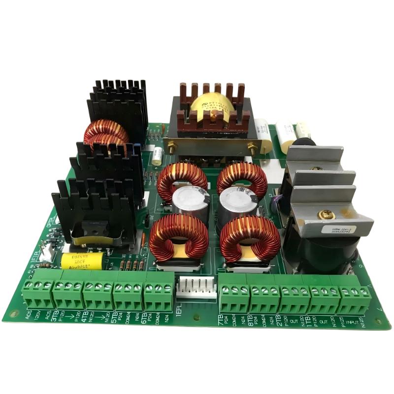
1. Product Overview
The GE DS200EXPSG1ACB is a Bulk Power Supply Board designed for the GE Mark V Speedtronic turbine control system. It belongs to the DS200 circuit board family and is identified by the functional acronym EXPS. The board plays an important role in the power supply architecture of the Mark V control system. It supports the distribution and conditioning of electrical power required by associated control system circuits. Stable power is essential for reliable operation of turbine control electronics, monitoring functions, and related system components. The DS200EXPSG1ACB is a revised version within the DS200EXPSG1 board family. Its complete identification includes functional revisions A and C, together with artwork revision B. These revision details are important when selecting a replacement because similar-looking boards may have different hardware configurations. The board includes three 9-pin connectors, three fuses, a green status LED, a reset button, test points, and a JP1 jumper. Installation and commissioning must follow the applicable GE documentation, particularly manual GEI-100168. This guide covers preparation, replacement, installation checks, startup verification, and maintenance considerations for the DS200EXPSG1ACB.
2. Technical Specifications
| Parameter | Specification |
|---|---|
| Manufacturer | General Electric (GE) |
| Model | DS200EXPSG1ACB |
| Product Type | Bulk Power Supply Board |
| Product Series | Mark V DS200 |
| Functional Acronym | EXPS |
| Functional Revision 1 | A |
| Functional Revision 2 | C |
| Artwork Revision | B |
| Board Type | Printed Circuit Board (PCB) |
| Connectors | Three 9-pin connectors |
| Fuses | Three |
| Status Indicator | Green LED |
| Other Board Features | Reset button, test points, JP1 jumper |
| Reference Manual | GEI-100168 |
| System Application | GE Mark V turbine control system |
The exact electrical input and output ratings, connector assignments, fuse ratings, and test-point values must be obtained from the applicable GE documentation for the installed system. Do not infer these values from the board’s appearance or from specifications belonging to another revision.
3. Main Functions and Board Features
3.1 Bulk Power Supply Function
The DS200EXPSG1ACB forms part of the power supply architecture in the GE Mark V control system. Its role is to support the electrical power requirements of associated control circuits. A stable power supply helps prevent abnormal operating conditions such as electronic circuit resets, unstable control signals, and unexpected interruptions. The board must therefore operate within the electrical and environmental limits established for the complete control system.
3.2 Three 9-Pin Connectors
The board has three 9-pin connectors that provide electrical interfaces within the designated system configuration. During installation, each connector must be returned to its correct position. Connector assignments should be identified from the original wiring arrangement and the applicable board documentation. Do not interchange connectors based only on their physical similarity. Incorrect connections can cause power distribution problems or damage associated equipment.
3.3 Fuse Protection
The DS200EXPSG1ACB incorporates three fuses as part of its circuit protection arrangement. The condition of each fuse should be checked when the board exhibits abnormal power behavior. A blown fuse may indicate an electrical fault, excessive current, wiring problem, or failure in a connected circuit. Always use the specified fuse type and rating. Installing a fuse with a higher rating or bypassing fuse protection can create additional equipment and safety risks.
3.4 Green Status LED
A green LED is provided for board status indication. Available product information describes the LED as illuminated when the board has passed its startup diagnostic checks and is operating normally. If the LED remains off, engineers should investigate the incoming power conditions, fuse status, connector installation, and board diagnostics. An unlit LED should not automatically be interpreted as proof of an internal board failure.
3.5 Reset Button and Test Points
The board includes a reset button and multiple test points. These features support maintenance and diagnostic activities. The reset button should only be operated according to the applicable GE procedure. Unnecessary resets can interrupt control functions or make it more difficult to identify the original fault. Test points must be used only with the measurement procedures and electrical values specified in the correct documentation.
3.6 JP1 Jumper
The DS200EXPSG1ACB includes a jumper identified as JP1. Available product documentation describes this jumper as a manufacturing-test configuration feature. It should not be moved or adjusted during routine installation, maintenance, or troubleshooting. Keep the jumper in its original documented position unless an authorized GE service procedure explicitly instructs otherwise.
4. Installation Preparation
4.1 Verify the Complete Part Number
Before installing the board, check its complete identification:
- DS200EXPSG1ACB.
- Functional revision A.
- Functional revision C.
- Artwork revision B.
The complete part number is important because the DS200EXPSG1 family includes multiple hardware revisions and related versions. Do not assume that every board with an EXPS designation is automatically interchangeable.
4.2 Confirm System Compatibility
Check that the receiving Mark V system is designed to accept the DS200EXPSG1ACB. Verify the following:
- Correct board location and rack arrangement.
- Compatible connector configuration.
- Correct revision requirements.
- Approved electrical interfaces.
- Applicable system power distribution arrangement.
For replacement projects, compare the new board with the original installed unit and consult the system hardware documentation before proceeding.
4.3 Inspect the Replacement Board
Before installation, inspect the PCB under suitable lighting. Look for:
- Cracked or damaged circuit board material.
- Damaged connector pins or housings.
- Loose components.
- Discolored areas or signs of overheating.
- Damaged fuses or fuse holders.
- Corrosion or contamination.
- Evidence of previous unauthorized repair.
Do not install a board that shows significant physical damage or signs of electrical overheating without further evaluation.
4.4 Prepare the Work Area
The installation area should be clean, dry, and free from conductive debris. Use an ESD-safe work surface and appropriate grounding equipment when handling the circuit board. Avoid touching connector contacts or exposed electronic components unnecessarily. Keep the replacement board in suitable protective packaging until it is ready to be installed.
5. Safety Precautions
The DS200EXPSG1ACB is part of a turbine control power supply system. Incorrect installation can affect control equipment and may create electrical and operational hazards. Only qualified personnel should perform installation and maintenance. Before handling the board:
- Follow the approved turbine shutdown and maintenance procedure.
- Isolate all relevant electrical power sources.
- Apply lockout/tagout requirements.
- Verify that hazardous voltage is absent at the designated points.
- Allow stored electrical energy to discharge according to system instructions.
- Use suitable insulated tools and ESD protection.
- Do not remove or insert the board while energized unless an explicitly approved procedure authorizes the operation.
A turbine control board should not be treated as an ordinary plug-in electronic component. Before removing it, assess the effect on power distribution, control availability, protection functions, and plant operating conditions.
6. GE DS200EXPSG1ACB Installation Procedure
Step 1: Record the Existing Board Configuration
Before removing the original board, record its complete part number, revision information, mounting position, connector locations, and visible status indications. Take suitable maintenance photographs where permitted by the plant procedure. These records can help prevent connector interchange and simplify restoration.
Step 2: Isolate the Relevant Power Sources
Shut down the affected equipment according to the approved system procedure. Isolate the relevant electrical sources and verify the absence of hazardous voltage. Do not rely only on a control system shutdown command. Electrical isolation and verification must be completed before handling the PCB.
Step 3: Disconnect the Board Connectors
Identify the three 9-pin connectors and their original positions. Disconnect them carefully using the approved method. Avoid pulling on the cable itself. Inspect connector housings and contacts for damage, contamination, or signs of overheating. Keep the connectors identified throughout the replacement process.
Step 4: Remove the Original Board
Release the board’s mechanical retention arrangement according to the applicable equipment instructions. Remove the PCB carefully, avoiding contact with adjacent components and exposed connectors. Place the removed board in an ESD-protective container for inspection or repair evaluation.
Step 5: Inspect the Board Mounting Position
Before installing the replacement, inspect the receiving position for:
- Damaged mounting points.
- Contaminated connectors.
- Loose hardware.
- Foreign objects or conductive debris.
- Signs of overheating.
If the original board failed because of an external electrical fault, investigate and correct that fault before installing the replacement. Otherwise, the new board may experience the same problem.
Step 6: Install the Replacement Board
Confirm the replacement part number and revision again. Align the DS200EXPSG1ACB with the designated mounting position and insert it carefully. Make sure the PCB is properly seated and secured. Do not force the board into position or use excessive pressure on its edges.
Step 7: Reconnect the Electrical Interfaces
Reconnect the three 9-pin connectors according to the original configuration and applicable wiring documentation. Check that:
- Each connector is installed in its correct position.
- Connector housings are fully engaged.
- No pins are bent or damaged.
- Cables are not trapped or under mechanical stress.
- All connections match the approved system drawings.
Do not alter JP1 during this procedure. It is identified as a manufacturing-test jumper rather than a routine user configuration point.
Step 8: Complete the Pre-Energization Inspection
Before restoring power, inspect the board and its surrounding installation. Confirm that the board is secure, connectors are correctly seated, and no tools or foreign objects remain in the equipment. Verify that all maintenance steps have been completed and that the system is ready for controlled startup.
7. Startup and Commissioning
7.1 Restore Power According to the System Procedure
Restore power only after the installation has been checked and the responsible personnel have authorized startup. Follow the approved Mark V power-up sequence. Do not apply an arbitrary voltage to the board or attempt to energize it outside its designated system arrangement.
7.2 Observe the Green Status LED
During startup, observe the board’s green LED. A normal green indication is associated with successful startup diagnostic checks according to available product information. If the LED does not illuminate, stop and investigate the condition. Check the incoming supply, fuse condition, connector seating, and related system diagnostics before deciding whether the board is defective.
7.3 Check the Fuse Condition
If power-related abnormalities remain, inspect the three fuses using the procedure specified by the applicable manual. Fuse inspection and replacement should be carried out only after the relevant circuits have been isolated and verified as de-energized. Never replace a fuse with an unverified rating. A repeatedly blown fuse is an indication that the underlying electrical fault must be identified.
7.4 Verify System Power Distribution
Confirm that the associated control system circuits receive the expected power under the specified operating conditions. Use only the designated test points and measurement procedures described in GEI-100168 or the applicable system documentation. Do not assume that test-point voltages or connector pin assignments are the same across different revisions.
7.5 Check Related Control System Diagnostics
After the board starts successfully, review the Mark V system diagnostic information. Check for:
- Power-related diagnostic alarms.
- Abnormal board status indications.
- Unexpected resets.
- Faults affecting associated control circuits.
- Unusual behavior in connected system components.
A normal LED indication alone does not confirm that every connected system function is operating correctly. Complete the required system-level checks before returning the equipment to normal service.
7.6 Record Commissioning Results
Document the replacement and startup results for future maintenance. The commissioning record should include:
- Installed board part number and revision.
- Original board identification.
- Installation date and equipment location.
- Connector inspection results.
- Fuse inspection results.
- LED status during startup.
- Relevant diagnostic messages.
- Any corrective actions performed.
8. Integration with the GE Mark V Control System
The DS200EXPSG1ACB is designed for use within the GE Mark V turbine control platform. Its operation depends on the correct interaction between the board, its power sources, associated control circuits, and the wider system architecture. When integrating or replacing this board, engineers should evaluate the complete electrical arrangement rather than treating the PCB as an isolated component. Important considerations include:
- Compatibility with the installed Mark V hardware configuration.
- Correct connector assignments and electrical interfaces.
- Proper condition of upstream power sources.
- Correct fuse specifications and protection arrangements.
- Stable operation of associated control circuits.
- Consistency between board revisions and system documentation.
The board should not be connected to an unrelated PLC or power distribution system simply because its connectors appear physically compatible. Its electrical interfaces are designed for the specified GE control system application.
9. Maintenance and Reliability Recommendations
Routine inspection can help identify developing faults before they cause control system interruptions. Recommended maintenance activities include:
| Inspection Item | Recommended Action | Purpose |
|---|---|---|
| PCB condition | Inspect for physical damage, contamination, and overheating | Identify visible board deterioration |
| Connectors | Inspect the three 9-pin interfaces | Prevent connection-related faults |
| Fuses | Check condition using the approved procedure | Identify protection-related problems |
| Green LED | Observe during startup and normal operation | Review board status indication |
| Test points | Use documented measurement procedures when required | Support electrical diagnosis |
| JP1 jumper | Leave in its documented original position | Avoid unintended configuration changes |
| System diagnostics | Review relevant Mark V alarms and event records | Identify abnormal operating conditions |
Avoid unnecessary removal and reinsertion of the PCB. Repeated handling can increase the risk of connector wear, electrostatic damage, and mechanical stress.
10. Frequently Asked Questions
What is the GE DS200EXPSG1ACB?
The DS200EXPSG1ACB is a Bulk Power Supply Board used in the GE Mark V Speedtronic turbine control system. Its functional acronym is EXPS.
What are the main components on the DS200EXPSG1ACB?
The board includes three fuses, three 9-pin connectors, a green status LED, a reset button, multiple test points, and a JP1 jumper.
What does the green LED indicate?
Available product information describes the green LED as an indication that the board has passed its startup diagnostic checks and is operating normally. An unlit LED requires further inspection of the power supply, fuses, connectors, and board condition.
What is the function of the JP1 jumper?
JP1 is identified as a manufacturing-test jumper. It should not be adjusted during normal installation or maintenance unless an authorized service procedure specifically requires it.
Which manual is relevant to the DS200EXPSG1ACB?
GEI-100168 is identified as the relevant reference manual for the EXPS bulk power supply board family. The exact revision and applicable system instructions should be confirmed before maintenance.
Can the DS200EXPSG1ACB be replaced by another DS200EXPSG1 board?
Not automatically. Check the complete part number, functional revisions, artwork revision, connector arrangement, and system compatibility before selecting a replacement.
Why might the green LED remain off after installation?
Possible causes include missing or incorrect input power, a blown fuse, an improperly seated connector, an external circuit fault, or an internal board problem. Follow the documented diagnostic procedure before replacing the board again.
11. Conclusion
The GE DS200EXPSG1ACB Bulk Power Supply Board is an important component in the Mark V turbine control system power architecture. Its three 9-pin connectors, fuse protection, green status LED, reset button, and diagnostic test points support its role in the control system. Reliable installation requires careful revision verification, correct connector identification, appropriate electrical isolation, and adherence to the applicable GE maintenance instructions. During commissioning, engineers should inspect the LED indication, verify the fuse condition when necessary, review system diagnostics, and confirm stable operation of the associated control circuits.
Technical Summary
The DS200EXPSG1ACB is a GE Mark V EXPS Bulk Power Supply Board with functional revisions A and C and artwork revision B. It features three 9-pin connectors, three fuses, a green LED, a reset button, test points, and a JP1 manufacturing-test jumper. For installation and commissioning, use the applicable GEI-100168 documentation and the exact system wiring and maintenance procedures. Never modify the jumper or assume connector pin assignments and electrical ratings without documentation.