
NewsNEWCENTER
Featured products

Contact Us
GE 531X111PSHARG3 MCF/Power Supply Card Installation and Commissioning Guide
2026-10-21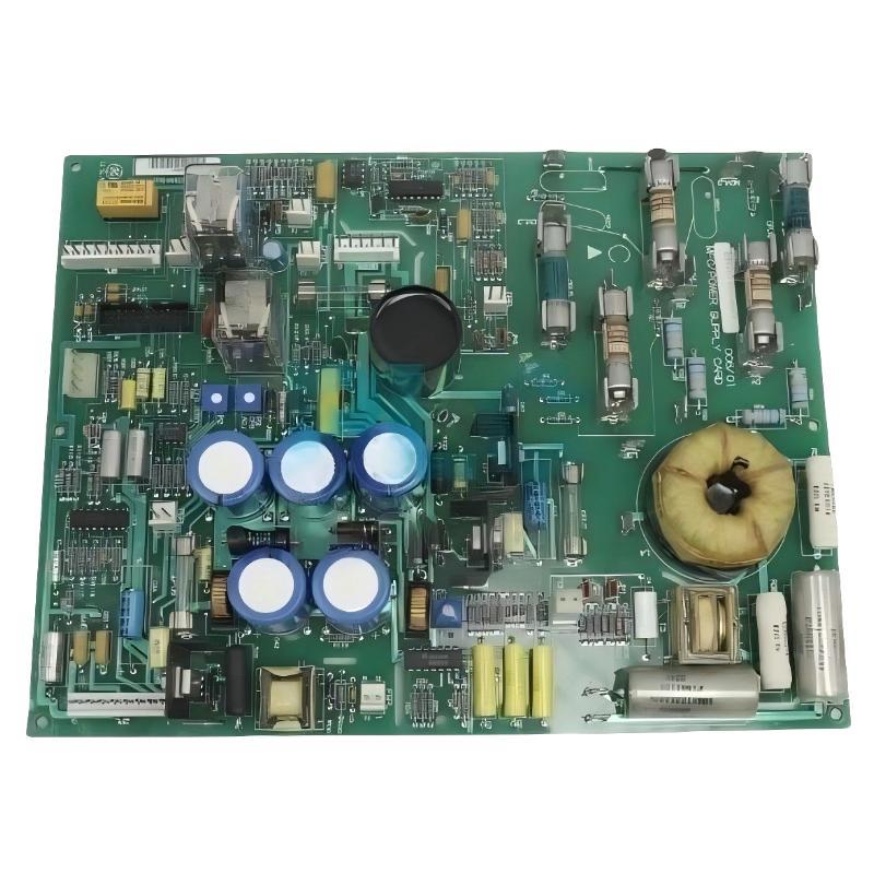
The GE 531X111PSHARG3 MCF/Power Supply Card is a motor field control and power supply board used in compatible GE industrial drive and excitation systems. It provides essential DC power for drive electronics and supports motor field circuitry. Correct installation is important for maintaining reliable power distribution, field-control operation, and system protection.
This guide covers installation preparation, compatibility checks, safe board replacement, wiring verification, commissioning, and post-installation testing. Because GE 531X boards were produced in different revisions and configurations, the exact equipment manual and board identification must be checked before installation. This guide is intended for qualified industrial electrical and drive-service personnel.
Table of Contents
- 1. Product Overview
- 2. Main Functions and Features
- 3. Installation Preparation
- 4. Electrical Safety Requirements
- 5. Compatibility and Revision Verification
- 6. Removing the Existing Board
- 7. Installing the GE 531X111PSHARG3
- 8. Wiring and Connection Inspection
- 9. Commissioning and Functional Testing
- 10. Integration with the Drive System
- 11. Maintenance Recommendations
- 12. Technical FAQs
- 13. Technical Summary
1. Product Overview
The GE 531X111PSHARG3 is part of the GE 531X replacement board family and is identified as a motor field control and power supply board. It is used in compatible legacy GE drive and excitation equipment where auxiliary power and motor field-control functions are required.
The board generates several DC supply rails for the host equipment and incorporates circuitry associated with motor field control. Its documented functions include 5 VDC, 15 VDC, and 24 VDC supplies, an integrated pulse transformer for motor field circuitry, and onboard relays used for drive-status or control functions.
The 531X111PSHARG3 is a specific hardware revision. The suffix matters: boards with similar 531X part numbers may have different component layouts, connections, or application requirements. A physically similar board should not be assumed to be interchangeable without confirming compatibility.
2. Main Functions and Features
2.1 DC power generation
The card supplies the DC voltage rails required by compatible drive electronics. The commonly documented outputs include 5 VDC, 15 VDC, and 24 VDC. These supplies support the host system’s control and auxiliary circuits, according to the design of the particular drive.
2.2 Motor field control support
The board includes an integrated pulse transformer associated with supplying power to motor field circuitry. This function makes the board important to systems where motor excitation or field-current control is part of the drive’s operating process.
2.3 Relay functions
The board incorporates three relays commonly identified as K1, K2, and K3. Their labels and functions are described in the applicable board documentation; commonly documented designations include RUN, MAX, and FAULT. Verify the exact relay assignments and external circuit behavior for the installed system rather than relying on labels alone.
2.4 Adjustment components
The board may include potentiometers and configurable jumpers associated with field scaling and current-feedback calibration. These components are adjustment points, not general-purpose setup controls. Their positions should be recorded before removal, and no adjustment should be changed without the correct commissioning procedure and test equipment.
2.5 G3 revision considerations
The G3 revision is associated with AC-line metal-oxide varistors (MOVs) mounted externally rather than directly on the board. The external surge-protection arrangement must be checked during replacement. Confirm that required external components are present, correctly connected, and suitable for the target equipment before applying power.
3. Installation Preparation
Before beginning installation, confirm that the replacement card is correct for the host drive or excitation system and that the required supporting documentation is available.
3.1 Verify the part number
- Read the complete part number on the existing board, including all suffix characters.
- Confirm that the replacement is GE 531X111PSHARG3 or an explicitly approved equivalent.
- Compare the board revision, component layout, connectors, and mounting arrangement.
- Check whether the replacement requires external MOVs or other components not mounted directly on the board.
- Confirm that the host drive’s documentation lists the board as compatible.
3.2 Prepare tools and materials
- Approved personal protective equipment and electrical safety equipment.
- Insulated hand tools appropriate for the cabinet and terminal hardware.
- A calibrated digital multimeter with suitable voltage ratings.
- ESD protection, such as an approved grounded wrist strap and ESD-safe work surface.
- Equipment-specific installation drawings, wiring diagrams, and commissioning instructions.
- Labels, a camera, and a maintenance record for documenting connections and original settings.
3.3 Record the existing configuration
Before removing the old card, document connector positions, wire identification, jumper locations, potentiometer positions, external surge-protection connections, and visible damage. Capture clear photographs and compare them with the wiring diagram.
Recording the original settings helps restore the intended configuration, but it does not prove that those settings are correct. If the old board was associated with an unresolved drive fault, verify the required settings against the approved engineering documentation.
4. Electrical Safety Requirements
Drive and excitation cabinets can contain hazardous AC and DC voltages. Capacitors may retain energy after the incoming supply is disconnected, and motor field circuits can present additional hazards. Installation must follow the host equipment’s safety procedures.
- Stop the equipment using the approved shutdown procedure.
- Isolate all relevant incoming power sources and auxiliary supplies.
- Apply lockout/tagout in accordance with site requirements.
- Wait for the discharge interval specified by the equipment manufacturer.
- Verify absence of hazardous voltage with an appropriately rated instrument using the site’s approved test method.
- Confirm that connected motor field and external circuits cannot energize the work area unexpectedly.
- Use ESD precautions when handling the printed circuit board.
Never remove, insert, or reconnect the card under power unless the exact equipment documentation explicitly authorizes that procedure. Do not defeat protective interlocks or use an improvised test connection to force the drive to operate.
5. Compatibility and Revision Verification
The GE 531X111PSHARG3 should be installed only in equipment for which the board is specified or formally approved. Similar part numbers may share a general function while differing in circuit configuration, component placement, or application.
Before proceeding, verify the following:
| Verification item | What to confirm |
|---|---|
| Host equipment | Drive or excitation model and the documented board position |
| Part number | Complete 531X111PSHARG3 designation and revision |
| Connector arrangement | Connector type, orientation, and corresponding harness connections |
| Power architecture | Required input supply and expected DC outputs |
| External protection | Required MOVs and their documented connection arrangement |
| Control configuration | Jumper positions, potentiometer settings, and field-feedback requirements |
| Commissioning procedure | Required checks, permitted test conditions, and return-to-service steps |
If any item cannot be confirmed, stop and obtain the correct equipment documentation before connecting the board.
6. Removing the Existing Board
6.1 Confirm isolation
Complete the shutdown and electrical isolation procedure described in Section 4. Confirm that the work area is safe before touching the board, connectors, or associated wiring.
6.2 Document connections
Photograph the installed card from several angles. Record connector positions, harness identification, mounting hardware, jumper locations, potentiometer positions, and any external components associated with the AC input or surge-protection circuit.
6.3 Disconnect and remove
- Label any removable wiring or harnesses that are not uniquely keyed.
- Release connector locks and fasteners using the approved method.
- Pull connectors straight where the design requires it; do not twist or pry against the circuit board.
- Remove the mounting hardware and carefully withdraw the board from its guides or supports.
- Place the removed card in an ESD-safe container for inspection or repair evaluation.
Inspect the surrounding assembly for heat discoloration, damaged insulation, loose hardware, contamination, or signs of arcing. Replacing the card without investigating the cause of the original failure may lead to repeated damage.
7. Installing the GE 531X111PSHARG3
7.1 Inspect the replacement
Before installation, check the replacement board for bent pins, damaged connectors, cracked components, contamination, and shipping damage. Confirm that the full part number and revision match the approved replacement specification.
7.2 Compare configuration settings
Compare the replacement board’s jumpers and adjustment components with the recorded original settings and the host equipment’s approved setup instructions. Do not turn potentiometers simply because their positions differ visually. Some replacement boards may arrive with settings that require application-specific verification.
7.3 Position and secure the board
- Align the board with the intended mounting guides or connector position.
- Insert it evenly without forcing the edge connector or connector pins.
- Confirm that the board is fully seated and correctly oriented.
- Reinstall the specified mounting hardware and secure it according to the equipment procedure.
- Check that the board is stable and that no cables or adjacent components are trapped.
7.4 Reconnect harnesses and wiring
Reconnect each plug and wire according to the documented connector identification and wiring diagram. Confirm that connectors are fully seated and that cable routing does not place mechanical stress on the board. Do not infer pin assignments from connector appearance or from a different 531X board revision.
8. Wiring and Connection Inspection
Connection errors can cause incorrect supply voltages, drive faults, loss of control signals, or damage to the replacement card. Perform a complete inspection before restoring power.
- Check that each connector is connected to its documented destination.
- Verify that terminal polarity and supply connections match the applicable drawings.
- Inspect wire insulation for cuts, pinching, overheating, or deterioration.
- Confirm that required external MOV components are installed and connected according to the G3 configuration.
- Check grounding and bonding connections in accordance with the equipment design.
- Verify that no loose hardware, tools, or conductive debris remain in the cabinet.
- Confirm that jumper settings and calibration adjustments match the approved configuration.
Do not apply generic resistance or continuity tests to semiconductor circuits without an approved procedure. An incorrect test method may damage components or produce misleading results.
9. Commissioning and Functional Testing
Commissioning should proceed in stages. Do not immediately operate the drive at full load after replacing the card.
9.1 Pre-power inspection
Confirm that all connectors are seated, mounting hardware is secure, the cabinet is clear of tools, external protection is correctly installed, and all safety covers are restored as required. An independent check by another qualified technician is recommended for critical equipment.
9.2 Restore power under an approved procedure
Remove lockout/tagout only when authorized and in accordance with the site’s formal procedure. Restore power using the equipment manufacturer’s startup sequence. Monitor for unexpected sounds, odors, smoke, abnormal heating, or protective-device operation. If an abnormal condition occurs, stop the procedure and isolate the equipment safely.
9.3 Verify power outputs
Using the prescribed test points and procedures, verify the required DC supply rails. The board family is documented as providing 5 VDC, 15 VDC, and 24 VDC outputs, but acceptable tolerances and test locations must come from the applicable technical documentation.
Do not probe arbitrary points on an energized board. Measurements must be performed only by qualified personnel with correctly rated instruments and an approved energized-work procedure.
9.4 Verify relay and field-control behavior
Check the documented RUN, MAX, and FAULT relay functions against the host system’s expected status. Verify field-control behavior and feedback signals according to the approved commissioning test. Relay states and field responses must be assessed in the context of the complete drive system.
9.5 Perform a controlled operational test
- Confirm that no unresolved power-supply or control faults remain.
- Complete the drive’s specified no-load or low-risk test where supported by the system design.
- Verify status indications, control feedback, and expected interlock behavior.
- Increase operating demand only in accordance with the approved commissioning procedure.
- Record measured values, observed relay states, alarm history, and any deviations from expected operation.
10. Integration with the Drive System
The 531X111PSHARG3 does not operate independently of the host equipment. Its performance depends on the drive’s power architecture, control electronics, field circuitry, feedback signals, and protective functions.
10.1 Power-system integration
Confirm that the card’s power outputs are appropriate for the intended drive configuration and that downstream circuits operate within their documented requirements. If an output is abnormal, investigate downstream shorts or excessive loads before assuming that the replacement board is defective.
10.2 Motor field and feedback integration
Field control and current-feedback circuits may require calibrated settings. Use the approved test procedure to verify the relationship between measured feedback, expected current, and controller response. Never change calibration settings merely to suppress a fault or force a particular reading.
10.3 Fault and status monitoring
Confirm that the host controller correctly recognizes expected RUN, MAX, and FAULT states where these relay functions are used. Check alarms and interlocks before returning the equipment to automatic operation.
11. Maintenance Recommendations
- Inspect the board and surrounding cabinet for contamination, loose connections, and signs of overheating during scheduled shutdowns.
- Keep a record of the board part number, revision, replacement date, and commissioning measurements.
- Maintain accurate wiring diagrams and photographs of the installed configuration.
- Review recurring drive faults to determine whether the root cause lies in the card, external power, field circuit, or downstream load.
- Keep the cabinet within the environmental limits specified for the host equipment.
- Use approved ESD handling procedures for all spare boards.
- Store replacement cards in suitable protective packaging and inspect them before use.
- Follow the equipment-specific schedule for inspection and calibration of field-feedback circuits.
12. Technical FAQs
What is the GE 531X111PSHARG3 used for?
It is a motor field control and power supply board used in compatible GE industrial drive and excitation systems. It supplies required DC power and supports motor field circuitry.
What DC outputs are associated with this board?
The board is documented as providing 5 VDC, 15 VDC, and 24 VDC supplies. Exact measurement points and acceptable voltage tolerances must be verified against the applicable equipment documentation.
What does the G3 revision mean?
The G3 version is associated with AC-line MOVs mounted externally rather than directly on the board. Confirm the required external components and connections before commissioning.
Can I replace it with another 531X power supply card?
Not without verification. Boards in the same family may differ in revision, circuit arrangement, connector configuration, or application. Confirm compatibility using the complete part number and host equipment documentation.
Should I adjust the potentiometers during installation?
Only when the approved setup or calibration procedure requires it. Record the original positions and use the specified test equipment and adjustment method. Uncontrolled adjustment can affect field control and current-feedback accuracy.
Why might a replacement board fail to restore drive operation?
The underlying fault may involve external power, wiring, external surge protection, downstream loads, field circuitry, or configuration. Check the complete system rather than assuming that the board is the only possible cause.
Can the board be removed while the drive is powered?
Do not remove or insert the board under power unless the exact host equipment documentation explicitly authorizes the procedure. The safe default is to isolate hazardous energy and verify the equipment is safe before handling the board.
13. Technical Summary
The GE 531X111PSHARG3 MCF/Power Supply Card is an important component in compatible GE drive and excitation systems. Its power-generation and motor field-control functions make correct part-number verification, careful installation, and structured commissioning essential to reliable operation.
A successful installation requires confirmation of host-system compatibility, safe isolation, ESD protection, accurate connector restoration, verification of external MOV arrangements, and controlled testing of power outputs and field-control functions. Because the 531X family includes multiple revisions, always use the documentation applicable to the exact board and host equipment.
Following a documented installation and commissioning procedure helps reduce wiring errors, avoid unnecessary board replacement, and restore the drive system to service with greater confidence.