

ProductPRODUCT
Featured products



Contact Us
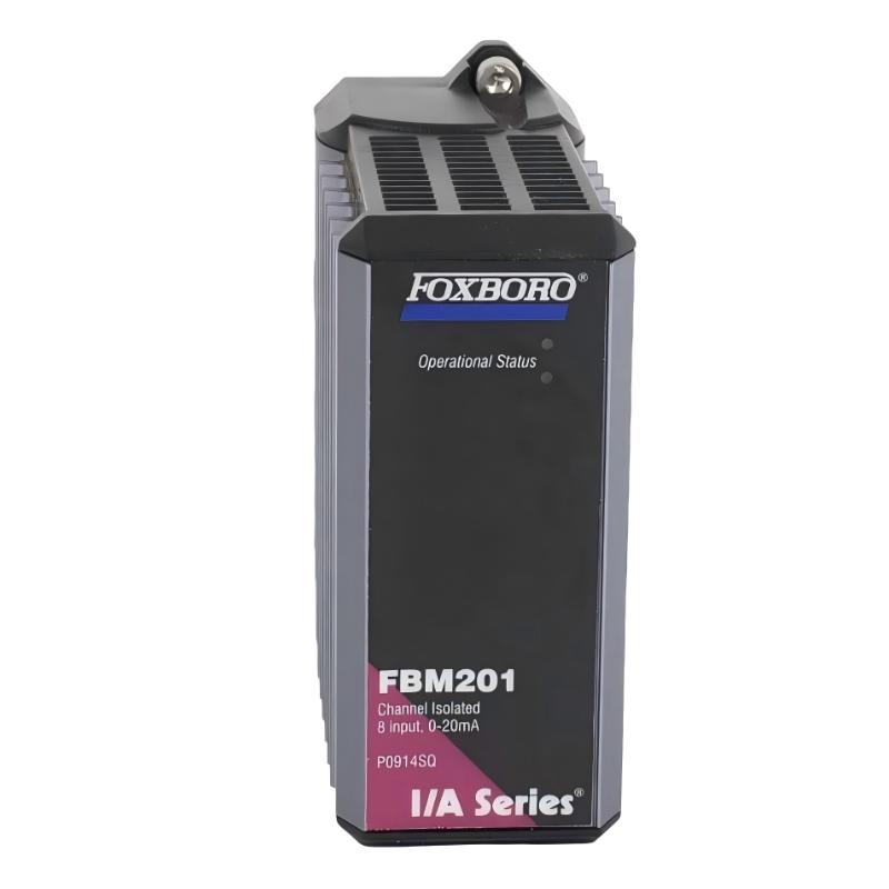
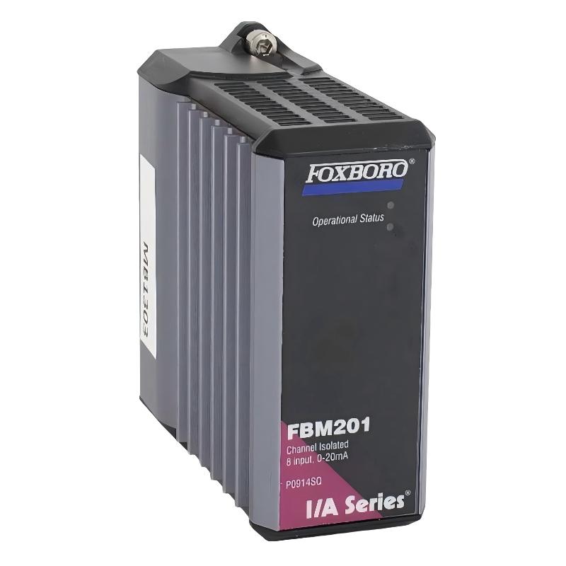
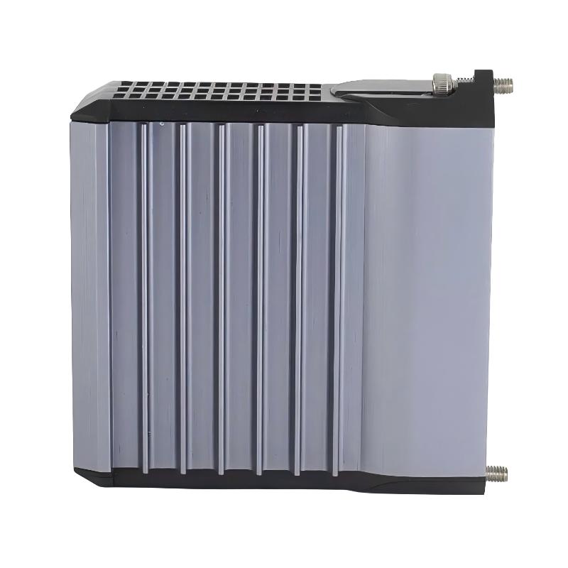
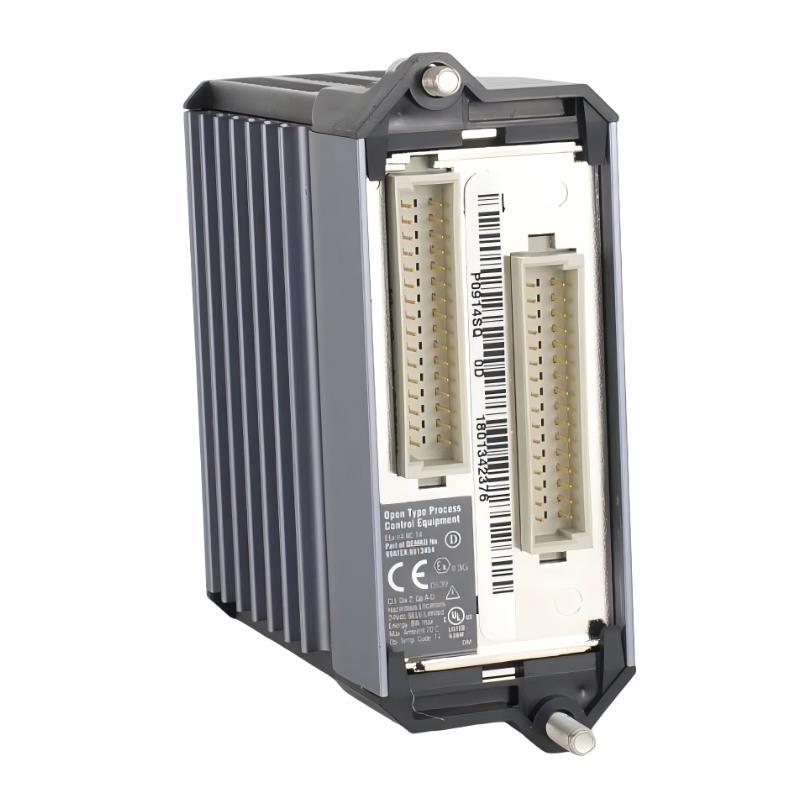
- Foxboro
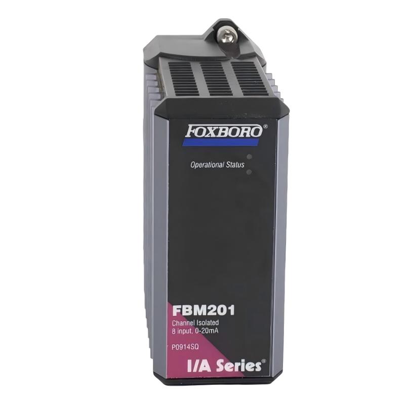
- FBM201 P0914SQ
- Analog Input Interface Module
- USA
- 114 x 45 x 104 mm
- 0.284 kg
- Xiamen, China
- New & In Stock
- T/T, PayPal, Western Union
- 1 Year
- 1-3 Working Days
- DHL, UPS, TNT, FedEx and EMS.
- 24-Hour Service
- COO
- 55
Our advantage

Global Logistics
We have a 10-year logistics and express cooperation agreement, so our products can be shipped to any place in the world.

Brand new and original
Our products are imported in bulk from the place of origin. Because of the cooperative relationship, our products are all original and 100% new.

24-hour service
We provide 7*24 hours service to our customers. We will be there whenever you need us.

Price advantage
All our products are priced very favorably because we have our own warehouse and supply.
| Company Information | |||
| [email protected] | |||
| Mobile | +8615980777398 | ||
| +8615980777398 | |||
| 15980777398 |
Product Overview
The Foxboro FBM201 P0914SQ Analog Input Interface Module is an analog input interface component used in compatible Foxboro distributed control system architectures. It provides an interface between field-side analog instrumentation and the control system, allowing process measurements to be acquired for monitoring, alarm management, process control, and operator visualization.
The FBM201 belongs to the Foxboro Fieldbus Module family. In a typical control architecture, field instruments generate electrical analog signals representing process variables such as pressure, temperature, flow, or level. The interface module receives these signals and makes the corresponding measurement information available to the control system.
The supplied product information is:
- Manufacturer: Foxboro
- Model: FBM201
- Part Number: P0914SQ
- Product Type: Analog Input Interface Module
- Dimensions: 114 × 45 × 104 mm
- Weight: 0.284 kg
- Primary Function: Analog Input Interface
- Application: Industrial DCS / Process Automation
- Installation Type: Modular Control-System I/O
Because field instrumentation can be installed in electrically noisy industrial environments, proper wiring, grounding, shielding, loop integrity, and module installation are important for maintaining reliable analog measurements.
Technical Specifications
| Parameter | Specification |
|---|---|
| Manufacturer | Foxboro |
| Model | FBM201 |
| Part Number | P0914SQ |
| Product Type | Analog Input Interface Module |
| Dimensions | 114 × 45 × 104 mm |
| Weight | 0.284 kg |
| Main Function | Analog Signal Input |
| Application | DCS / Industrial Process Control |
| Installation | Modular I/O System |
| Signal Type | Analog Field Instrument Interface |
| System Role | Field Signal Acquisition |
| Maintenance | Installation / Commissioning / Troubleshooting |
The dimensions and weight above are based on the supplied product information.
Function and Working Principle
The FBM201 provides the interface between field-side analog instrumentation and the Foxboro control system.
A simplified signal path is:
Process
↓
Field Sensor / Transmitter
↓
Field Wiring
↓
FBM201 Analog Input
↓
DCS Processing
↓
Control Strategy
↓
Operator Interface
For example, a pressure transmitter may measure pressure in a process vessel and generate an analog signal. The FBM201 receives the signal and passes the corresponding process information into the control system.
The DCS can then use the measurement for:
- Process monitoring
- Alarm generation
- Trending
- Control loops
- Interlocking
- Sequence logic
- Operator displays
- Historical data collection
The quality of the final measurement depends not only on the FBM201 but also on the field transmitter, wiring, power supply, grounding, shielding, configuration, and overall loop condition.
Role in Industrial Control Systems
The FBM201 can be positioned between field instrumentation and the higher-level DCS control environment.
A typical architecture can be represented as:
Field Instrument
↓
Analog Wiring
↓
FBM201
↓
Fieldbus / I/O Communication
↓
Control Processor
↓
DCS Database
↓
Operator Station
The module therefore acts as an important boundary between physical process measurements and software-based control functions.
If the module or its associated wiring develops a fault, the control system may receive:
- Incorrect values
- Frozen values
- Unstable values
- Out-of-range values
- Missing measurements
- Communication-related diagnostic information
For this reason, proper commissioning and systematic troubleshooting are essential.
Analog Input Signal Concept
An analog input represents a continuously varying process value.
For example:
Low Process Value
→ Low Electrical Signal
High Process Value
→ High Electrical Signal
The control system interprets the incoming electrical signal according to the configured measurement range and engineering units.
Examples of process variables include:
| Process Variable | Typical Instrument |
|---|---|
| Pressure | Pressure Transmitter |
| Flow | Flow Transmitter |
| Temperature | Temperature Transmitter |
| Level | Level Transmitter |
| Differential Pressure | DP Transmitter |
| Composition | Analyzer |
| Position | Position Transmitter |
The exact electrical signal range and wiring method must match the module and the field instrument configuration.
Installation Guide
1. Verify the Module
Before installation, confirm:
Foxboro FBM201
P0914SQ
Check:
- Model number
- Part number
- Physical condition
- Connector condition
- Module housing
- Mounting interface
- Compatibility with the existing control-system architecture
Do not install a module with visible mechanical or electrical damage.
2. Review the Existing I/O Configuration
Before replacing an existing module, document:
- Module location
- Channel assignments
- Field instrument connections
- Cable identification
- Signal type
- Engineering range
- DCS channel configuration
- Alarm settings
This information helps prevent configuration errors during commissioning.
3. Put the Process in a Safe State
Analog input maintenance can affect control loops and process monitoring.
Before removing or installing the module:
- Follow the plant maintenance procedure.
- Identify all affected control loops.
- Place affected loops in the appropriate maintenance or manual state.
- Confirm process conditions are safe.
- Apply required isolation procedures.
Do not remove an I/O module from an energized system unless the system architecture and approved maintenance procedure specifically permit it.
4. Inspect the Mounting Location
Inspect the mounting position for:
- Mechanical damage
- Dust
- Moisture
- Corrosion
- Damaged connectors
- Loose mounting hardware
- Foreign objects
The mounting interface should be clean and mechanically secure.
5. Inspect Field Wiring
Before connecting the FBM201, inspect associated field wiring.
Look for:
- Loose terminals
- Broken conductors
- Damaged insulation
- Incorrect wire identification
- Poor shielding
- Grounding problems
- Short circuits
- Open circuits
Verify the wiring against the approved loop documentation.
6. Install the FBM201
Carefully align the FBM201 with the appropriate mounting and connector interfaces.
Confirm:
- Correct orientation
- Correct module position
- Full mechanical engagement
- Secure connector engagement
- Proper mounting
Never use excessive force.
7. Connect the Analog Signals
Connect field wiring according to the approved system wiring diagram.
Verify:
- Channel number
- Positive and negative conductors
- Signal return
- Shield connection
- Transmitter power arrangement
- Terminal identification
Incorrect polarity or wiring can result in incorrect measurements or complete loss of signal.
8. Check Shielding and Grounding
Analog signals can be sensitive to electrical interference.
Check:
- Cable shield arrangement
- Grounding strategy
- Separation from high-voltage wiring
- Separation from motor cables
- Cable routing
- Ground loops
Shielding should follow the plant’s approved instrumentation wiring practice.
9. Verify Channel Configuration
Before commissioning, confirm that the DCS configuration corresponds to the physical installation.
Check:
- Channel assignment
- Signal type
- Engineering units
- Input range
- Scaling
- Alarm limits
- High/low limits
- Signal failure behavior
A correctly wired instrument can still display an incorrect process value if its software configuration is wrong.
Commissioning Procedure
Step 1 — Visual Inspection
Check the FBM201 and its mounting location.
Step 2 — Verify Wiring
Compare field wiring with the approved loop diagram.
Step 3 — Verify Instrument
Confirm that the field transmitter is correctly installed and powered.
Step 4 — Check Signal
Measure the field-side signal using appropriate test equipment.
Step 5 — Verify DCS Channel
Confirm that the expected input channel responds correctly.
Step 6 — Compare Engineering Value
Compare the displayed value with the known transmitter output or calibrated test value.
Step 7 — Test Alarms
Verify configured alarm behavior where applicable.
Step 8 — Return the Loop to Service
Restore the control loop according to the approved plant procedure.
Analog Input Troubleshooting Guide
Problem 1: No Analog Input Signal
Possible causes include:
- Field transmitter not powered
- Open circuit
- Incorrect wiring
- Loose terminal
- Incorrect channel
- Damaged field instrument
- Module or interface problem
- Incorrect DCS configuration
Diagnostic Procedure
- Confirm transmitter power.
- Check field wiring.
- Check terminal connections.
- Verify channel assignment.
- Measure the signal at the field side.
- Check the module connection.
- Verify DCS configuration.
Problem 2: Analog Value Remains at Zero
Possible causes:
- Open loop
- Transmitter failure
- Incorrect wiring
- Incorrect channel configuration
- Signal return problem
- Module input problem
Start at the field instrument and work toward the DCS.
Problem 3: Analog Value Is Too High
Potential causes:
- Incorrect scaling
- Incorrect transmitter range
- Wiring problem
- Signal interference
- Configuration error
- Field instrument calibration problem
Compare the actual transmitter output with the DCS displayed value.
Problem 4: Analog Value Is Too Low
Possible causes:
- Incorrect scaling
- Transmitter calibration problem
- Wiring resistance
- Poor connection
- Signal loss
- Incorrect configuration
Verify the physical signal before changing software parameters.
Problem 5: Analog Signal Is Unstable
Possible causes include:
- Electrical interference
- Poor shielding
- Grounding problem
- Loose connection
- Damaged cable
- Unstable transmitter output
- Incorrect signal routing
Check whether the fluctuation exists at the field instrument or only appears at the DCS.
Problem 6: Analog Signal Is Intermittent
Possible causes:
- Loose terminal
- Damaged conductor
- Poor connector contact
- Vibration
- Intermittent transmitter fault
- Environmental influence
Inspect all physical connections before replacing the module.
Problem 7: Multiple Analog Channels Fail
If multiple channels fail simultaneously, investigate common infrastructure first.
Potential causes:
- Module power problem
- Common wiring problem
- Common communication problem
- Baseplate problem
- Module fault
- DCS communication issue
Multiple simultaneous channel failures are less likely to be caused by independent field transmitters failing at exactly the same time.
Problem 8: One Channel Fails While Others Work
Possible causes:
- Individual field transmitter failure
- Channel wiring fault
- Loose terminal
- Incorrect channel configuration
- Individual input-channel problem
Compare the failed channel with a known-good neighboring channel where appropriate.
Problem 9: DCS Value Is Different From Field Instrument
Possible causes include:
- Incorrect scaling
- Wrong engineering range
- Calibration error
- Wiring resistance
- Incorrect signal interpretation
- Configuration mismatch
Use a calibrated test source or appropriate measurement equipment to determine where the discrepancy begins.
Problem 10: Input Becomes Faulty After Module Replacement
If a channel works incorrectly immediately after installing a replacement module, check:
- Module seating
- Connector engagement
- Channel mapping
- Wiring
- Configuration
- Software database
- Module compatibility
Do not assume that the replacement module itself is defective.
Diagnostic Strategy
A practical troubleshooting sequence is:
Process
↓
Field Instrument
↓
Field Wiring
↓
Terminal / Connector
↓
FBM201
↓
Communication Network
↓
Control Processor
↓
DCS Application
This approach allows technicians to determine whether the fault originates in the instrument, physical signal path, I/O hardware, communication infrastructure, or control-system configuration.
Signal Troubleshooting Table
| Symptom | Possible Cause | Recommended First Check |
|---|---|---|
| No signal | Open circuit / transmitter fault | Check field instrument |
| Constant zero | Wiring / transmitter | Check loop continuity |
| Excessively high value | Scaling / signal fault | Compare field signal |
| Excessively low value | Scaling / calibration | Verify transmitter output |
| Unstable value | Noise / shielding | Inspect cable routing |
| Intermittent value | Loose connection | Inspect terminals |
| Multiple channels fail | Common module/system issue | Check shared infrastructure |
| One channel fails | Local loop problem | Compare with known-good channel |
| Wrong engineering value | Configuration | Verify scaling |
| Communication alarm | I/O/network issue | Check module and communication |
Preventive Maintenance
Regular maintenance can improve analog input reliability.
| Maintenance Item | Recommended Action |
|---|---|
| FBM201 | Inspect physical condition |
| Connectors | Check engagement |
| Field Wiring | Inspect insulation and terminals |
| Shielding | Verify proper arrangement |
| Grounding | Check according to plant design |
| Field Instruments | Verify calibration |
| DCS Configuration | Review channel mapping |
| Process Values | Compare with reference measurements |
| Cabinet Environment | Check temperature, dust and moisture |
| Diagnostics | Review recurring alarms |
Environmental Considerations
The FBM201 operates as part of an industrial control-system environment, where environmental conditions can affect reliability.
Temperature
Excessive temperature can accelerate electronic component aging.
Dust
Dust accumulation can contribute to poor connector conditions and cabinet contamination.
Moisture
Condensation can lead to corrosion and electrical leakage.
Vibration
Mechanical vibration can affect connectors, terminals, and field wiring.
Electromagnetic Interference
Analog signals can be influenced by nearby high-power electrical equipment.
Good cabinet design and proper instrumentation cable routing are therefore important.
Common Installation Mistakes
Incorrect Channel Assignment
Connecting a field instrument to one channel while configuring another channel can produce apparently incorrect measurements.
Incorrect Signal Wiring
Incorrect polarity or wiring can cause signal loss or incorrect readings.
Poor Shielding
Improper shielding can result in unstable analog measurements.
Incorrect Scaling
Even a perfectly functioning field signal can appear incorrect if the DCS scaling is wrong.
Loose Connectors
A poor connection can cause intermittent signal loss.
Replacing the Module Too Quickly
Always check the transmitter, wiring, power supply, and configuration before concluding that the FBM201 is defective.
Replacement Procedure
Phase 1 — Preparation
- Confirm FBM201 P0914SQ.
- Verify the replacement module.
- Record the existing module location.
- Document channel assignments.
- Identify affected control loops.
- Put the system into the required safe maintenance condition.
Phase 2 — Removal
- Disconnect the affected module according to the approved procedure.
- Carefully remove the existing module.
- Inspect the mounting interface.
- Inspect connectors for damage.
Phase 3 — Installation
- Inspect the replacement FBM201.
- Align it correctly.
- Install the module.
- Verify connector engagement.
- Secure the module.
Phase 4 — Wiring and Configuration
- Verify field wiring.
- Confirm channel mapping.
- Check DCS configuration.
- Confirm engineering range.
- Verify alarm settings.
Phase 5 — Commissioning
- Apply the appropriate field signal.
- Verify the displayed process value.
- Check diagnostics.
- Test alarms where applicable.
- Restore the loop to service.
Post-Maintenance Checklist
- Correct Foxboro FBM201 P0914SQ confirmed
- Dimensions verified: 114 × 45 × 104 mm
- Weight verified: 0.284 kg
- Module condition inspected
- Mounting position verified
- Field wiring checked
- Channel assignment documented
- Transmitter power checked
- Signal wiring verified
- Shielding inspected
- Grounding checked
- Module installed correctly
- Connectors fully seated
- DCS channel configuration verified
- Engineering range verified
- Input signal tested
- Process value verified
- Alarm behavior checked
- Communication diagnostics checked
- Control loop restored
- Maintenance records updated
Key Advantages
- Designed as an analog input interface for compatible Foxboro control systems
- Provides a bridge between field instrumentation and DCS processing
- Suitable for process measurement applications
- Supports centralized acquisition of analog process variables
- Compact modular construction
- Supplied dimensions of 114 × 45 × 104 mm
- Supplied weight of 0.284 kg
- Suitable for industrial process automation
- Supports systematic field signal troubleshooting
- Integrates into modular DCS I/O architectures
Technical FAQs
What is the Foxboro FBM201?
The FBM201 P0914SQ is an Analog Input Interface Module used in compatible Foxboro distributed control system architectures.
What is the main function of FBM201?
Its main role is to interface field-side analog instrumentation with the DCS so that process measurements can be acquired and used by the control system.
What are the dimensions of FBM201 P0914SQ?
The supplied dimensions are 114 × 45 × 104 mm.
What is the weight?
The supplied weight is 0.284 kg.
What types of instruments can provide signals to an analog input module?
Depending on the system’s supported signal configuration, analog inputs can interface with process transmitters measuring variables such as pressure, flow, level, and temperature.
Why does an analog input show zero?
Possible causes include an open circuit, transmitter power problem, incorrect wiring, incorrect channel configuration, or an input/interface problem.
Why is the analog value unstable?
Common causes include electrical interference, poor shielding, grounding problems, loose connections, damaged cables, or an unstable field transmitter.
Why do multiple channels fail simultaneously?
Multiple channel failures should prompt investigation of shared infrastructure such as module power, communication, connectors, baseplates, or the module itself.
Should I replace FBM201 immediately when one analog channel fails?
No. First inspect the field instrument, wiring, power, connector, channel configuration, and signal path.
Why does the DCS value differ from the transmitter?
Possible causes include incorrect scaling, incorrect engineering range, transmitter calibration error, signal wiring problems, or configuration mismatch.
What should be checked after installing FBM201?
Verify module seating, field wiring, channel configuration, signal values, diagnostics, scaling, and alarm behavior.
Can a faulty transmitter look like an FBM201 fault?
Yes. A defective field transmitter or damaged cable can produce symptoms that appear to originate from the analog input module.
How can intermittent analog signals be diagnosed?
Determine whether the fluctuation is present at the transmitter output. Then progressively inspect the field wiring, connectors, module interface, communication path, and DCS configuration.
Conclusion
The Foxboro FBM201 P0914SQ Analog Input Interface Module is an important interface component for compatible Foxboro distributed control systems. With supplied dimensions of 114 × 45 × 104 mm and a weight of 0.284 kg, it provides a compact modular solution for connecting field-side analog instrumentation with the DCS control environment.
Reliable operation depends on more than the module itself. Field transmitter condition, signal wiring, shielding, grounding, connector integrity, channel configuration, scaling, and communication infrastructure all influence the quality of the final process measurement.
During installation, technicians should document the original channel configuration, verify the field wiring, install the module carefully, and confirm the DCS configuration before returning the control loop to service. During troubleshooting, a structured path from the field instrument through the wiring and FBM201 to the DCS can prevent unnecessary module replacement.
For preventive maintenance, periodic inspection of connectors, wiring, shielding, grounding, field instruments, and DCS diagnostics can help identify developing faults before they affect process control.