
NewsNEWCENTER
Featured products

Contact Us
Emerson KJ1501X1-BA1 Power Supply Module: Troubleshooting and Fault Diagnosis Guide
2026-11-05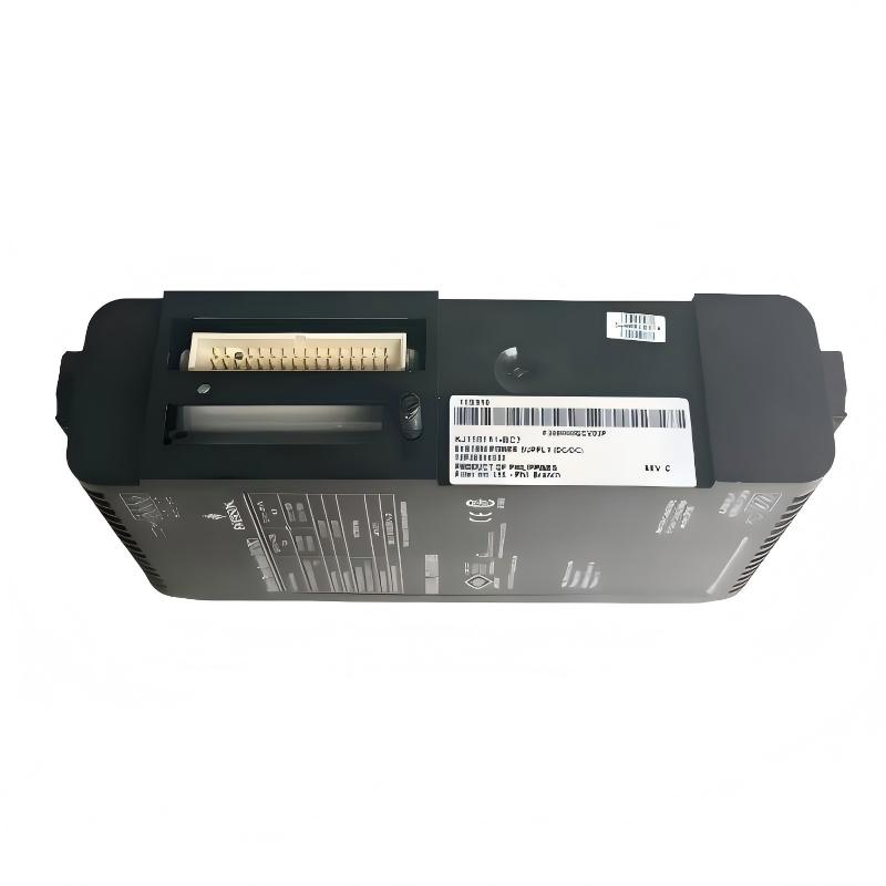
1. Introduction
The Emerson KJ1501X1-BA1 Power Supply Module is used in industrial control applications to provide DC power for electronic equipment. Stable power is essential for reliable operation of controllers, I/O modules, communication devices, and other control system components. A fault in the power supply or its associated distribution circuit can cause a range of symptoms, including equipment startup failure, intermittent resets, communication loss, abnormal module indications, and unexpected system shutdowns. However, these symptoms do not necessarily mean that the power supply itself has failed. Input voltage problems, overloaded output rails, loose connections, damaged wiring, and faults in connected equipment can produce similar behavior. This guide explains practical troubleshooting procedures for the KJ1501X1-BA1, covering power input inspection, DC output verification, load-related faults, intermittent operation, and replacement considerations.
2. Understanding the Power Supply and Its Outputs
The KJ1501X1-BA1 is identified as an Emerson industrial power supply module. Available product identification data describes the following output rails:
| Parameter | Identified Specification | Diagnostic Focus |
|---|---|---|
| Model | KJ1501X1-BA1 | Confirm the complete model number |
| Input | 120 VAC / 230 VAC, according to available identification data | Verify actual nameplate rating and supply configuration |
| +12 VDC Output | Up to 2.1 A | Check voltage stability and load current |
| +5 VDC Output | Up to 2.0 A | Check voltage stability and load current |
| +3.3 VDC Output | Up to 0.5 A | Check voltage stability and load current |
These values are identification data, not a replacement for the official electrical specification. Confirm the exact input configuration, output tolerances, combined power limit, and connector assignments for the installed revision before performing electrical tests.
3. Common Symptoms and Possible Causes
Power supply problems can appear as individual equipment faults or as wider control system disturbances.
| Observed Symptom | Possible Causes | Recommended Inspection |
|---|---|---|
| Control equipment does not start | No input power, incorrect input configuration, disconnected wiring, or failed power supply | Check the incoming circuit and approved DC test points |
| Controller repeatedly resets | Unstable DC output, excessive load, loose connections, or intermittent input power | Review voltage stability and load conditions |
| One part of the system is inactive | Problem affecting a particular output rail, branch circuit, or connected device | Trace the affected power distribution branch |
| Communication equipment loses connection | Unstable supply to communication hardware, wiring faults, or a separate network problem | Check device power and communication diagnostics |
| Power supply becomes unusually hot | Excessive load, poor ventilation, high ambient temperature, or internal fault | Inspect load and cabinet cooling conditions |
| Output voltage is outside the specified range | Input supply problem, overload, wiring resistance, or module failure | Measure at approved test points and compare with specifications |
| Fault returns after replacement | External circuit fault, incompatible replacement, or unresolved overload | Recheck system compatibility and downstream loads |
4. Safety Precautions Before Troubleshooting
The KJ1501X1-BA1 is associated with electrical power circuits. Troubleshooting should be performed by qualified personnel familiar with industrial electrical systems. Before inspection or replacement:
- Follow the plant’s lockout/tagout procedure.
- Isolate the incoming power before touching wiring or removing the module.
- Verify that the circuit is de-energized using an appropriately rated instrument.
- Allow stored energy to discharge according to the equipment instructions.
- Use suitable insulated tools and personal protective equipment.
- Apply ESD precautions when handling electronic assemblies.
- Never bypass protective devices or defeat equipment interlocks to keep a faulty supply operating.
Live measurements should only be carried out by qualified personnel using approved test points and procedures. Do not probe unknown connector pins or exposed circuit contacts.
5. Troubleshooting Procedure
5.1 Step 1: Confirm the Fault Conditions
Before disconnecting the module, collect information about the fault. Record the following:
- When the problem first appeared.
- Whether the failure is continuous or intermittent.
- Which controllers, I/O modules, or communication devices are affected.
- Whether the fault occurs during startup or during normal operation.
- Any recent maintenance, wiring changes, or system expansions.
- Relevant controller alarms and power-related diagnostic messages.
Determine whether the entire control system is affected or only one power distribution branch. A system-wide failure may indicate an upstream supply problem, while a localized failure may point toward a branch circuit or connected device.
5.2 Step 2: Inspect the Incoming Power Supply
An incorrect or unstable input supply can prevent the module from producing reliable DC outputs. Check the incoming circuit against the module nameplate and approved system wiring diagram. Verify that the supply voltage is appropriate for the actual module configuration. Inspect for:
- Tripped upstream protective devices.
- Loose or damaged input wiring.
- Incorrect line and neutral connections where applicable.
- Unstable incoming voltage.
- Damaged connectors or terminal blocks.
- Signs of overheating around input connections.
If the incoming voltage is outside the permitted range, investigate the upstream electrical distribution system before replacing the power supply module.
5.3 Step 3: Check the DC Output Rails
If the input supply is correct, qualified personnel can verify the DC outputs using approved measurement points. The identified output rails are:
- +12 VDC
- +5 VDC
- +3.3 VDC
Measure each rail using the specified test procedure and compare the results with the manufacturer’s permitted voltage tolerance. Interpret the results carefully:
- If all output rails are absent, investigate the input circuit, module installation, and possible internal power supply failure.
- If one rail is abnormal, inspect its connected load and distribution wiring before concluding that the module is defective.
- If output voltage is unstable, check for excessive load, poor connections, and fluctuations in the incoming supply.
- If the output is normal without the load but falls when equipment is connected, investigate downstream current demand and possible short circuits.
Do not disconnect loads or test unknown terminals while the system is energized. Any isolation test must follow an approved shutdown and electrical work procedure.
5.4 Step 4: Investigate Overload Conditions
An overloaded power supply may experience voltage reduction, abnormal heating, or repeated equipment resets. Review the current demand of all equipment connected to the power supply. Check both the individual output current limits and the overall permitted output power. An installation may exceed the total power rating even if each individual output rail appears to remain within its own current limit. Potential overload sources include:
- Additional control devices installed during system expansion.
- Damaged electronic equipment drawing excessive current.
- Short circuits in downstream wiring.
- Incorrectly connected field devices.
- Unexpected simultaneous startup loads.
Compare the actual load with the system design. Do not increase protective device ratings or modify output wiring to compensate for an overload.
5.5 Step 5: Inspect Connectors and Distribution Wiring
Loose or contaminated electrical connections can cause intermittent power problems. With the equipment safely isolated, inspect the relevant connectors, terminals, and wiring for:
- Loose connections.
- Corrosion or oxidation.
- Damaged insulation.
- Discolored contacts.
- Mechanical stress or damaged cable supports.
- Incorrect wiring introduced during previous maintenance.
Check the connection arrangement against the correct system drawing. Do not assume that connector positions or terminal numbers are identical across different hardware revisions.
5.6 Step 6: Check Cabinet Temperature and Ventilation
Excessive temperature can reduce power supply reliability and contribute to intermittent operation. Inspect the cabinet cooling arrangement, ventilation openings, filters, and nearby heat-producing equipment. Confirm that the operating environment remains within the module’s specified limits. If the module becomes unusually hot, do not continue operating it without investigating the cause. Check the load, cabinet temperature, airflow, and condition of surrounding equipment.
6. Diagnosing Specific Fault Conditions
6.1 The Control System Does Not Power Up
If the connected equipment remains inactive, begin with the incoming power circuit. Recommended checks:
- Confirm that the upstream power source is available.
- Check the protective devices and input wiring.
- Verify that the module is correctly installed.
- Inspect the module and connectors for physical damage.
- Measure the DC outputs at approved test points.
- Investigate the receiving equipment if the outputs are within specification.
If the input supply is correct but the module cannot produce the required outputs under the approved test conditions, the module may require replacement or specialist evaluation.
6.2 The System Resets Intermittently
Repeated controller resets can be caused by brief interruptions in DC power. Check for:
- Intermittent incoming AC supply.
- Loose input or output connections.
- Excessive load changes.
- Short circuits in downstream branches.
- Unstable output voltage during equipment startup.
Where suitable monitoring equipment is available, record the output voltage over time. A single normal voltage reading may not reveal a short-duration interruption.
6.3 One Output Rail Is Abnormal
If one DC rail is outside its specified range, identify the devices powered by that rail. Review the relevant distribution diagram and inspect the associated wiring and load. If the rail remains abnormal after external wiring and load faults have been ruled out, the power supply may have an internal fault. Do not attempt to adjust internal components or modify the output circuit unless an approved service procedure specifically allows it.
6.4 The Module Overheats
Unusual heating may indicate excessive current demand, inadequate ventilation, an abnormal input condition, or internal damage. Check the operating environment and load calculation first. If there is a burning smell, visible damage, smoke, or severe overheating, isolate the equipment immediately in accordance with site safety procedures. Do not return a visibly damaged module to service.
6.5 The Fault Persists After Replacing the Module
A replacement module does not necessarily resolve a fault caused by external equipment. If the problem remains, investigate:
- Incorrect replacement model or hardware revision.
- Input voltage or wiring configuration errors.
- Downstream short circuits.
- Excessive connected load.
- Damaged distribution connectors.
- Faults in the receiving control equipment.
Confirm that the replacement is approved for the exact system configuration before further testing.
7. Replacement and Recovery Procedure
If the KJ1501X1-BA1 is confirmed to be defective, replacement should follow the approved system maintenance procedure.
7.1 Before Removing the Original Module
Record the complete part number, hardware identification, wiring arrangement, and relevant system alarms. Confirm that the replacement module is compatible with the receiving equipment. Plan the shutdown carefully because loss of power may affect controllers, I/O devices, communication equipment, and process protection functions.
7.2 Remove and Install the Module
Isolate the power source and verify that the circuit is de-energized. Remove the original module according to the equipment instructions. Inspect the mounting position and connectors before installing the replacement. Do not transfer damaged connectors or wiring without evaluating their condition. Install the replacement carefully and confirm that it is fully seated and secured.
7.3 Restore Power and Verify Operation
After checking all connections, restore power according to the approved commissioning procedure. Verify:
- Incoming supply voltage.
- DC output voltage on each relevant rail.
- Normal startup of connected equipment.
- Controller and I/O diagnostic status.
- Communication stability.
- Absence of recurring power-related alarms.
Monitor the system under normal operating load before closing the maintenance task.
8. Preventive Maintenance Recommendations
Preventive maintenance helps identify electrical problems before they cause a production interruption. Recommended activities include:
| Inspection Item | Recommended Action | Purpose |
|---|---|---|
| Input power | Verify supply condition during scheduled maintenance | Identify upstream voltage problems |
| DC outputs | Measure at approved test points when required | Identify abnormal output voltage |
| Electrical connections | Inspect connectors and terminals under safe conditions | Prevent intermittent contact faults |
| Connected load | Review current demand after system modifications | Prevent overload |
| Cabinet ventilation | Inspect filters, airflow, and cabinet temperature | Reduce thermal stress |
| System alarms | Review power-related diagnostic history | Identify recurring problems |
Maintenance frequency should be determined by the operating environment, equipment criticality, and site maintenance policy.
9. Frequently Asked Questions
What are the common signs of a KJ1501X1-BA1 power supply fault?
Common symptoms include failure of connected equipment to start, unstable operation, repeated controller resets, abnormal DC output voltage, and power-related system alarms. These symptoms can also result from external wiring or load problems.
Why does the control system restart repeatedly?
Repeated restarts may be associated with unstable incoming power, intermittent wiring, excessive load, or a fault affecting one of the DC output rails. Check the complete power distribution path rather than assuming that the module itself has failed.
What should be checked if one DC output is abnormal?
Identify the equipment connected to the affected rail, inspect its distribution wiring, and evaluate the load. Compare measurements with the manufacturer’s specified voltage tolerance before deciding whether the module requires replacement.
Can an overloaded power supply cause communication failures?
Yes. If communication equipment receives unstable or insufficient power, it may restart or lose communication. However, network cabling, configuration, and communication hardware should also be checked.
Should the KJ1501X1-BA1 be repaired or replaced?
The decision depends on the fault, available manufacturer-approved service procedures, and the module’s condition. If the module has internal damage or cannot meet its specified output requirements, an approved replacement is generally preferable to unauthorized component-level repair.
Can a similar Emerson power supply model be used as a substitute?
Not without verification. Confirm the input voltage, output rails, current limits, mechanical arrangement, connector assignments, and system compatibility. Similar model numbers do not guarantee interchangeability.
10. Conclusion
Troubleshooting the Emerson KJ1501X1-BA1 Power Supply Module requires a systematic examination of the incoming power source, DC output rails, connected loads, electrical connections, and operating environment. The most effective diagnostic approach is to identify the scope of the failure, verify the input supply, inspect the output rails at approved test points, and investigate external load and wiring conditions before replacing the module. This method helps prevent unnecessary component replacement and reduces the risk of recurring system faults.
Technical Summary
The KJ1501X1-BA1 should be evaluated as part of the complete industrial power distribution system. Confirm the exact product ratings and wiring arrangement from the module label and applicable equipment documentation. Perform electrical tests only under approved safety procedures, and verify stable operation of the connected control equipment after corrective work.