
NewsNEWCENTER
Featured products
Contact Us
Emerson A6740 16-Channel Output Relay Module Troubleshooting and Fault Diagnosis Guide
2026-11-04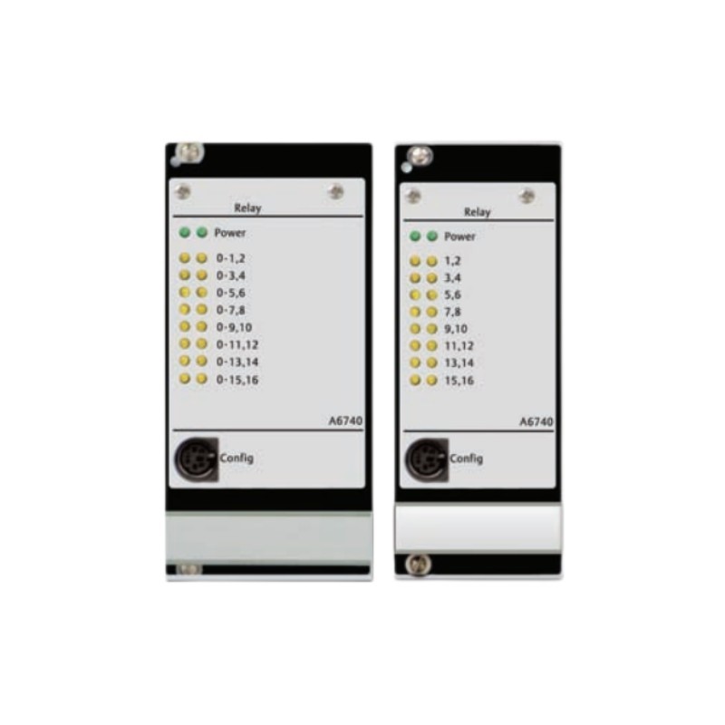
1. Introduction
The Emerson A6740 16-Channel Output Relay Module is designed for machinery monitoring and protection applications within the Emerson AMS 6500 and related CSI 6500 system configurations. It provides 16 relay outputs that can transmit selected machinery status and alarm conditions to external control, annunciation, and protection equipment. The module supports up to 60 configurable input signals, 30 logical expressions, and relay output assignments. Available input conditions include channel Clear, Alert, and Danger states. Boolean logic and configurable time delays allow the relay outputs to respond to different machinery conditions according to the application requirements. Because the A6740 may participate in critical machinery protection functions, an output fault must be investigated carefully. A relay that fails to operate does not necessarily indicate a defective module. The cause may be an incorrect logic assignment, an unavailable input signal, a wiring problem, an external circuit fault, or an internal relay problem. This guide explains practical troubleshooting methods for the Emerson A6740, including relay operation, configuration, external wiring, rack compatibility, and post-repair verification.
2. A6740 Technical Characteristics Relevant to Troubleshooting
| Parameter | Description | |—|—| | Manufacturer | Emerson | | Model | A6740 | | Product Type | 16-Channel Output Relay Module | | System Application | AMS 6500 / CSI 6500 machinery monitoring and protection systems | | Input Capacity | Up to 60 configurable inputs | | Input Conditions | Channel Clear, Alert, and Danger | | Logic Capacity | Up to 30 logical expressions | | Relay Outputs | 16 | | Logic Functions | Off, AND, OR, 2-out-of-3, and other supported combinations | | Output Delay | Configurable, 0–30 seconds | | Relay Type | Mechanical relay | | Contact Arrangement | SPDT, with selectable normally open or normally closed operation | | Contact Load | Up to 48 V, 1 A, subject to the applicable specifications | | Control Voltage | 13–32 VDC | | Maximum Power Consumption | 6 W | **Important model distinction:** The A6740 is a 12TE-wide module intended for the IMR6000 series rack. The A6740-10 is a 10TE-wide version intended for the IMR6500 series rack. These versions should not be treated as mechanically interchangeable. Confirm the exact model and rack compatibility before replacement.
3. Common A6740 Fault Symptoms
| Fault Symptom | Possible Cause | Recommended Inspection | |—|—|—| | Module does not start normally | Rack power issue, poor seating, or module hardware fault | Check rack status, power, and module installation | | Relay output does not operate | Incorrect logic assignment or missing input condition | Review logic configuration and input status | | Relay remains energized | Incorrect operating mode, active alarm condition, or wiring issue | Verify relay logic and normal-state configuration | | Relay does not release | Latching logic, persistent input condition, or relay contact problem | Check reset conditions and relay status | | DCS does not receive the output | Field wiring fault or incorrect receiving input configuration | Inspect the complete signal path | | Output changes unexpectedly | Incorrect Boolean logic or unstable input condition | Review input signals, logic expressions, and time delays | | Several relay channels fail together | Common configuration, power, or wiring problem | Investigate shared system components | | Intermittent relay operation | Loose connections, unstable control conditions, or hardware deterioration | Inspect wiring and monitor relay behavior |
4. Safety Precautions Before Troubleshooting
The A6740 may be connected to machinery alarm and shutdown circuits. Uncontrolled testing or incorrect relay operation can affect equipment protection and plant operation. Before troubleshooting: – Obtain authorization from the responsible instrumentation and control personnel. – Identify all machinery protection functions associated with the module. – Follow site lockout/tagout and electrical isolation procedures where required. – Determine whether removing or testing the module could interrupt an active protection function. – Use appropriate ESD protection when handling the module. – Verify the external circuit voltage and load before checking relay contacts. – Never short relay terminals or force an output state without an approved test procedure. – Do not change alarm logic or trip settings simply to eliminate an unwanted indication. Although the A6740 is described as a hot-swappable module, live removal must still follow the approved system and site maintenance procedures. Hot-swappable capability does not remove the need to assess protection-system risks.
5. Troubleshooting Module Power and Rack Recognition
If the A6740 does not start normally or appears unavailable in the monitoring system, begin with the rack and module installation.
5.1 Check the Module Installation
Confirm that the module is installed in the correct rack position and is fully seated. Inspect the mechanical guides and connector area for damage or contamination. For replacement work, confirm that the module width matches the rack arrangement. The A6740 and A6740-10 have different rack-width applications, so installing the wrong version can result in an unsuitable mechanical fit.
5.2 Inspect the Power Supply
The A6740 has a specified control-voltage range of 13–32 VDC and a maximum power consumption of 6 W. Verify the applicable supply arrangement using the system wiring documentation. Check for: – Abnormal rack power indications. – Loose or damaged power connections. – Unstable supply voltage. – Related rack modules reporting power problems. – Evidence of overheating or physical damage. If the supply is outside the specified range, resolve the power problem before concluding that the A6740 is defective.
5.3 Check System Recognition
If the module is not recognized, inspect the rack configuration and module identification. Confirm that the system is designed to support the installed A6740 version. If another compatible module is available, a controlled substitution test may help identify a hardware fault. Only perform this test using an approved maintenance procedure and a verified compatible replacement.
6. Troubleshooting Relay Outputs That Do Not Operate
A relay output may fail to change state because its assigned logic condition has not been satisfied. The A6740 uses configurable input signals and logical expressions to determine when individual relay outputs should operate.
6.1 Verify the Input Signal
Start by checking the input conditions assigned to the affected relay. The A6740 can use Clear, Alert, and Danger conditions from monitoring channels as logic inputs. For example, a relay may be configured to operate when a specific monitoring channel enters Danger status. If that input is not active, the relay may correctly remain in its normal state. Confirm: – The source monitoring module is operating normally. – The selected channel is correctly identified. – The required alarm condition is present. – The input signal is available to the A6740. – No configuration changes have altered the input assignment.
6.2 Review Boolean Logic
Check the logical expression associated with the affected relay. The A6740 supports Boolean logic functions such as AND and OR, as well as other supported combinations. An AND expression requires all specified conditions to be satisfied. An OR expression requires at least one specified condition. A more complex expression may depend on multiple monitoring channels. A simple example is:
Input A: Channel 1 Danger
Input B: Channel 2 Danger

Logic: AND

Relay Output:
Operates when both conditions are satisfied.
If the intended logic is OR but the configured expression is AND, the relay may not operate when only one input becomes active. Compare the configured logic with the approved cause-and-effect matrix or protection logic diagram.
6.3 Check Relay Assignment
Verify that the logical expression is assigned to the intended relay output. A correct input condition and logical expression will not produce the expected external signal if the result is assigned to the wrong relay. Review the complete configuration rather than changing individual settings without checking their relationships.
7. Troubleshooting Relay Outputs That Remain Energized
A relay that remains energized after an alarm condition clears may be affected by its configured logic, operating mode, or reset behavior. Check the following: 1. Confirm that the original alarm input has returned to its normal state. 2. Check whether the logical expression still evaluates as active. 3. Review any latching or reset behavior configured in the system. 4. Verify whether the relay is configured as normally energized or normally non-energized. 5. Check whether the external circuit is interpreting the selected contact correctly. The A6740 supports selectable relay operating arrangements. A normally open or normally closed contact selection must be understood together with the configured energized or non-energized state. Do not assume that an energized relay always represents an alarm. The actual meaning depends on the application logic and external circuit design.
8. Troubleshooting Incorrect or Delayed Relay Operation
The A6740 supports configurable time delays from 0 to 30 seconds. A relay may therefore operate after a delay rather than immediately when its input condition changes.
8.1 Check the Time Delay Setting
Review the delay assigned to the affected logical expression or output. Confirm that the configured value matches the approved protection design. A longer-than-expected delay may result from an incorrect configuration value or from misunderstanding which delay applies to the relevant logic path.
8.2 Investigate Unstable Input Signals
If the relay repeatedly changes state, inspect the originating monitoring channel. Unstable sensor signals, intermittent wiring, or changing machinery conditions may cause the input status to fluctuate. Check the trend and alarm history of the source monitoring channel. If the input itself is unstable, investigate the sensor and monitoring module before changing the relay logic.
8.3 Check the Complete Logic Path
Follow the signal from its source channel through the assigned logical expression to the selected relay. This helps identify whether the delay or unexpected behavior originates in the input condition, logic configuration, or output assignment.
9. Troubleshooting DCS and External Circuit Problems
Sometimes the A6740 relay operates correctly, but the external control system does not receive the expected signal. In this situation, the problem may be outside the relay module.
9.1 Inspect Field Wiring
Check the wiring between the A6740 output and the receiving device. Look for: – Loose terminal connections. – Incorrect conductor identification. – Damaged or broken cables. – Corrosion or contamination. – Incorrect use of normally open and normally closed contacts. – Wiring changes made during previous maintenance. Compare the actual wiring with the approved electrical drawings.
9.2 Verify Contact Ratings
The published contact load specification for the A6740 is up to 48 V and 1 A. Verify that the connected circuit remains within the applicable voltage and current limits. Do not apply higher loads based on specifications from unrelated relay modules or third-party product listings. If the receiving circuit exceeds the permitted contact rating, an appropriately engineered interface may be necessary.
9.3 Check the Receiving Device
If the relay contact changes state but the DCS or PLC input does not, inspect the receiving device’s input configuration, supply, wiring, and signal interpretation. A controlled continuity test can help verify the relay contact path when performed with the circuit safely isolated and using the correct test procedure.
10. Troubleshooting Multiple Relay Channel Failures
If several outputs fail simultaneously, investigate common causes before replacing the entire module. Possible causes include: – Rack power instability. – Incorrect module installation. – A common configuration change. – Incorrect input assignments affecting several outputs. – Shared field wiring or external circuit problems. – Internal module hardware failure. Review the system event history and maintenance records. Determine whether the problem began after a configuration download, rack maintenance activity, or field wiring modification. If all 16 outputs are affected, a module-level or common system issue becomes more likely than independent failures of every external circuit.
11. A6740 Module Replacement and Post-Repair Testing
If the diagnostic process indicates an internal module fault, replacement may be required. Before replacement, record: – Complete module model and hardware revision. – Rack type and installation position. – Existing relay channel assignments. – Boolean logic expressions. – Time delay settings. – Relay operating modes. – External wiring identification. – Current system alarm and protection status. Confirm that the replacement is the correct version. In particular, distinguish the 12TE A6740 for the IMR6000 series from the 10TE A6740-10 for the IMR6500 series. After installation, carry out the following checks: 1. Confirm that the module is correctly seated and recognized by the system. 2. Verify the power and module status indications. 3. Check the input signal assignments. 4. Review all logical expressions and relay output assignments. 5. Confirm time delay and relay operating settings. 6. Test each required output using an approved simulation procedure. 7. Verify the external DCS, PLC, or annunciator response. 8. Confirm that normal and alarm states match the approved cause-and-effect documentation. 9. Remove temporary test arrangements and authorized bypasses when testing is complete. 10. Record the results and obtain approval before returning the protection function to normal service.
12. Preventive Maintenance Recommendations
Regular maintenance helps reduce relay output faults and improves the reliability of machinery protection interfaces. – Inspect the module and rack connections during scheduled maintenance. – Maintain a current backup of A6740 configuration settings. – Keep the relay assignment schedule and cause-and-effect matrix updated. – Periodically test relay outputs according to the approved maintenance plan. – Inspect field wiring and external control circuits for damage. – Verify that connected loads remain within the specified contact ratings. – Review system event records after unexpected relay operations. – Record all module replacements and configuration changes.
13. Frequently Asked Questions
What is the main function of the Emerson A6740?
The A6740 is a 16-channel output relay module used in Emerson machinery monitoring and protection systems. It receives configured monitoring conditions, processes logical expressions, and operates selected relay outputs.
How many inputs and outputs does the A6740 support?
The module supports up to 60 configurable input signals, 30 logical expressions, and 16 relay outputs.
Why does an A6740 relay fail to operate?
Possible causes include a missing input condition, incorrect Boolean logic, an incorrect relay assignment, an unsuitable time delay, field wiring problems, or an internal relay fault.
Why does the relay remain energized after an alarm clears?
The cause may be a latching or reset configuration, a persistent input condition, or an incorrect interpretation of the relay’s energized state. Check the configured logic and external contact arrangement.
What is the difference between A6740 and A6740-10?
The A6740 is a 12TE-wide version for the IMR6000 series rack, while the A6740-10 is a 10TE-wide version for the IMR6500 series rack. Confirm the rack type before ordering or installing a replacement.
Can the A6740 be used for machinery shutdown signals?
It can provide relay outputs for configured machinery protection functions. Whether a particular output is suitable for a shutdown circuit depends on the approved system architecture, relay configuration, contact ratings, and external protection design.
Does an A6740 relay fault always mean the module needs replacement?
No. Check the input signals, logical expressions, relay assignments, time delays, field wiring, and receiving equipment first. Replace the module when testing and diagnostic evidence indicates an internal hardware fault.
14. Technical Summary
The Emerson A6740 16-Channel Output Relay Module provides configurable relay interfaces for machinery monitoring and protection systems. Its ability to process multiple input conditions through Boolean logic and time delays makes it suitable for applications involving turbine, compressor, and other critical rotating equipment. Effective troubleshooting requires a structured approach. Maintenance personnel should first verify the source input signals, then examine logical expressions, relay assignments, time delays, contact configurations, and external wiring. Rack power and module compatibility should also be checked when several outputs are affected. By maintaining accurate configuration records, testing relay channels regularly, and following approved protection-system procedures, industrial facilities can improve the reliability of their Emerson A6740 installations and reduce unnecessary module replacement.