
NewsNEWCENTER
Featured products
Contact Us
Emerson A6740 16-Channel Output Relay Module Installation and Commissioning Guide
2026-11-04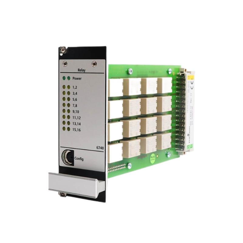
1. Product Overview
The Emerson A6740 is a 16-channel output relay module designed for use in industrial machinery monitoring and protection systems. Within an Emerson AMS 6500 Machinery Health Monitor installation, relay output modules provide an interface between monitoring functions and external control or protection circuits. The A6740 can be used to transmit relay status signals associated with machinery alarms and configured monitoring conditions. Depending on the system design, these outputs may be connected to annunciators, control system inputs, shutdown logic, or other external equipment. In a machinery protection installation, relay outputs are important because they allow monitoring information to be used by equipment outside the monitoring rack. Correct installation therefore requires attention to rack compatibility, module identification, relay configuration, field wiring, alarm logic, and commissioning tests. This guide covers the general installation and commissioning process for the Emerson A6740 16-channel output relay module. Exact terminal assignments, contact ratings, relay operating modes, and configuration procedures must be verified against the documentation for the specific module revision and installed AMS 6500 system.
2. Technical Specifications
| Parameter | Description |
|---|---|
| Manufacturer | Emerson |
| Model | A6740 |
| Product Type | 16-channel output relay module |
| Primary Function | Provides relay output interfaces for monitoring and protection system signals |
| Output Channels | 16 relay output channels |
| System Application | Industrial machinery monitoring and protection |
| Typical Platform Context | Emerson AMS 6500 Machinery Health Monitor installations; confirm exact rack and system compatibility |
| External Interface | Relay contacts connected to approved field circuits |
| Configuration | Depends on the installed system, assigned relay functions, and application logic |
The table describes the module’s general role. It does not establish electrical contact ratings, terminal numbering, coil characteristics, isolation ratings, or supported wiring arrangements. These values must be obtained from the applicable A6740 technical documentation before field wiring is performed.
3. Understanding the Role of the A6740 in a Machinery Protection System
A machinery monitoring system collects measurements from sensors, evaluates operating conditions, and generates status or alarm information. Relay output modules provide a physical switching interface so that selected conditions can be communicated to external equipment. A typical system arrangement can be represented as follows:
Machinery and Rotating Equipment
              |
              v
Vibration / Displacement Sensors
              |
              v
Monitoring and Protection Modules
              |
              v
Alarm and Relay Logic
              |
              v
Emerson A6740 Relay Output Module
              |
              v
External Control or Protection Circuits
The A6740 does not replace the measurement functions of vibration or temperature monitoring modules. Its role is to provide relay outputs based on the functions and logic assigned within the monitoring system. Possible applications include:
- Transmitting selected machinery alarm states to a control room.
- Providing relay status signals to a distributed control system (DCS).
- Interfacing monitoring alarms with external annunciation equipment.
- Supporting approved machinery protection and shutdown logic.
- Providing separate output signals for multiple monitoring conditions.
The actual function of each relay must be defined by the system configuration and approved protection design. Do not assume that every channel is assigned to a particular alarm or trip function by default.
4. Pre-Installation Preparation
Before installing the A6740, confirm that the module is suitable for the target rack and application. A relay output module must match the system’s hardware arrangement and electrical requirements.
4.1 Verify the Module Model
Check the product label and confirm that the module is identified as A6740. Record the complete part number, hardware revision, serial number, and any other identification information available on the nameplate. If the module is being used as a replacement, compare its identification with the existing unit and confirm that the replacement is approved for the installed system. Similar module names do not necessarily indicate identical hardware or functionality.
4.2 Confirm Rack and System Compatibility
Verify the supported rack type, module position, connector arrangement, and system configuration. Confirm that the installed AMS 6500 system recognizes the A6740 and that the required monitoring or controller modules are present. Do not rely solely on physical fit. A module that can be inserted into a rack is not automatically compatible with every rack configuration or system revision.
4.3 Inspect the Module
Before installation, inspect the module for:
- Cracked or damaged housing.
- Bent, contaminated, or damaged connectors.
- Signs of corrosion or moisture exposure.
- Burn marks or evidence of overheating.
- Loose mechanical components.
- Damaged identification labels.
Do not install a module with visible damage until it has been assessed by qualified personnel.
4.4 Prepare Tools and Documentation
Prepare the approved installation documentation, rack layout, relay assignment schedule, wiring drawings, and commissioning checklist. Use appropriate insulated tools and electrostatic discharge protection. The field wiring plan should identify the external circuit connected to each relay channel, including its signal purpose, normal operating state, and required response to an alarm or fault.
5. Installation Safety Requirements
Relay outputs may be connected to external control or protection circuits. Incorrect wiring or unintended relay operation can cause equipment trips, alarms, or loss of protection functions. Before installation:
- Obtain authorization from the responsible control and instrumentation personnel.
- Assess the impact of removing or installing the module on active machinery protection functions.
- Apply the site’s lockout/tagout and electrical isolation procedures where required.
- Verify that external field circuits are in a safe condition before handling conductors.
- Use ESD protection when handling the module.
- Do not assume that relay contacts are voltage-free under every installation condition; verify the external circuit design.
- Do not perform live wiring changes unless an approved procedure explicitly permits them.
If the A6740 is part of a shutdown or trip system, establish an approved temporary protection arrangement before carrying out work that could interrupt its function.
6. A6740 Module Installation Procedure
6.1 Confirm the Installation Position
Check the rack layout and identify the designated position for the A6740. Confirm that the selected slot is approved for the relay output module and that the required rack connections are available. Record the slot number and the module’s intended role in the system documentation.
6.2 Prepare the Rack
Follow the approved rack maintenance procedure before inserting or removing the module. Confirm the required power and protection-system conditions. If the installation involves replacing an existing relay module, document its wiring and configuration before removal. Label field conductors clearly so that they can be returned to the correct terminals or interface points.
6.3 Insert the Module
Align the A6740 with the correct rack guides and connector position. Insert it carefully and evenly, following the manufacturer’s installation instructions. Do not force the module into the rack. Resistance during insertion may indicate incorrect alignment, an obstruction, or connector damage. Once inserted, secure the module using the specified mechanical retaining arrangement. Confirm that it is fully seated and mechanically stable.
6.4 Verify Mechanical Installation
Check that the module is correctly positioned and that its connectors are properly engaged. Confirm that no cables, adjacent modules, or rack components interfere with installation.
7. Field Wiring and Relay Channel Connections
The A6740 provides 16 relay output channels. Correct field wiring is essential because each channel may operate an independent external circuit.
7.1 Prepare the Relay Wiring Schedule
Create a channel-by-channel wiring schedule before connecting field conductors.
| Information | Required Record |
|---|---|
| Channel Identification | Relay channel number as defined by the approved documentation |
| Assigned Function | Alarm, status, trip interface, or other approved function |
| External Destination | DCS input, annunciator, control circuit, or protection interface |
| Contact Arrangement | Verify the applicable contact configuration from the module documentation |
| Normal State | Document the intended relay state during normal operation |
| Alarm State | Document the expected relay response to the assigned condition |
| Field Cable Identification | Record cable and conductor identifiers |
7.2 Verify Contact Ratings
Before connecting external circuits, confirm the permitted relay contact voltage, current, load type, and switching limits for the installed A6740 revision. Do not connect a load based on assumptions or on the ratings of another Emerson relay module. If an external load exceeds the specified limits, an appropriately engineered interface arrangement may be required.
7.3 Connect Field Conductors
Use the approved wiring diagram to identify the correct connection points. Confirm conductor identification and polarity where relevant to the external circuit. Keep signal wiring organized and separated from power wiring in accordance with the site’s electrical installation standards. Use suitable cable protection and strain relief.
7.4 Check Wiring Continuity
After wiring, perform continuity and insulation checks using methods appropriate for the connected circuits. Disconnect sensitive electronic equipment where required by the test procedure. Do not apply insulation-test voltages to connected module electronics or relay circuits unless the manufacturer explicitly permits the procedure.
8. Relay Configuration and Channel Assignment
The A6740’s 16 output channels must be assigned according to the intended monitoring and protection functions. The configuration should be consistent with the approved control narrative, alarm schedule, and machinery protection design. Typical configuration activities include:
- Assigning each relay channel to the intended monitoring or alarm condition.
- Defining the required normal and alarm states.
- Verifying relay logic and any applicable latching behavior.
- Confirming reset behavior and external acknowledgement requirements.
- Checking the relationship between monitor alarms and relay outputs.
- Verifying any required fail-safe response as specified by the system design.
Do not assume that the A6740 automatically provides a particular fail-safe state or relay sequence. These behaviors depend on the hardware design, configuration, and external wiring arrangement.
9. Commissioning and Functional Testing
Commissioning confirms that the A6740 is installed correctly and that its relay outputs operate as intended.
9.1 Initial System Inspection
Before functional testing, confirm:
- The module is installed in the approved rack position.
- The rack and monitoring system show no unresolved installation faults.
- All field conductors are correctly identified and secured.
- The channel assignment schedule matches the configured system.
- External circuits are ready for controlled testing.
9.2 Verify Individual Relay Channels
Test each relay channel using the approved system test method. Confirm that the expected external input or indicator changes state when the corresponding test condition is applied. Use a controlled test signal or approved simulation method. Avoid generating a real machinery trip merely to test a relay output.
9.3 Verify Normal and Alarm States
For each assigned channel, check the documented normal state and the expected state during the relevant alarm condition. Confirm that the receiving equipment interprets the contact state correctly.
9.4 Verify External System Response
Where the A6740 is connected to a DCS, PLC, annunciator, or protection interface, verify the complete signal path. Confirm that the external system receives the correct channel indication and displays or processes it as intended.
9.5 Document Test Results
Record the test date, module identification, channel number, assigned function, test method, expected response, actual response, and any corrective action. Do not return the system to normal operation until all required tests have been completed and approved.
10. Common Installation Problems
| Problem | Possible Cause | Corrective Action |
|---|---|---|
| Module not recognized | Incorrect slot, poor seating, rack issue, or incompatible hardware revision | Verify rack compatibility, installation position, and connector condition |
| Relay does not change state | Incorrect channel assignment, missing control condition, wiring fault, or relay fault | Check configuration, field wiring, and approved channel test procedure |
| External DCS input remains unchanged | Incorrect field wiring, receiving input configuration, or contact-state interpretation | Check the complete signal path and verify the external input logic |
| Unexpected relay operation | Incorrect logic assignment, alarm configuration, or wiring identification | Review the channel schedule and approved control narrative |
| Intermittent output | Loose wiring, poor connection, unsuitable load, or external circuit instability | Inspect connections and verify load conditions against specified ratings |
| Multiple channels affected | Common rack, configuration, or external wiring issue | Investigate shared system components before replacing the module |
11. Preventive Maintenance Recommendations
Regular maintenance helps preserve relay output reliability and reduces the likelihood of unexpected alarm-interface problems.
- Inspect module seating and connector condition during scheduled maintenance.
- Check field wiring for loose terminals, corrosion, and mechanical damage.
- Maintain an up-to-date 16-channel relay assignment schedule.
- Verify external load conditions against the specified contact ratings.
- Perform periodic functional tests according to the site’s maintenance plan.
- Keep a record of module revisions, replacement history, and configuration changes.
- Review alarm and trip interface logic after any system modification.
12. Frequently Asked Questions
What is the Emerson A6740 used for?
The Emerson A6740 is a 16-channel output relay module used to provide relay-based interfaces between machinery monitoring or protection functions and external control, alarm, or protection circuits.
How many output channels does the A6740 provide?
The A6740 is identified as a 16-channel output relay module. The function assigned to each channel depends on the system configuration and application design.
Can the A6740 connect directly to a DCS?
It may be used as part of a relay interface to a DCS when the external circuit, contact ratings, wiring arrangement, and system configuration are compatible. Verify the complete interface design before connection.
Are all 16 relay channels configured in the same way?
Not necessarily. Channel assignments and operating logic depend on the machinery monitoring application. Each channel should be documented and tested individually.
What should be checked if a relay output does not operate?
Check the assigned monitoring condition, relay configuration, module installation, field wiring, external load, and receiving equipment. Use the approved test procedure to isolate the fault.
Can the A6740 be replaced while the rack is powered?
Do not assume that live replacement is permitted. Follow the exact module and rack maintenance instructions and the site’s machinery protection procedures before removing or inserting the module.
13. Technical Summary
The Emerson A6740 16-channel output relay module provides relay interfaces for industrial machinery monitoring and protection applications. Its installation requires correct rack compatibility, careful module handling, accurate channel identification, properly engineered field wiring, and configuration consistent with the approved protection design. A complete commissioning process should verify every assigned relay channel, confirm the expected normal and alarm states, and test the signal path to connected external equipment. Maintaining accurate wiring schedules and carrying out periodic functional checks can help support dependable operation in Emerson AMS 6500 installations.