Introduction
Reliable condition monitoring is essential for industrial facilities that depend on continuously operating rotating machinery.
Steam turbines, gas turbines, compressors, generators, pumps and large motors can operate under substantial mechanical and thermal loads. A developing mechanical problem may initially produce only a small change in vibration, shaft position or machine operating behavior. If that change is not detected in time, the condition can progress into equipment damage or an unexpected shutdown.
Bently Nevada machinery monitoring technologies are designed to provide engineers with continuous information about the condition and behavior of critical rotating equipment.

A complete monitoring installation can include:
- Proximity probes
- Proximity sensor systems
- Extension cables
- Signal processing modules
- Machinery monitoring modules
- Speed sensors
- Keyphasor-related measurement
- Vibration monitoring channels
- Alarm and protection functions
- Engineering and diagnostic software
Correct installation is extremely important because the quality of the final monitoring result depends not only on the monitoring module itself, but also on sensor positioning, cable routing, grounding, configuration and commissioning.
This guide explains the major considerations when installing and integrating a Bently Nevada machinery protection and vibration monitoring system.
1. Understanding the Purpose of a Machinery Monitoring System
Before installation begins, engineers should clearly define what the monitoring system needs to accomplish.
A machinery protection system may be responsible for detecting abnormal conditions such as:
- Excessive shaft vibration
- Excessive axial movement
- Abnormal shaft position
- Overspeed conditions
- Bearing-related abnormalities
- Rotor instability
- Other machine-specific conditions
The monitoring system can then provide alarms or protective actions according to the application design.
Condition monitoring and machinery protection should be considered together, but they are not exactly the same function.
Protection focuses on responding to potentially dangerous conditions.
Condition monitoring focuses on understanding machine behavior over time.
2. Typical Bently Nevada Monitoring Architecture
A typical rotating-machine monitoring arrangement can be represented as:
Machine → Sensor → Proximity System → Monitoring Module → Control/Protection System → Operator Interface
Each layer has a specific purpose.
Machine
The turbine, compressor, motor, generator or other rotating asset produces mechanical behavior that needs to be observed.
Sensor
The sensor detects a physical parameter.
Signal Conditioning
The sensor signal is converted into a usable electrical signal.
Monitoring Module
The monitoring system processes the signal and determines whether the measured condition is within the configured operating range.
Control or Protection System
The resulting information can be transferred to a larger plant control architecture.
Operator Interface
Operators and maintenance engineers can view machine status, alarms and trends.
3. Sensor Selection
Sensor selection should be performed according to the machine and measurement objective.
Different measurements may require different sensor technologies.
For example, proximity measurement can be used for shaft displacement and relative shaft vibration.
Other applications may require:
- Velocity measurement
- Acceleration measurement
- Speed measurement
- Temperature measurement
The sensor should therefore be selected based on the parameter that needs to be measured rather than simply choosing a sensor because it is physically compatible with the monitoring rack.
4. Proximity Probe Installation
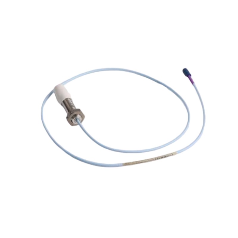
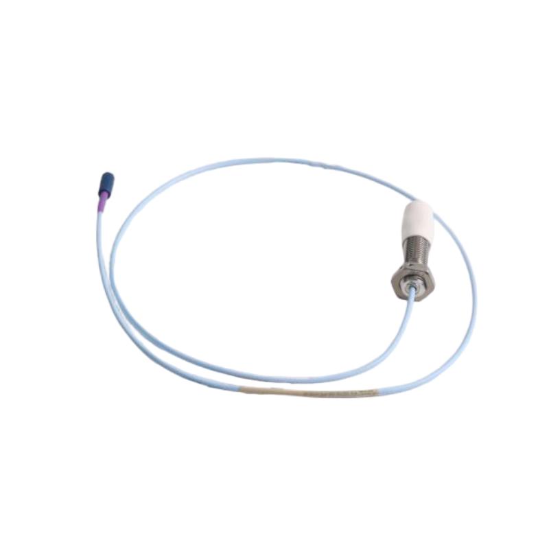
Proximity probes are commonly used for non-contact measurement of rotating shafts.
The probe generates an electromagnetic field and detects changes caused by the proximity of the conductive shaft surface.
Correct installation requires careful attention to:
- Probe location
- Probe orientation
- Target surface condition
- Probe gap
- Cable length
- Mechanical mounting
The probe should be installed in a mechanically stable position.
5. Probe Gap Adjustment
Probe gap is one of the most important installation parameters.
If the probe is positioned too close to the shaft, there may be insufficient measurement range.
If it is positioned too far away, the signal may not operate within the expected range.
The correct gap depends on the specific sensor system and monitoring application.
Engineers should therefore use the appropriate technical specification and commissioning procedure for the actual probe system.
6. Shaft Surface Considerations
The shaft surface can affect measurement quality.
Engineers should inspect the measurement location for:
- Surface damage
- Excessive corrosion
- Irregular geometry
- Unwanted runout
- Contamination
A suitable measurement target is important for obtaining stable readings.
If the shaft surface is unsuitable, the monitoring signal may contain abnormal variations that do not represent actual machine vibration.
7. Probe Orientation
The direction of the measurement should correspond to the mechanical behavior being monitored.
For radial shaft vibration, probes are often installed in appropriate radial directions.
For axial position, the probe arrangement is different.
The installation should therefore be based on the machine drawing and monitoring design.
Incorrect orientation can result in measurements that do not represent the intended mechanical parameter.
8. Extension Cable Installation
The cable between the probe and signal-conditioning equipment is an important part of the measurement system.
During installation, cables should be protected against:
- Excessive heat
- Mechanical damage
- Vibration
- Oil contamination
- Sharp edges
- Electromagnetic interference
Cable routing should also be planned to prevent unnecessary exposure to high-power electrical conductors.
9. Cable Separation
Signal cables should be routed appropriately in relation to high-current power cables.
Power conductors can generate electromagnetic interference.
If sensitive measurement cables are routed incorrectly, unwanted electrical noise can enter the monitoring signal.
Good installation practice should therefore maintain appropriate separation between:
- Sensor cables
- Motor power cables
- Generator cables
- Variable frequency drive output cables
- High-current conductors
10. Grounding and Shielding
Grounding is an important part of instrumentation installation.
Improper grounding can introduce:
- Noise
- Ground loops
- Signal instability
- Communication problems
The grounding and shielding method should follow the equipment design and plant electrical standards.
Engineers should avoid making ad-hoc grounding connections simply because a signal appears noisy.
The correct approach is to identify the source of interference and verify the complete grounding architecture.
11. Monitoring Module Installation
Monitoring modules should be installed in the appropriate rack or system architecture.
Before inserting a module, engineers should verify:
- Correct module type
- Rack compatibility
- Power availability
- Slot assignment
- Configuration requirements
- Wiring arrangement
Installing an incorrect module can result in configuration errors or unexpected behavior.
12. Power Supply Verification
The monitoring system requires a stable power source.
Before commissioning, verify:
- Supply voltage
- Polarity where applicable
- Grounding
- Fuse or circuit protection
- Power distribution
- Redundant supply arrangements if applicable
Power problems can sometimes appear to be sensor or communication faults.
Therefore, power should always be checked during initial troubleshooting.
13. I/O Wiring Verification
Every monitoring channel should be verified against the engineering documentation.
For each channel, engineers should confirm:
- Sensor identity
- Channel number
- Signal type
- Terminal assignment
- Cable identification
- Alarm function
- Trip function where applicable
A wiring error can cause a perfectly functioning sensor to appear faulty.
14. Channel Configuration
After the physical installation is complete, monitoring channels must be configured.
Configuration parameters may include:
- Measurement type
- Engineering units
- Scale
- Alarm limits
- Danger limits
- Signal filtering
- Speed-related parameters
- Machine identification
The exact configuration depends on the monitoring application.
15. Alarm and Trip Settings
Alarm settings should never be selected arbitrarily.
The correct thresholds depend on:
- Machine design
- Manufacturer requirements
- Operating speed
- Bearing configuration
- Normal vibration levels
- Process conditions
- Protection philosophy
A monitoring system is only as useful as its alarm strategy.
If the thresholds are too low, operators may receive excessive nuisance alarms.
If they are too high, a developing problem may not be recognized quickly enough.
16. Startup Commissioning
Commissioning should normally proceed in stages.
A practical sequence is:
Step 1: Visual Inspection
Check:
- Wiring
- Cable routing
- Module installation
- Mechanical mounting
Step 2: Power Verification
Confirm stable system power.
Step 3: Channel Verification
Check each measurement channel.
Step 4: Sensor Verification
Confirm sensor output and expected measurement behavior.
Step 5: Configuration Verification
Confirm channel parameters.
Step 6: Alarm Testing
Verify alarm functions.
Step 7: System Integration
Confirm communication with the plant control system.
17. Static Testing Before Machine Startup
Whenever practical, measurement channels should be tested before rotating equipment is started.
This can help identify wiring and configuration errors before the machine reaches operating speed.
Typical checks include:
- Sensor continuity
- Channel identification
- Signal response
- Alarm logic
- Communication
- Display values
Finding an installation error before startup is significantly easier than diagnosing the same problem while the machine is operating.
18. Initial Machine Startup
During initial startup, engineers should carefully observe the monitoring system.
Important parameters may include:
- Shaft vibration
- Shaft position
- Speed
- Bearing measurements
- Alarm status
The first operating data should be recorded as part of the machine commissioning documentation.
This provides a baseline for future comparison.
19. Establishing a Baseline
A baseline is extremely valuable for condition monitoring.
A baseline represents normal machine behavior under defined operating conditions.
Future measurements can be compared with this baseline.
For example:
Initial Condition → Normal Trend → Gradual Change → Abnormal Trend
This makes trend analysis more meaningful than relying on a single measurement.
20. Vibration Trend Monitoring
After commissioning, the system should be monitored continuously.
Engineers can examine:
- Overall vibration
- Changes over time
- Operating-speed effects
- Start-up behavior
- Shutdown behavior
- Load-related changes
A gradual increase can sometimes be more significant than a single high measurement that quickly returns to normal.
21. Troubleshooting Abnormal Measurements
If an unexpected vibration signal appears, engineers should not immediately assume that the machine has a mechanical fault.
The problem may originate from:
- Sensor installation
- Cable damage
- Electrical interference
- Incorrect configuration
- Grounding
- Signal conditioning
- Actual mechanical vibration
A systematic troubleshooting sequence is therefore important.
22. Recommended Troubleshooting Sequence
A practical approach is:
Check the Alarm → Check the Channel → Check the Sensor → Check the Cable → Check the Configuration → Check the Machine
This prevents unnecessary replacement of expensive monitoring hardware.
If multiple channels show abnormal behavior simultaneously, engineers should also investigate common causes such as power supply, grounding or system-level problems.
23. Communication With the Plant Control System
Machinery monitoring information may be integrated with:
- PLC systems
- DCS systems
- SCADA
- HMI systems
- Plant historians
The integration architecture depends on the specific installation.
The objective is to make important machine-health information available to operators and maintenance personnel.
24. Integration With Turbine Control
For turbine applications, machinery protection information can be particularly important.
A turbine control architecture may combine:
- Speed measurement
- Vibration monitoring
- Shaft position
- Process measurements
- Valve control
- Protection functions
The monitoring system therefore becomes part of a larger control and protection strategy.
25. Integration With Compressor Systems
Compressors often require continuous monitoring because rotating components operate under demanding conditions.
Monitoring may help identify:
- Rotor vibration
- Bearing problems
- Mechanical instability
- Operating-condition changes
The monitoring information can then support both protection and maintenance decisions.
26. Maintenance of Monitoring Hardware
The monitoring system itself requires maintenance.
Maintenance personnel should periodically inspect:
- Sensor mounting
- Cable condition
- Connectors
- Rack condition
- Power supplies
- Communication status
Maintenance should also include review of historical alarms and trends.
27. Sensor Replacement
Sensors are exposed to industrial environments and may eventually require replacement.
When replacing a sensor, engineers should verify:
- Correct model or compatible sensor type.
- Correct cable arrangement.
- Mechanical mounting.
- Probe gap.
- Channel configuration.
- Signal response.
- Alarm behavior.
A sensor replacement should be followed by functional verification.
28. Importance of Spare Parts
Critical machinery monitoring systems should have an appropriate spare-parts strategy.
Potential spare items may include:
- Proximity probes
- Extension cables
- Signal-conditioning components
- Monitoring modules
- Power supplies
- Communication components
The required inventory depends on equipment criticality and plant maintenance strategy.
29. Documentation Requirements
A professional installation should include accurate documentation.
Recommended records include:
- Sensor location drawings
- Channel assignments
- Wiring diagrams
- Configuration files
- Alarm settings
- Commissioning results
- Baseline measurements
- Maintenance records
Good documentation can significantly reduce troubleshooting time in the future.
30. Common Installation Mistakes
Several mistakes can reduce monitoring reliability.
Incorrect Probe Gap
Can cause inaccurate or unstable measurements.
Poor Cable Routing
Can increase electrical interference.
Incorrect Channel Assignment
Can result in misleading machine information.
Improper Grounding
Can create noise and signal instability.
Incorrect Alarm Limits
Can result in nuisance alarms or insufficient protection.
Inadequate Documentation
Can make future maintenance unnecessarily difficult.
31. Condition Monitoring and Predictive Maintenance
Once a reliable monitoring system is installed, the collected information can support predictive maintenance.
Instead of waiting for a machine to fail, maintenance teams can monitor condition changes.
For example:
Stable Vibration → Increasing Vibration → Diagnostic Investigation → Planned Maintenance
This allows maintenance to be better coordinated with production schedules.
32. Why Installation Quality Matters
A sophisticated monitoring module cannot compensate for poor field installation.
The final measurement quality depends on the complete signal chain:
Mechanical Target → Probe → Cable → Signal Conditioning → Monitoring Module → Configuration → Control System
Every part of this chain matters.
A problem anywhere in the chain can affect the final result.
33. Recommended Commissioning Checklist
Before placing a Bently Nevada machinery monitoring system into normal service, engineers should verify:
34. Long-Term Monitoring Strategy
Commissioning is only the beginning of a machinery-monitoring program.
Long-term reliability requires regular review of:
- Vibration trends
- Alarm events
- Machine operating conditions
- Sensor health
- Monitoring-system status
Maintenance teams should compare current behavior with historical operating data.
This makes it easier to recognize gradual degradation.
Conclusion
Bently Nevada machinery protection and vibration monitoring systems can provide critical information about the condition of rotating industrial equipment.
However, successful monitoring depends on much more than installing a monitoring module.
Correct sensor selection, probe positioning, cable installation, grounding, channel configuration, alarm settings and commissioning procedures are all important.
Once the system is properly commissioned, baseline data can be established and used for long-term trend analysis.
For turbines, compressors, generators, pumps and other critical rotating assets, this approach can help plants move from reactive maintenance toward condition-based and predictive maintenance.
The most effective monitoring strategy combines accurate measurement, reliable protection, systematic diagnostics, good documentation and experienced engineering judgment.