

ProductPRODUCT
Featured products
Contact Us
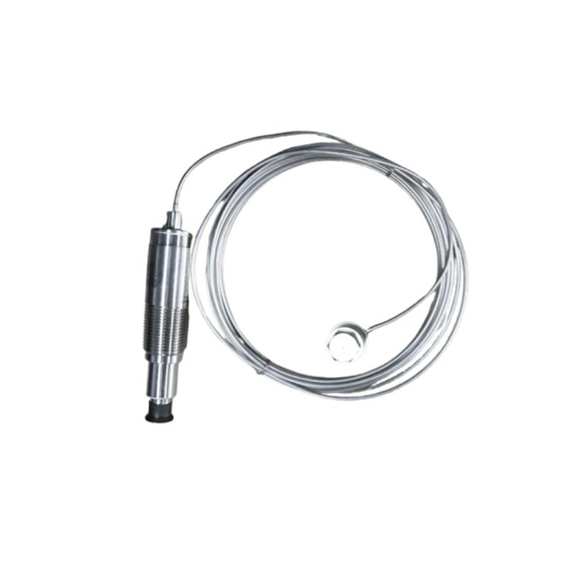
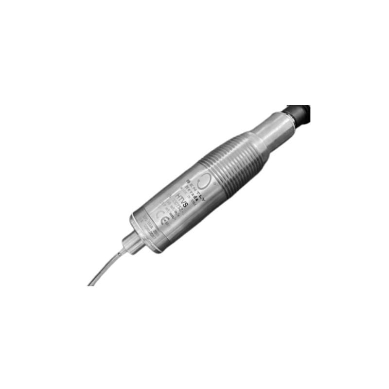
- Bently Nevada
- 330752-25-05
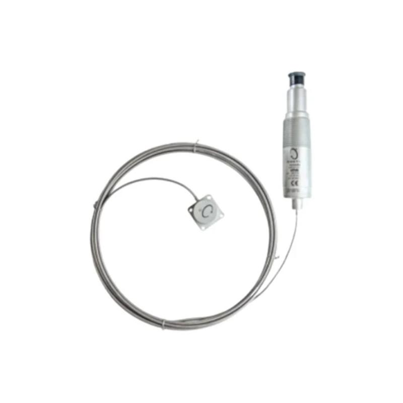
- High Temperature Velomitor System
- USA
- 33.4 mm × 152.1 mm
- 0.71kg
- Xiamen, China
- New & In Stock
- T/T, PayPal, Western Union
- 1 Year
- 1-3 Working Days
- DHL, UPS, TNT, FedEx and EMS.
- 24-Hour Service
- COO
- 3
Our advantage

Global Logistics
We have a 10-year logistics and express cooperation agreement, so our products can be shipped to any place in the world.

Brand new and original
Our products are imported in bulk from the place of origin. Because of the cooperative relationship, our products are all original and 100% new.

24-hour service
We provide 7*24 hours service to our customers. We will be there whenever you need us.

Price advantage
All our products are priced very favorably because we have our own warehouse and supply.
| Company Information | |||
| [email protected] | |||
| Mobile | +8615980777398 | ||
| +8615980777398 | |||
| 15980777398 |
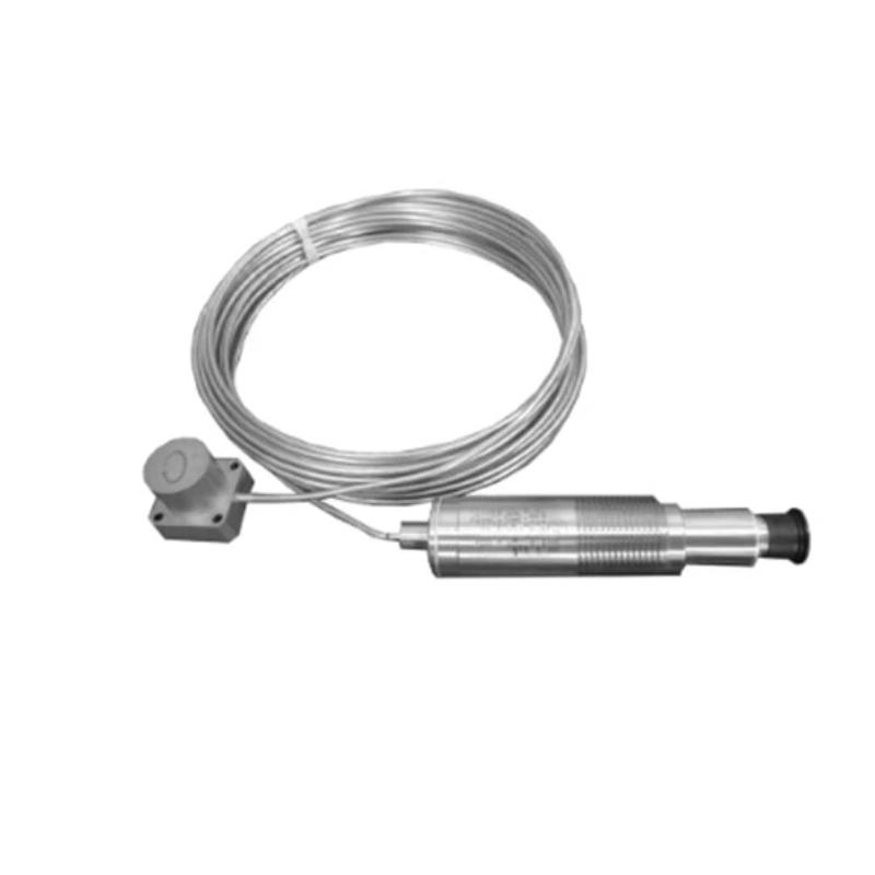
Bently Nevada 330752-25-05 High-Temperature Vibration Sensor — Product Description and Technical Data
1. Product Overview
The Bently Nevada 330752-25-05 is a model in the high-temperature Velomitor vibration-sensor family. It is intended for industrial machinery monitoring where vibration must be measured at a location exposed to elevated temperatures.
Vibration monitoring is an important part of machinery maintenance in power generation, petrochemical processing, metal production, and other heavy industries. Changes in vibration can provide useful information about equipment condition, especially when measurements are recorded consistently and compared with a reliable operating baseline.
A high-temperature sensor is particularly useful when the machine’s mounting surface is too hot for a conventional sensor with integrated electronics. The sensing head can be located near the measurement point while the associated electronics are installed in a cooler area, subject to the model’s specified temperature limits and installation requirements.
Important model-identification note: The exact specifications of the 330752-25-05 configuration should be confirmed against its product label and model-specific technical drawing. The suffixes and cable options matter, and specifications from the related 330750 family should not automatically be treated as confirmed specifications for every 330752 variant. The details below distinguish general application information from values that require model-specific confirmation.
2. Brand and Series Information
| Item | Description |
|---|---|
| Brand | Bently Nevada |
| Model | 330752-25-05 |
| Product family | High-temperature Velomitor vibration-sensor family |
| Product category | Industrial vibration-monitoring sensor |
| Primary measurement | Vibration velocity, subject to the exact model configuration |
| Intended environment | Industrial machinery installations with elevated mounting-surface temperatures |
| Cable configuration | The 25 configuration appears to indicate a nominal cable-length option; confirm the exact length from the unit label or ordering specification |
| Approval configuration | The -05 suffix must be verified against the exact model documentation and certification markings |
| Typical system role | Field sensor connected to a compatible machinery-monitoring channel |
| Main selection considerations | Temperature, sensitivity, frequency response, mounting, cable length, electrical interface, and area classification |
The model should be selected as part of a complete measurement system. The sensor, cable, signal-conditioning electronics, monitoring channel, mounting hardware, and installation environment all affect the quality and reliability of the final measurement.
3. Detailed Technical Specifications
The 330752-25-05 is associated with the 330750/330752 High Temperature Velomitor System. The principal performance figures below describe this sensor family; confirm the exact ordering-code requirements before using them for engineering acceptance or replacement.
| Parameter | Technical specification |
|---|---|
| Model | 330752-25-05 |
| Brand | Bently Nevada |
| Product series | 330750 / 330752 High Temperature Velomitor System |
| Sensor type | Piezoelectric vibration velocity transducer |
| Measurement quantity | Vibration velocity |
| Nominal sensitivity | 5.7 mV/mm/s (145 mV/in/s), ±5% |
| Frequency response | 15–2,000 Hz, ±3 dB |
| Higher-accuracy frequency range | 20–1,000 Hz, ±0.9 dB |
| Amplitude linearity | Approximately ±2% up to 152 mm/s peak |
| Amplitude range | 635 mm/s peak below 680 Hz; 2,940 m/s² peak above 680 Hz |
| Mounted resonant frequency | Greater than 5 kHz |
| Transient temperature sensitivity | Approximately 0.0762 mm/s/°C |
| Output bias voltage | −12 ±2 VDC |
| Broadband noise | Approximately 0.127 mm/s RMS, nominal |
| Sensing-head operating temperature | −55°C to +400°C |
| Integral hardline cable operating temperature | −55°C to +400°C |
| Electronics operating temperature | −55°C to +121°C |
| Shock survivability | Approximately 2,500 g peak |
| Relative humidity | Up to 100%, non-submerged, under specified conditions |
| Case construction | 300-series stainless steel |
| Case isolation | Isolated case design |
| Connector | Hermetically sealed, 2-pin MIL-C-5015 receptacle |
| Cable type | Integral hardline cable |
| Nominal cable length | Approximately 2.5 m for the 25 cable option; verify the exact ordered configuration |
| Cable diameter | Approximately 3.2 mm |
| Sensor-head diameter | Approximately 25.4 mm |
| Sensor-head mounting thread | M8 × 1, as shown in the applicable 330752 dimensional drawing |
| Electronics housing diameter | Approximately 33.4 mm |
| Electronics housing length | Approximately 152.1 mm |
| Additional mounting dimensions | Drawing includes 46.6 mm and 68.6 mm dimensions, plus connector and mounting-interface details |
| Overall assembly dimensions | Dependent on the sensing-head configuration, cable routing, and electronics arrangement |
| Typical unit weight | Approximately 0.715 kg; confirm against the supplied unit and packing specification |
| Approval suffix | -05; verify the exact certification markings and approval documentation for the supplied unit |
Dimensional information
The system has three principal sections: the sensing head, the integral cable, and the electronics assembly. The sensing head is designed to mount near the machine surface being monitored, while the electronics can be installed in a cooler area.
The sensing head is approximately 25.4 mm in diameter. The drawing also identifies an M8 × 1 mounting thread and other mounting-related dimensions. The electronics housing is approximately 33.4 mm in diameter and 152.1 mm long, with a hermetically sealed two-pin connector.
These measurements should not be treated as one overall length. The cable is flexible in routing but must comply with its minimum bend radius and temperature limits. For a final mechanical fit check, use the drawing for the exact 330752 configuration.
Weight information
A typical unit weight of approximately 0.715 kg is a useful preliminary planning figure for the 330752-25-05. Actual delivered weight may vary with the exact configuration and accessories, and packaged shipping weight is not the same as the bare assembly weight.
For procurement records, maintenance documentation, or engineering calculations, the weight on the manufacturer’s model-specific documentation should take precedence over a general catalogue estimate.
4. Product Introduction and Operating Principle
The 330752-25-05 belongs to a high-temperature vibration velocity sensor family designed to address a practical limitation of conventional vibration sensors: their electronics may not tolerate the temperature of the machine surface where vibration needs to be measured.
In the 330750/330752 design, the sensing element is separated from the signal-conditioning electronics. The sensing head and integral hardline cable can operate at temperatures up to 400°C, while the electronics must remain within their lower operating-temperature limit of 121°C.
The sensor converts mechanical vibration into an electrical signal representing vibration velocity. The signal can then be used by a compatible monitoring system to trend machine vibration and support condition assessment.
This arrangement is especially useful where vibration measurements must be collected close to hot machinery components without placing the electronics directly in the same thermal environment.
The sensor is not a standalone machine-diagnostic instrument. It provides a measurement signal that must be interpreted by a compatible monitoring system and evaluated alongside operating speed, load, machine configuration, historical trends, and other relevant information.
5. Main Applications
5.1 Turbines and power-generation equipment
Turbines and associated machinery can have mounting locations exposed to high temperatures. A high-temperature velocity sensor may be suitable for monitoring vibration at selected casings, support structures, or related equipment, provided that the measurement point and mounting method are appropriate.
Trend data can help maintenance personnel identify changes in machine vibration and decide when additional inspection or diagnostic testing is necessary.
5.2 Petrochemical and refining machinery
Petrochemical facilities use pumps, compressors, fans, and other rotating machinery around hot process equipment. Where the sensor mounting surface exceeds the temperature limit of a conventional integrated sensor, the 330752 family may provide a suitable alternative.
Typical considerations include the mounting-surface temperature, the distance to a cooler electronics location, the cable route, and the site’s hazardous-area classification.
5.3 Industrial fans and blowers
Fans and blowers can develop vibration changes due to imbalance, looseness, alignment problems, bearing-support issues, or changes in operating conditions. A vibration velocity signal can help establish a baseline and identify changes over time.
The sensor should be installed at a location that adequately represents the vibration being monitored. A suitable measurement point and secure mounting are essential for meaningful readings.
5.4 Compressors and rotating machinery
For compressors and related equipment, vibration measurements can support routine condition monitoring and maintenance planning. The high-temperature construction is relevant where the measurement point is exposed to elevated temperatures.
The sensor’s frequency response and sensitivity must match the monitoring requirements. It should not be selected solely on the basis of its temperature rating.
5.5 Steel mills and metal-processing plants
Metal-processing equipment may be exposed to radiant heat, elevated ambient temperatures, dust, and continuous mechanical loading. The sensor’s high-temperature sensing head can be considered for appropriate machinery locations where conventional sensors cannot tolerate the mounting temperature.
Cable protection and electronics placement are particularly important in installations where heat, vibration, and mechanical damage may occur together.
5.6 Machinery protection and condition monitoring
The 330752-25-05 can form part of a broader machinery-monitoring arrangement when the sensor’s electrical characteristics match the receiving channel.
A well-planned monitoring system can provide a record of normal operating vibration, detect changes in measured vibration, and help maintenance teams determine when further investigation is warranted.
6. Product Advantages
6.1 High-temperature measurement capability
The primary advantage is the ability to install the sensing head on suitable surfaces reaching up to 400°C. This provides additional installation flexibility for equipment that operates at temperatures beyond the capability of many conventional integrated sensors.
6.2 Separated sensing and electronics
The sensing head and signal-conditioning electronics are located in separate sections of the assembly. This allows the sensing head to remain near the hot measurement point while the electronics are positioned in a cooler location.
The arrangement can simplify sensor selection for high-temperature applications, provided the electronics are kept within their specified temperature limit.
6.3 Integral hardline cable
The integral cable connects the sensing head to the electronics without requiring a separate intermediate connector between those two sections. This removes one potential connection point from the assembly.
Correct cable routing remains necessary to protect against excessive bending, abrasion, crushing, and inappropriate temperature exposure.
6.4 Suitable frequency response for machinery vibration
The specified frequency response of the sensor family covers a broad range of industrial vibration measurements. This can support vibration trend monitoring on appropriate machines, subject to the measurement objective and the monitoring system’s configuration.
6.5 Durable metal construction
The stainless-steel construction is intended for demanding industrial environments. Mechanical durability does not automatically guarantee compatibility with every corrosive chemical, cleaning process, or environmental condition, so the application should still be evaluated individually.
6.6 Established vibration-monitoring approach
Vibration velocity is widely used in industrial machinery monitoring. When the sensor is correctly installed and the system is configured properly, its output can contribute to consistent baseline measurements and ongoing condition assessment.
6.7 Multiple configuration options
The 330750/330752 family includes different cable and model configurations. This allows the user to consider installation distance, mounting arrangement, and approval requirements when choosing a sensor.
However, models in the same family should not be assumed to be interchangeable without confirming their exact mechanical, electrical, and environmental specifications.
7. Five Recommended Models in the Same Series or Related Product Families
The following alternatives are useful starting points when comparing cable length, installation requirements, and sensor type. The technical values shown for the 330750/330752 family are general family specifications unless otherwise noted.
| Model | Product description | Cable configuration | Main technical parameters | Dimensions | Weight (kg) |
|---|---|---|---|---|---|
| 330752-25-05 | High Temperature Velomitor System | Approximately 2.5 m | Sensitivity 5.7 mV/mm/s ±5%; frequency response 15–2,000 Hz ±3 dB; sensing head up to 400°C | Head Ø25.4 mm; electronics Ø33.4 × 152.1 mm; cable Ø3.2 mm | Approx. 0.715 |
| 330752-40-05 | High Temperature Velomitor System | Longer cable option; confirm exact length | Same family performance specifications, subject to configuration confirmation | Same basic family drawing; confirm model-specific cable and mounting details | Confirm exact configuration |
| 330752-60-05 | High Temperature Velomitor System | Longer cable option; confirm exact length | High-temperature velocity sensing; nominal sensitivity 5.7 mV/mm/s ±5% | Head Ø25.4 mm; electronics Ø33.4 × 152.1 mm; overall installation depends on cable routing | Confirm exact configuration |
| 330752-80-05 | High Temperature Velomitor System | Longer cable option; confirm exact length | High-temperature velocity sensing; frequency response and electrical limits to be checked against the applicable configuration | Same basic family drawing; cable length affects the installation envelope | Confirm exact configuration |
| 330750-40-05 | Related High Temperature Velomitor System | 4 m cable configuration | Nominal sensitivity 5.7 mV/mm/s ±5%; sensing head up to 400°C; electronics up to 121°C | Sensor head Ø25.4 mm; electronics Ø33.4 × 152.1 mm; cable Ø3.2 mm | Approx. 0.794 |
Choosing between these models
-
330752-25-05: Consider when the shorter cable configuration meets the physical installation requirements.
-
330752-40-05: Consider when a longer cable is needed, after confirming the exact cable option and weight.
-
330752-60-05: Consider for installations requiring a longer route between the sensing head and the electronics.
-
330752-80-05: Consider when the installation requires an extended cable configuration and the associated routing can be accommodated.
-
330750-40-05: A related high-temperature Velomitor configuration worth comparing when selecting a suitable family member.
The exact suffixes matter. Before ordering a replacement, confirm the model number, cable length, mounting arrangement, sensitivity, temperature ratings, connector, and hazardous-area approvals.
8. Five Other Commonly Used Models from the Same Brand
These models cover related vibration-monitoring and machinery-protection functions. They are alternatives for different measurement requirements, not automatic replacements for the 330752-25-05.
| Model | Product family / type | Typical application | Main parameters to compare | Dimensions | Weight (kg) |
|---|---|---|---|---|---|
| 330500 | Velomitor piezoelectric velocity sensor | General machine casing vibration monitoring | Velocity sensitivity, frequency response, temperature rating, and mounting method depend on the exact variant | Confirm the specific sensor drawing and mounting arrangement | Confirm exact variant |
| 330525 | Velomitor XA piezoelectric velocity sensor | Industrial machinery vibration monitoring | Verify sensitivity, frequency response, operating temperature, and electrical interface | Model-specific drawing required | Confirm exact variant |
| 330400 | Accelerometer family | Acceleration-based machinery vibration measurement | Check acceleration sensitivity, frequency response, temperature limits, and mounting configuration | Model-specific dimensions required | Confirm exact variant |
| 330425 | Accelerometer family | Vibration monitoring where acceleration data is required | Confirm sensor configuration, frequency response, electrical output, and mounting method | Model-specific dimensions required | Confirm exact variant |
| 3300 XL 8 mm proximity probe system | Eddy-current proximity measurement system | Shaft vibration and relative shaft-position monitoring | Probe range, extension cable, and compatible proximitor must be matched as a complete system | Depends on probe, extension cable, and proximitor configuration | Confirm complete-system configuration |
Differences between the related products
The 330500 and 330525 families are relevant when the application calls for vibration velocity measurements but may not require the same high-temperature arrangement as the 330752 series. Their operating-temperature limits must be checked before they are considered for a hot mounting location.
The 330400 and 330425 families measure acceleration. Acceleration and velocity are different measurement quantities, so a replacement decision must account for the monitoring system and the diagnostic objective.
The 3300 XL 8 mm proximity probe system serves a different purpose: it measures shaft position and dynamic shaft movement relative to the probe. It should not be treated as a direct replacement for a casing-mounted velocity sensor.
For all five alternatives, exact dimensions and weight depend on the selected configuration. A complete replacement comparison should use the model-specific drawing rather than a generic family-level estimate.
9. Installation and Maintenance Recommendations
9.1 Verify the mounting arrangement
Before installation, check the sensor-head mounting thread, mounting surface, fasteners, and available space. The sensor should be mounted securely so that the measurement reflects the machine’s vibration rather than movement caused by a loose or unsuitable mounting arrangement.
9.2 Protect the cable
Route the integral hardline cable away from sharp edges, moving parts, crushing hazards, and surfaces that exceed its specified temperature limit. Observe the minimum bend radius of approximately 51 mm.
The cable should be supported in a way that prevents unnecessary mechanical stress at the sensing head and electronics assembly.
9.3 Keep the electronics within their temperature rating
Although the sensing head and integral cable can operate at up to 400°C under specified conditions, the electronics have a maximum operating temperature of 121°C.
The electronics should therefore be installed in a suitable cooler location. The temperature of the electronics enclosure must be considered separately from the temperature at the sensing head.
9.4 Check electrical compatibility
Confirm the sensor’s sensitivity, output bias, connector, and monitoring-system input requirements before connecting the assembly. Incorrect channel configuration or an incompatible input can lead to abnormal readings or unreliable monitoring.
9.5 Confirm hazardous-area suitability
For classified areas, verify the approval markings on the actual supplied unit and check that the certification is valid for the intended installation. The complete installation must satisfy the relevant site requirements, including cable routing and mounting practices.
9.6 Establish a baseline
After installation, record the vibration readings under known machine operating conditions. Where possible, document machine speed, load, sensor position, and other relevant conditions.
A baseline makes later trend comparisons more useful. If vibration changes significantly, the reading should be assessed alongside operating conditions and other diagnostic information rather than being used alone to identify a specific fault.
10. Product Summary
The Bently Nevada 330752-25-05 High Temperature Velomitor System is designed for industrial vibration monitoring where a high-temperature mounting surface makes conventional integrated sensors less suitable.
Its key features include a separated sensing-head and electronics arrangement, a high-temperature sensing head and integral cable, vibration velocity measurement, stainless-steel construction, and a family configuration intended for demanding industrial machinery environments.
For preliminary planning, the model is associated with a sensor-head diameter of approximately 25.4 mm, electronics dimensions of approximately 33.4 mm diameter by 152.1 mm long, a cable diameter of approximately 3.2 mm, and a typical unit weight of approximately 0.715 kg. The exact cable option, mounting details, approvals, and delivered weight should be confirmed for the supplied part.
When selecting an alternative, prioritize the required temperature rating, measurement quantity, sensitivity, frequency response, mounting interface, cable length, electrical compatibility, and installation approvals. These factors determine whether a related model is suitable for the intended machinery-monitoring application.