

ProductPRODUCT
Featured products
Contact Us
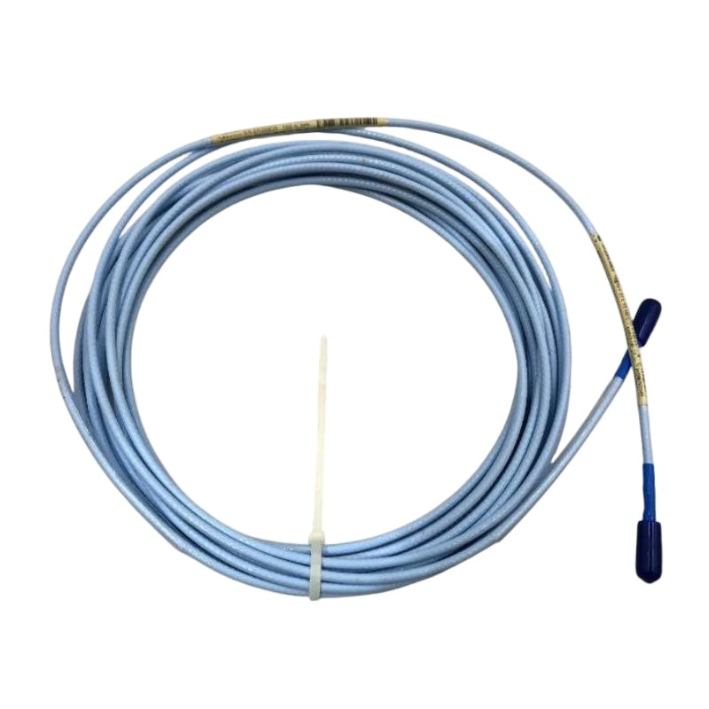
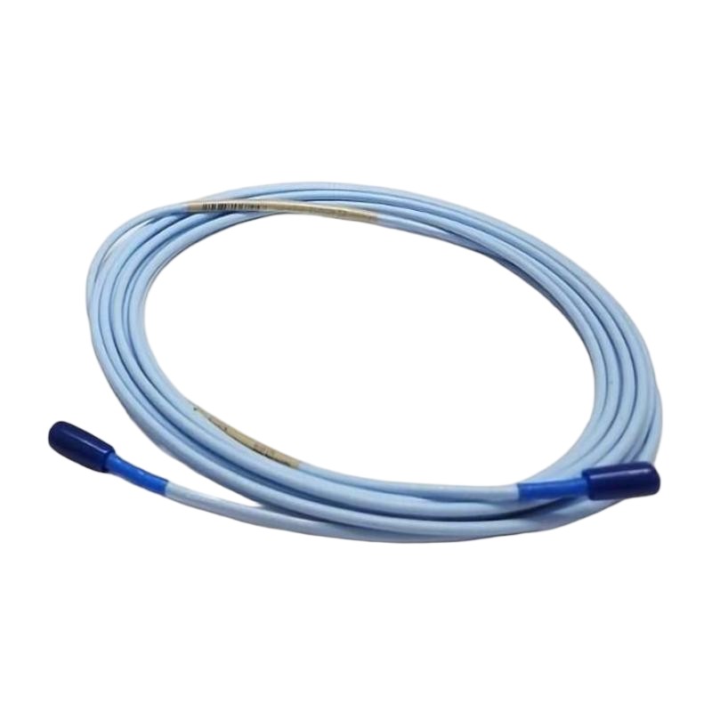
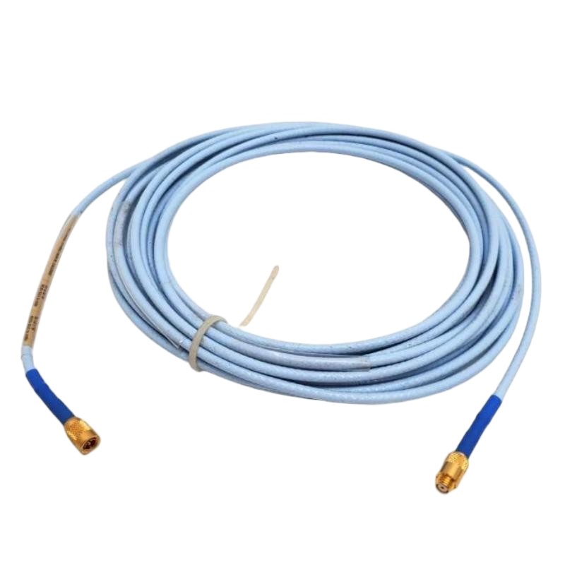
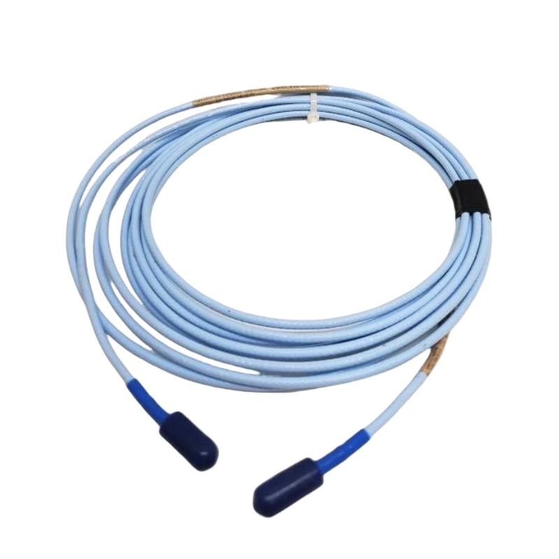
- Bently Nevada
- 164517-110-20-02-05
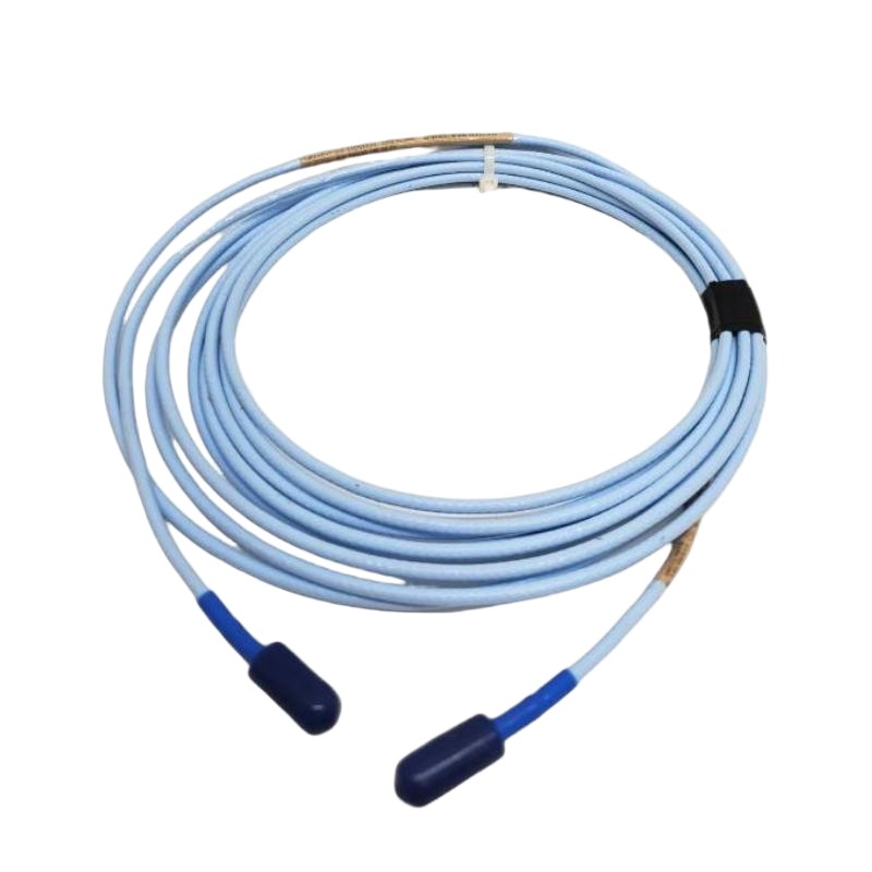
- 3300 Ceramic Capped Proximity Probe
- USA
- 2 meters
- 3 kg
- Xiamen, China
- New & In Stock
- T/T, PayPal, Western Union
- 1 Year
- 1-3 Working Days
- DHL, UPS, TNT, FedEx and EMS.
- 24-Hour Service
- COO
- 17
Our advantage

Global Logistics
We have a 10-year logistics and express cooperation agreement, so our products can be shipped to any place in the world.

Brand new and original
Our products are imported in bulk from the place of origin. Because of the cooperative relationship, our products are all original and 100% new.

24-hour service
We provide 7*24 hours service to our customers. We will be there whenever you need us.

Price advantage
All our products are priced very favorably because we have our own warehouse and supply.
| Company Information | |||
| [email protected] | |||
| Mobile | +8615980777398 | ||
| +8615980777398 | |||
| 15980777398 |
Product Overview
The Bently Nevada 164517-110-20-02-05 3300 Ceramic Capped Proximity Probe is a non-contact displacement sensor used in rotating machinery monitoring systems. It belongs to the 3300 Series proximity measurement family and is used to observe shaft movement relative to a fixed machine reference.
Unlike a conventional contact-type mechanical sensor, a proximity probe measures the position or movement of a conductive target without physically touching the rotating shaft. This makes the probe suitable for continuous monitoring of critical rotating equipment where direct access to the moving shaft is impractical.
The 164517-110-20-02-05 can form part of a complete proximity measurement channel together with a compatible extension cable and Proximitor-type signal-conditioning electronics. The resulting measurement can be used for shaft vibration, radial position, or other machinery displacement monitoring functions according to the installed system configuration.
For replacement work, the complete probe part number should be checked rather than selecting a probe based only on cable length or physical appearance. Probe characteristics, extension cable arrangement, target material, mounting dimensions, and associated monitoring electronics should all be considered.
Technical Specifications
| Parameter | Specification |
|---|---|
| Manufacturer | Bently Nevada |
| Model | 164517-110-20-02-05 |
| Product Family | 3300 Series |
| Product Type | Ceramic Capped Proximity Probe |
| Primary Function | Non-Contact Shaft Displacement Measurement |
| Measurement Principle | Eddy-Current Proximity Measurement |
| System Role | Machinery Vibration / Position Monitoring |
| Application | Rotating Machinery |
| Total Length | 2 meters |
| Shipping Weight | 3 kg |
Product Features
The 164517-110-20-02-05 is intended for proximity-based machinery measurements where continuous shaft displacement information is required.
Key characteristics include:
- Bently Nevada 3300 Series proximity probe
- Model 164517-110-20-02-05
- Ceramic-capped probe construction
- Non-contact measurement of conductive targets
- Suitable for rotating machinery monitoring
- Used with compatible proximity monitoring electronics
- Suitable for shaft vibration and displacement applications
- Supports continuous machinery condition monitoring
- Total probe assembly length of 2 meters
- Useful for maintenance and replacement of existing 3300 monitoring channels
Probe selection should take into account the complete measurement channel rather than the probe alone. Extension cable length and signal-conditioning hardware must correspond to the intended monitoring configuration.
Working Principle
The 164517-110-20-02-05 operates using an eddy-current proximity measurement principle. The probe establishes an electromagnetic field near the conductive machine target, typically a rotating shaft.
A simplified measurement path is:
Probe Driver → Proximity Probe → Conductive Shaft Target → Electrical Signal → Monitoring System
During operation, the probe and associated electronics generate a high-frequency electrical field at the sensing tip. When the conductive shaft moves closer to or farther away from the probe, the interaction between the electromagnetic field and target changes.
The measurement sequence can be summarized as:
-
Probe Excitation
The associated signal-conditioning electronics energize the proximity probe.
-
Electromagnetic Field
The probe produces an electromagnetic sensing field around its tip.
-
Target Interaction
The conductive shaft interacts with the field, producing a response related to the probe-to-target gap.
-
Shaft Movement
Radial or axial movement of the shaft changes this gap.
-
Signal Conversion
The associated electronics convert the probe response into a usable displacement signal.
-
Condition Monitoring
The resulting signal can be evaluated for shaft vibration, position, or other configured machinery measurements.
Because the probe does not need to contact the rotating shaft, it can continuously observe shaft movement without introducing mechanical contact between the sensor and rotating component.
Role in a 3300 Series Machinery Monitoring Channel
The 164517-110-20-02-05 represents the sensing element of a complete proximity measurement channel.
A typical arrangement can be represented as:
Rotating Shaft → Proximity Probe → Extension Cable → Proximitor / Signal Conditioner → Monitoring System
Each section has a different responsibility:
| System Element | Function |
|---|---|
| Rotating Shaft | Provides the conductive measurement target |
| Proximity Probe | Detects changes in probe-to-shaft gap |
| Extension Cable | Connects the probe to associated electronics |
| Proximitor / Signal Conditioner | Supplies excitation and conditions the probe signal |
| Monitoring System | Displays, analyzes, and records machinery condition |
This arrangement allows engineers to observe shaft movement without installing a contact sensor directly on the rotating component.
When troubleshooting a proximity channel, the probe should therefore not be tested in isolation. Cable condition, probe gap, mounting, target surface, signal-conditioning electronics, and monitoring-channel configuration can all affect the final measurement.
Industrial Applications
| Application | Typical Use |
|---|---|
| Steam Turbines | Shaft vibration and position monitoring |
| Gas Turbines | Rotating shaft condition monitoring |
| Compressors | Monitoring shaft dynamic behavior |
| Pumps | Detecting abnormal shaft movement |
| Turboexpanders | Continuous displacement monitoring |
| Generators | Monitoring rotor-related vibration |
| Industrial Turbomachinery | Shaft position and vibration measurement |
| Critical Rotating Equipment | Machinery protection and diagnostics |
The exact measurement function depends on the probe location and the configuration of the associated monitoring channel.
Installation and Maintenance
Correct probe installation is essential because the measurement depends directly on the relationship between the probe tip and the rotating target.
Recommended practices include:
- Confirm the complete 164517-110-20-02-05 part number.
- Verify compatibility with the existing 3300 Series monitoring channel.
- Confirm the required extension-cable arrangement.
- Inspect the probe body and ceramic cap before installation.
- Check the mounting thread and installation hardware.
- Verify the probe position relative to the shaft target.
- Establish the specified probe-to-target gap according to the applicable system configuration.
- Inspect the cable for cuts, crushing, or excessive bending.
- Keep the cable away from excessive heat and mechanical interference.
- Check connectors for contamination or damage.
- Verify the associated signal-conditioning electronics.
- Confirm correct channel identification.
- Compare the output with the expected machinery baseline.
- Monitor the signal during startup and normal operating conditions.
A sudden change in probe output should not automatically be attributed to probe failure. A changed probe gap, damaged cable, shaft condition, mounting movement, or signal-conditioning problem can produce similar symptoms.
Related Components
| Component | Function |
|---|---|
| Bently Nevada 164517-110-20-02-05 | Detects shaft displacement |
| 3300 Series Proximitor / Signal Conditioner | Provides probe excitation and signal conditioning |
| Extension Cable | Connects probe and associated electronics |
| Monitoring System | Processes machinery measurement data |
| Rotating Shaft | Conductive measurement target |
| Probe Mounting Hardware | Maintains the required sensor position |
| Vibration Monitoring Channel | Evaluates shaft dynamic behavior |
| Machinery Protection System | Uses monitored conditions for protective functions |
Recommended Related Models
| Model / Product Family | Product Type | Typical Application |
|---|---|---|
| Bently Nevada 164517-110-20-02-05 | 3300 Ceramic Capped Proximity Probe | Shaft displacement monitoring |
| Bently Nevada 3300 Series Proximity Probes | Proximity Sensor | Rotating machinery monitoring |
| Bently Nevada 3300 Series Extension Cables | Extension Cable | Probe-to-electronics connection |
| Bently Nevada 3300 Series Proximitor Systems | Signal Conditioner | Proximity signal processing |
| Bently Nevada 3300 Series Monitoring Components | Machinery Monitoring Hardware | Vibration and shaft-condition monitoring |
Key Advantages
- Bently Nevada 3300 Series proximity probe.
- Model 164517-110-20-02-05.
- Ceramic-capped construction.
- Non-contact shaft displacement measurement.
- Suitable for rotating machinery condition monitoring.
- Supports shaft vibration and position measurement applications.
- Compatible with an appropriate 3300 Series proximity measurement architecture.
- 2-meter total length.
- Useful for maintenance and replacement of established machinery monitoring channels.
Technical FAQs
Why must the probe gap be checked when replacing a 164517-110-20-02-05?
The proximity measurement depends on the distance between the sensing tip and conductive shaft target. If the replacement probe is installed at an incorrect gap, the resulting output can differ from the expected measurement even when the probe itself is functioning correctly.
What can cause an intermittent proximity-probe signal?
Potential causes include cable damage, loose connections, probe movement, mounting problems, electrical interference, changes in the probe-to-target relationship, or an issue in the associated signal-conditioning electronics. The complete measurement channel should be checked before replacing the probe.
Why is the conductive shaft surface important to this type of measurement?
The probe detects changes in the electromagnetic interaction with the conductive target. Surface condition, target material, geometry, and mechanical condition can therefore influence the measurement and should be considered when evaluating unusual readings.
How can technicians determine whether an abnormal reading originates from the probe or the machinery?
Compare the probe signal with other available measurements and operating conditions, including shaft vibration, speed, temperature, and machine load. If the abnormal signal appears without corresponding changes in other machine parameters, the probe, cable, mounting, or signal-conditioning path should receive closer attention.