
NewsNEWCENTER
Featured products
Contact Us
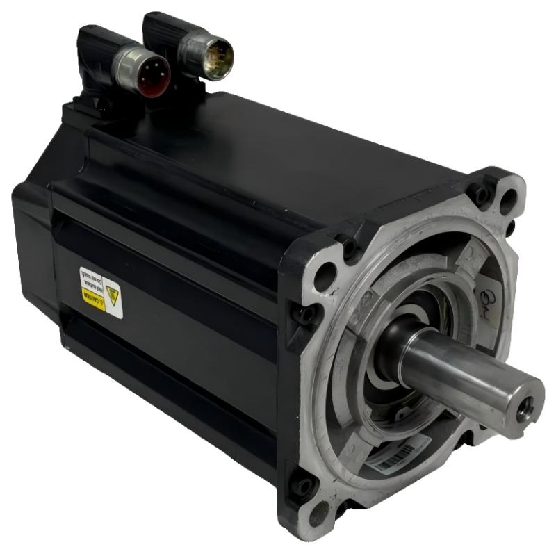
Allen Bradley MPL-A540K-SK74AA Servo Motor Troubleshooting Guide
2026-10-09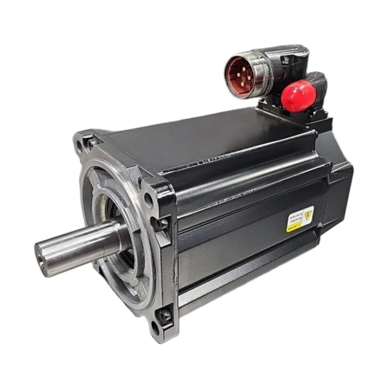
The Allen Bradley MPL-A540K-SK74AA Servo Motor troubleshooting process should examine the complete motion-control system, including the servo drive, motor power circuit, feedback cable, mechanical load, and controller configuration. Symptoms such as failure to start, unexpected drive faults, vibration, overheating, or inaccurate positioning do not automatically indicate motor failure. A structured diagnostic sequence helps identify the actual fault and avoid unnecessary component replacement.
Understanding the MPL-A540K-SK74AA Servo System
A servo motor operates as part of a closed-loop motion-control system. The controller generates motion commands, the drive supplies controlled electrical power, and feedback information allows the drive to regulate the motor’s response.
Motion Controller
       ↓
Servo Drive
       ↓
Motor Power Circuit
       ↓
MPL-A540K-SK74AA
       ↓
Mechanical Load

Motor Feedback ─────→ Servo Drive
Drive Status ───────→ Controller
A fault anywhere in this chain may interrupt motion or degrade performance. Troubleshooting should identify where the expected behavior first diverges from the actual behavior.
Common MPL-A540K-SK74AA Servo Motor Problems
- Motor does not rotate when a motion command is issued.
- Servo drive reports a motor or feedback-related fault.
- Motor starts but stops unexpectedly.
- Positioning accuracy is inconsistent.
- Motor vibration or abnormal noise occurs.
- Motor or drive temperature rises excessively.
- Axis movement is rough or unstable.
- Motor direction does not match the commanded direction.
- Faults occur intermittently during acceleration or deceleration.
Common Fault Causes and Initial Checks
| Symptom | Possible Cause | Initial Diagnostic Check |
|---|---|---|
| Motor will not start | Drive inhibit, missing enable, wiring fault | Review drive status and enable conditions |
| Feedback fault | Loose connector, damaged cable, incompatibility | Inspect feedback circuit |
| Excessive vibration | Misalignment, tuning issue, mechanical looseness | Inspect mounting and load |
| Position error | Incorrect scaling, excessive load, tuning issue | Compare command and feedback |
| Overtemperature | Overload, restricted cooling, excessive duty | Review load and operating conditions |
| Intermittent shutdown | Loose wiring, intermittent fault, unstable supply | Review fault history and connections |
MPL-A540K-SK74AA Diagnostic Flow
Servo Axis Fault
       ↓
Read Drive Fault Code
       ↓
Check Enable / Safety Status
       ↓
Drive Ready?
    ↙       ↘
   NO       YES
   ↓         ↓
Check Drive  Check Motor
Status       Power / Feedback
                ↓
          Electrical Path OK?
             ↙       ↘
            NO       YES
            ↓         ↓
      Repair Wiring  Inspect Load
                      / Mechanics
                          ↓
                   Check Parameters
                          ↓
                    Controlled Test
Step-by-Step Troubleshooting Procedure
1. Read the Servo Drive Fault Information
Record the displayed fault code, fault description, operating state, and conditions immediately before the event. Use the documentation for the installed drive to interpret the fault. Avoid clearing repeated faults without recording their details, because the fault history may be important for diagnosis.
2. Check Enable Signals and Safety Conditions
If the motor does not move, verify that the drive is ready and that all required enable, interlock, and safety conditions are satisfied. A disabled axis may appear to have a motor problem even when the motor and power wiring are functioning normally.
3. Inspect Motor Power Connections
Under the site’s approved isolation procedure, inspect the motor power cable, connectors, grounding, and associated drive connections. Look for loose terminals, damaged insulation, contamination, or signs of overheating.
Never disconnect motor power or feedback connectors while energized unless the specific equipment documentation explicitly permits the action.
4. Inspect the Feedback Circuit
Check that the feedback cable is compatible with the motor and drive and that its connectors are properly seated. Inspect for cable damage, bent contacts, contamination, and excessive mechanical strain.
If a feedback fault persists, follow the drive manufacturer’s approved diagnostic procedure. Do not assume that the feedback device is defective until cable and configuration problems have been excluded.
5. Check Mechanical Loading
Abnormal vibration, high following error, or excessive motor current may result from a binding mechanism, coupling misalignment, excessive load, or damaged mechanical components.
- Inspect coupling alignment.
- Check mounting bolts and mechanical rigidity.
- Look for signs of binding in the driven mechanism.
- Confirm that the load is within the machine’s designed operating limits.
- Investigate unusual bearing noise or shaft resistance using an approved maintenance procedure.
6. Review Servo Parameters and Tuning
If the electrical and mechanical checks are satisfactory, review motor identification, feedback configuration, scaling, motion limits, and servo tuning. Incorrect tuning may cause oscillation, overshoot, noise, or unstable positioning.
Change parameters only in a controlled manner and document the original values so that changes can be reversed if necessary.
Diagnosing Positioning and Motion Stability Problems
When the motor moves but does not follow commands accurately, compare the commanded position with the actual feedback position. Review following error, acceleration demands, load conditions, and mechanical backlash.
Positioning Error
       ↓
Compare Command and Feedback
       ↓
Is Feedback Valid?
    ↙          ↘
   NO          YES
   ↓            ↓
Check Cable   Inspect Load
and Feedback  and Alignment
                  ↓
             Review Tuning
                  ↓
             Retest Motion
Positioning errors should not be corrected solely by increasing servo gains. First confirm that the feedback data is valid and the mechanics are sound.
Illustrative MPL-A540K-SK74AA Diagnostic Record
The following is an illustrative maintenance example, not a verified customer case or a motor-specific diagnostic specification.
Reported Symptom:
Intermittent following error during acceleration

Drive Fault History:
Following-error events recorded

Motor Power Wiring:
No visible damage

Feedback Connection:
Secure after inspection

Mechanical Check:
Load movement shows increased resistance

Diagnostic Direction:
Investigate mechanical binding and load conditions
before changing tuning parameters or replacing the motor.
This example highlights the importance of checking the mechanical load when motion faults occur primarily during acceleration.
Repair and Replacement Considerations
Motor replacement should be considered only after the drive, feedback circuit, power wiring, mechanical system, and configuration have been evaluated. Some faults that appear to originate in the motor are caused by external components or incorrect application settings.
- Place the machine in a safe maintenance state.
- Isolate electrical and mechanical energy according to site procedures.
- Record the motor and drive identification.
- Document the existing wiring and mounting arrangement.
- Inspect connectors, cables, shaft, and mounting surfaces.
- Correct any identified external fault.
- If replacement is justified, use a compatible motor and approved installation procedure.
- Restore wiring and verify grounding.
- Confirm drive configuration and feedback recognition.
- Perform controlled motion testing before returning the machine to service.
Post-Repair Testing Checklist
- Drive reports the expected ready status.
- No persistent motor or feedback faults remain.
- Motor direction is correct.
- Mechanical movement is smooth.
- Position feedback corresponds to commanded movement.
- Acceleration and deceleration are stable.
- Motor and drive temperatures remain within applicable limits.
- Safety interlocks and travel limits operate correctly.
- Machine functions are validated under controlled conditions.
Allen Bradley MPL-A540K-SK74AA Troubleshooting FAQs
Why does the MPL-A540K-SK74AA not start?
Check the drive-ready state, enable conditions, safety interlocks, fault history, motor power wiring, and feedback connection before assuming that the motor has failed.
What causes servo feedback faults?
Possible causes include loose or damaged feedback cables, connector problems, incompatible components, electrical interference, or incorrect drive configuration.
Why does the servo motor vibrate?
Potential causes include mechanical misalignment, a loose mounting structure, load binding, incorrect tuning, or unreliable feedback. Inspect the mechanics and feedback path before adjusting control parameters.
When should the servo motor be replaced?
Replacement should be considered when diagnostic evidence supports a motor-side fault after the drive, cables, feedback interface, mechanical load, and configuration have been checked.
Can I test the motor by disconnecting its cables while running?
No. Disconnecting motor power or feedback connections during operation can create electrical hazards, equipment damage, and uncontrolled motion. Follow the approved isolation and testing procedures.
Technical Summary
Troubleshooting the Allen Bradley MPL-A540K-SK74AA Servo Motor requires coordinated checks of drive status, enable signals, power wiring, feedback, mechanical loading, and motion parameters. Recording fault history and identifying the first point where expected behavior is lost helps technicians isolate the real cause. A systematic diagnostic process reduces unnecessary motor replacements and supports a safer, more reliable return to operation.