
NewsNEWCENTER
Featured products
Contact Us
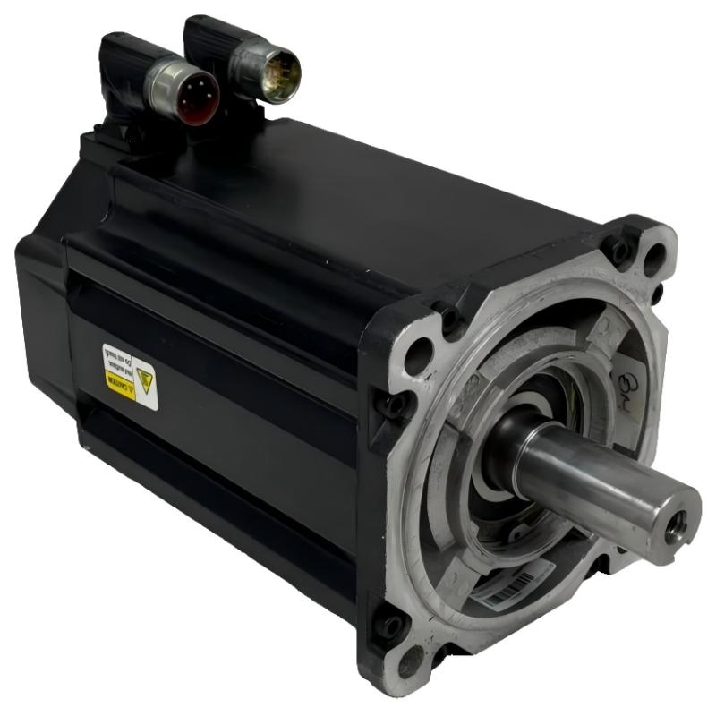
Allen Bradley MPL-A540K-SK74AA Servo Motor Installation Guide
2026-10-09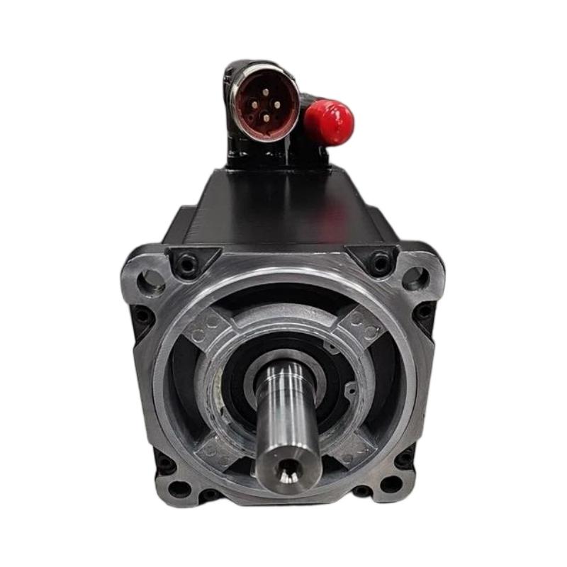
The Allen Bradley MPL-A540K-SK74AA Servo Motor installation process involves mechanical mounting, shaft alignment, power and feedback wiring, drive configuration, and controlled commissioning. As part of an industrial motion-control system, the motor must be correctly matched to its compatible servo drive and feedback interface. Following a structured installation procedure helps improve positioning accuracy, motion stability, and long-term operating reliability.
Allen Bradley MPL-A540K-SK74AA Servo Motor Overview
The MPL-A540K-SK74AA belongs to the Allen Bradley Kinetix MP-series servo motor family. Servo motors are designed for applications requiring controlled speed, torque, acceleration, and positioning. They are commonly integrated into automated machinery through a compatible servo drive and a controller that executes motion commands.
A typical motion-control arrangement follows this signal path:
PLC / Motion Controller
          ↓
      Servo Drive
          ↓
MPL-A540K-SK74AA Servo Motor
          ↓
 Mechanical Load / Machine Axis

Motor Feedback ─────→ Servo Drive
Before installation, confirm the complete motor catalog number, connector configuration, electrical ratings, feedback compatibility, and applicable drive requirements. Do not assume that a similar-looking motor or connector is interchangeable.
Installation Preparation and Safety
Before mounting the Allen Bradley MPL-A540K-SK74AA, review the machine drawings and the applicable motor and drive documentation. Servo systems can produce hazardous voltages and unexpected mechanical movement.
- Verify the motor catalog number and nameplate information.
- Confirm compatibility with the selected servo drive.
- Inspect the housing, shaft, connectors, and mounting surfaces.
- Check that the machine is isolated from hazardous energy.
- Confirm the motor’s required mounting orientation and available clearance.
- Prepare suitable power and feedback cables.
- Verify protective grounding and cable-shielding requirements.
- Ensure the driven mechanism can move safely during commissioning.
MPL-A540K-SK74AA Mechanical Mounting
Mount the servo motor on a rigid machine surface that can withstand the expected operating loads and vibration. The motor flange and mounting face should be clean, flat, and free from debris that could affect alignment.
Shaft Alignment and Coupling
Misalignment between the motor shaft and the driven mechanism can increase bearing loads, generate vibration, and shorten service life. Check coupling alignment using the method specified by the machine manufacturer. Do not use the motor shaft to force misaligned components into position.
- Verify the coupling type and shaft dimensions.
- Check angular and parallel alignment.
- Confirm that the driven load rotates freely where the machine design permits.
- Prevent excessive radial or axial loads on the motor shaft.
- Secure all mounting hardware to the specified torque.
Allen Bradley MPL-A540K-SK74AA Wiring Guide
Servo motor wiring typically includes motor power connections, protective grounding, and feedback connections. The exact connector assignments and cable requirements must be verified against the documentation for the specific motor and compatible drive.
Motor Power Connections
Use the correct motor power cable and approved connectors. Check conductor condition, connector engagement, and grounding continuity before enabling the drive. Keep motor power cables routed separately from sensitive signal wiring where practical.
Feedback and Encoder Connections
The servo drive uses feedback information to regulate motor motion. Incorrect feedback wiring, incompatible feedback hardware, or a damaged cable can cause drive faults, unstable operation, or failure to establish servo control.
- Verify the correct feedback cable and connector.
- Inspect connectors for bent contacts or contamination.
- Secure cable connections according to the applicable instructions.
- Keep feedback cables away from major sources of electrical interference.
- Confirm that the drive recognizes the motor and feedback system.
Servo Drive Configuration and Motion Setup
After the motor is mounted and wired, configure the compatible servo drive and motion controller. Use the correct motor identification and approved parameter set rather than copying settings from a different motor model.
- Confirm the motor and drive catalog numbers.
- Verify the motor feedback connection.
- Select the correct motor configuration in the engineering software.
- Configure the motion axis and feedback scaling.
- Check travel limits, direction, and machine interlocks.
- Review acceleration, deceleration, and speed limits.
- Verify fault handling and emergency-stop behavior.
MPL-A540K-SK74AA Commissioning Procedure
Commissioning should proceed in stages, beginning with inspection and configuration checks before enabling powered movement.
Mechanical Inspection
        ↓
Power / Feedback Wiring Check
        ↓
Drive Configuration
        ↓
Drive Diagnostic Review
        ↓
Controlled Servo Enable
        ↓
Direction Verification
        ↓
Low-Speed Motion Test
        ↓
Position / Feedback Verification
        ↓
Application-Level Test
Initial Power-Up
Before applying power, verify that all wiring is complete and the machine is in a safe condition. Check drive diagnostics and resolve any configuration or feedback faults before attempting motion.
Direction and Low-Speed Testing
Use an approved commissioning mode to verify the direction of movement at a controlled speed. Confirm that the motor direction corresponds to the machine coordinate system and that mechanical travel limits function correctly.
Motion Performance Verification
After basic movement is confirmed, test the intended motion profile under controlled conditions. Observe positioning accuracy, acceleration, deceleration, vibration, noise, and drive status. Increase operating demands gradually and remain within the machine’s approved limits.
Common Installation Mistakes to Avoid
- Using an incompatible servo drive or feedback cable.
- Assuming connector pin assignments without checking documentation.
- Leaving power or feedback connectors incompletely seated.
- Routing feedback cables alongside high-interference conductors.
- Ignoring shaft alignment or excessive mechanical load.
- Enabling motion before checking travel limits and interlocks.
- Using parameters copied from another motor without verification.
Representative Commissioning Case
In a representative machine commissioning scenario, a newly installed servo motor produces a drive feedback fault during startup. The technician checks the motor power connections and confirms that the mechanical installation is secure. Further inspection identifies a feedback connector that is not fully seated. After correcting the connection and checking the drive configuration, the fault clears and controlled low-speed testing can proceed.
This example illustrates why feedback wiring and drive diagnostics should be checked before concluding that the motor itself is defective.
Allen Bradley MPL-A540K-SK74AA Installation FAQs
What is the MPL-A540K-SK74AA Servo Motor used for?
It is an industrial servo motor intended for motion-control applications that require controlled speed, torque, or positioning as part of a compatible Allen Bradley motion system.
Can any Allen Bradley servo drive operate this motor?
No. Drive compatibility depends on the motor’s electrical characteristics, feedback interface, connector arrangement, and supported configuration. Confirm compatibility using the applicable product documentation.
Why is feedback wiring important?
The drive relies on feedback to regulate motor motion. An incorrect or unreliable feedback connection can prevent startup or cause motion faults.
What should be checked before the first motion test?
Verify mounting, shaft alignment, power wiring, feedback connections, drive configuration, travel limits, safety interlocks, and the machine’s safe operating condition.
Technical Summary
Successful installation of the Allen Bradley MPL-A540K-SK74AA Servo Motor depends on correct drive compatibility, precise mechanical mounting, reliable power and feedback connections, and systematic commissioning. By validating the mechanical system, electrical interfaces, drive configuration, and motion response in sequence, technicians can reduce startup faults and establish a reliable servo axis.