

ProductPRODUCT
Featured products
Contact Us
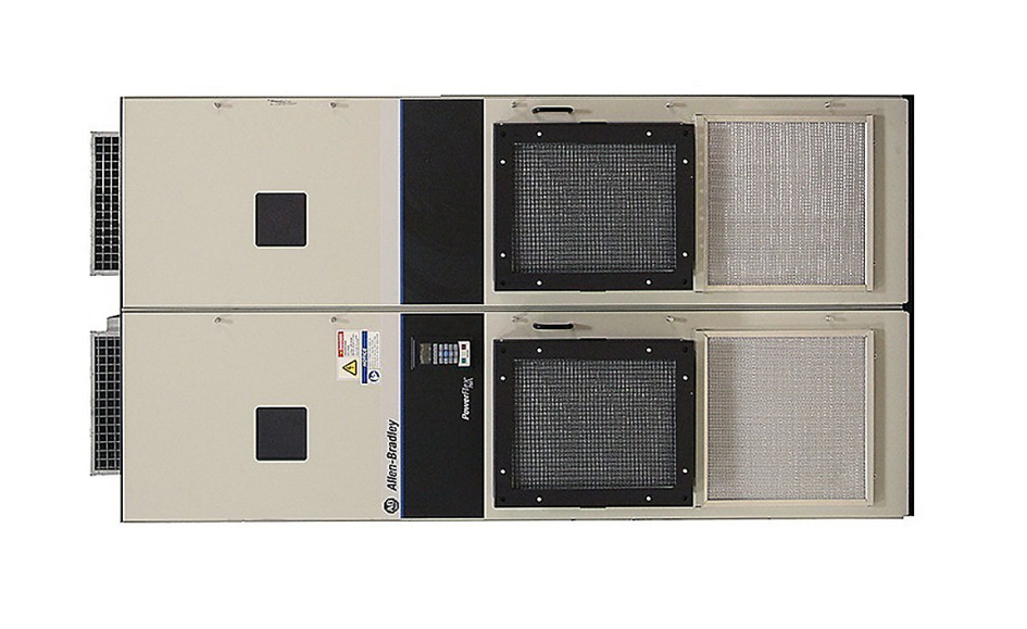
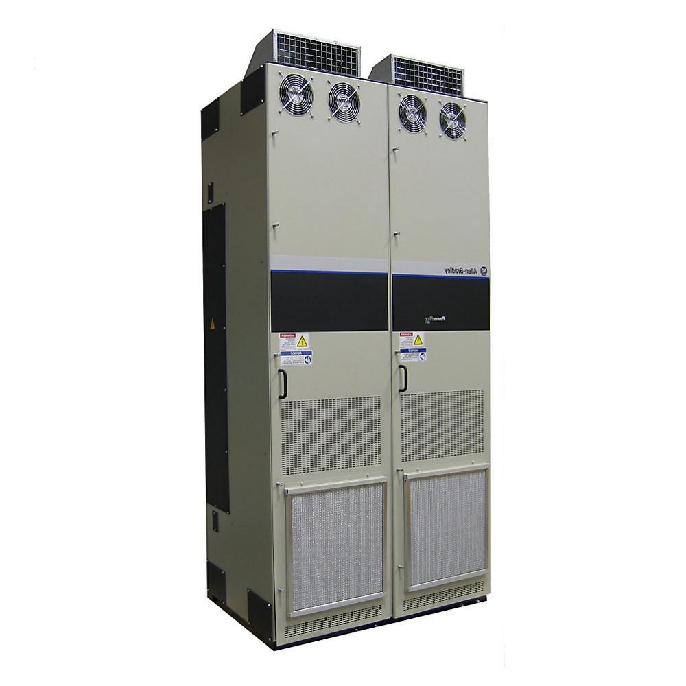
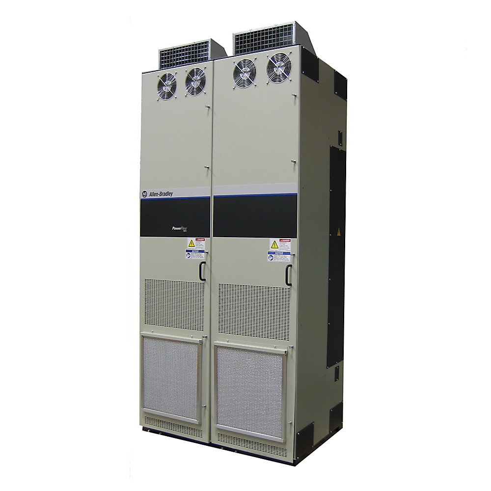
- Allen Bradley
- 20J1F3C2K8LNDNNNNN
- PowerFlex AC Drive
- USA
- 1,100–1,500 × 600–900 × 400–550 mm
- 230kg
- Xiamen, China
- New & In Stock
- T/T, PayPal, Western Union
- 1 Year
- 1-3 Working Days
- DHL, UPS, TNT, FedEx and EMS.
- 24-Hour Service
- COO
- 2
Our advantage

Global Logistics
We have a 10-year logistics and express cooperation agreement, so our products can be shipped to any place in the world.

Brand new and original
Our products are imported in bulk from the place of origin. Because of the cooperative relationship, our products are all original and 100% new.

24-hour service
We provide 7*24 hours service to our customers. We will be there whenever you need us.

Price advantage
All our products are priced very favorably because we have our own warehouse and supply.
| Company Information | |||
| [email protected] | |||
| Mobile | +8615980777398 | ||
| +8615980777398 | |||
| 15980777398 |
1. Product Identification
| Parameter | Specification |
|---|---|
| Brand | Allen-Bradley |
| Model | 20J1F3C2K8LNDNNNNN |
| Product Series | PowerFlex 750 |
| Product Family | PowerFlex 750 Bus Supplies |
| Product Type | Air-Cooled 750 Bus Supply |
| Main Function | DC-bus power supply |
| Configuration | F3 / C2K8 configuration |
| Cooling Method | Air cooled |
| Electrical Class | 400 V AC class |
| Installation | Industrial cabinet / drive system |
| Application | Common DC-bus and multi-drive systems |
| Product Status | Discontinued |
| Direct Replacement Reference | 20JEF3C2K8LNDNNNNN |
| Approx. Dimensions | 1,100–1,500 mm H × 600–900 mm W × 400–550 mm D* |
| Approx. Weight | 140–230 kg* |
*Dimensions and weight are preliminary engineering estimates. They should not be treated as certified mechanical specifications for cabinet fabrication or transportation planning. The actual configured unit drawing and nameplate should be used for final dimensions and weight.
2. Product Introduction
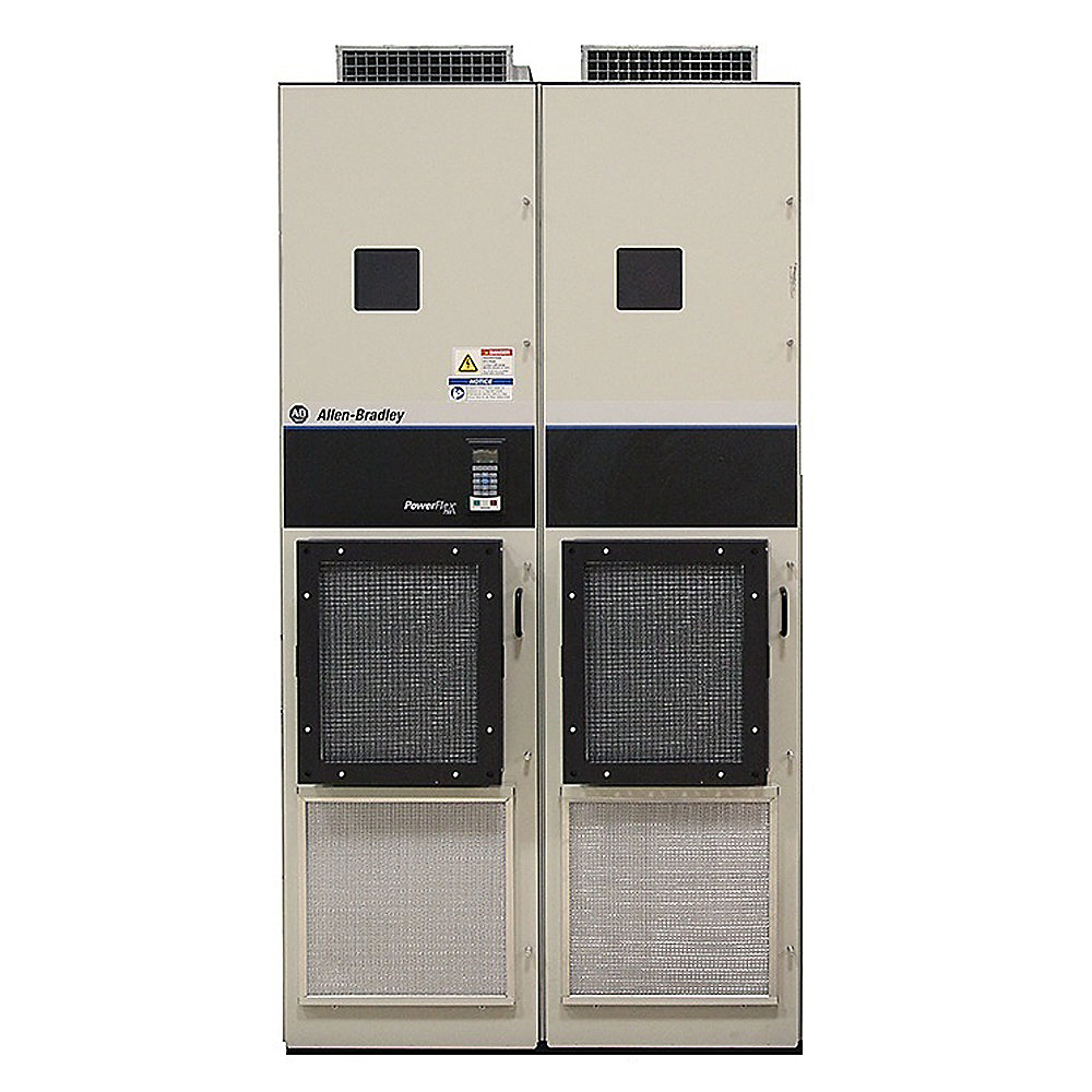
The Allen-Bradley 20J1F3C2K8LNDNNNNN is a high-power PowerFlex 750 Bus Supply intended for industrial drive systems that use a common DC-bus architecture.
Rather than operating as a conventional standalone motor inverter, this type of equipment functions as the power-supply section of a larger drive system.
Its primary role is to provide controlled DC-bus power for compatible PowerFlex drive sections and other components forming part of a coordinated high-power motion or process system.
The catalog number is specifically identified as an Air-Cooled 750 Bus Supply, placing it within the high-power bus-supply portion of the PowerFlex 750 product family.
The 20J1F3C2K8LNDNNNNN is particularly relevant to applications where several motors or drive sections need to operate together and where the machine designer wants a centralized power-conversion architecture rather than completely independent drive power supplies.
This type of architecture is commonly considered for large conveyors, cranes, hoists, winding machinery, material-handling equipment, process machinery, and other high-power industrial systems.
3. Product Series
Series: PowerFlex 750 Bus Supply
The 20J1F3C2K8LNDNNNNN belongs to the PowerFlex 750 Bus Supply family.
The 20J1F3 family contains numerous configurations covering different power levels and electrical arrangements. Other catalog listings in the same family include C1K2, C1K4, C2K1, C302, C367, C540, C650, C770, C920, D1K0, D1K3, and other configurations.
This means that the C2K8 version should be viewed as one member of a broader family of high-power bus-supply equipment rather than as an independent product with no related configurations.
4. Main Function
The main purpose of the 20J1F3C2K8LNDNNNNN is to provide electrical power to the DC bus of a coordinated PowerFlex drive system.
A simplified system arrangement can be understood as:
Incoming AC Power
↓
PowerFlex 750 Bus Supply
↓
Common DC Bus
↓
Multiple Drive Sections
↓
Multiple Motors
The bus supply is therefore positioned at the front end of the drive architecture.
This arrangement is useful when the machine contains several motors whose electrical operation is closely related.
5. Common DC-Bus Architecture
A common DC-bus system allows multiple compatible drive sections to share a centralized DC power source.
This approach can be particularly useful in large industrial machines.
For example, a production line may have several motors operating simultaneously.
One motor may accelerate while another is operating at constant speed.
A third motor may be decelerating and returning energy to the DC bus.
A centralized bus architecture allows these operating conditions to be managed as part of one coordinated electrical system.
This can be more appropriate for large multi-motor machinery than treating every motor as a completely independent installation.
6. Electrical Characteristics
The F3 configuration is associated with the 400 V AC industrial voltage class.
The exact installation voltage must always be verified against the complete machine electrical design.
A proper engineering review should include:
- Incoming AC voltage.
- Line frequency.
- Transformer capacity.
- Short-circuit current.
- Grounding arrangement.
- Upstream protection.
- Cable dimensions.
- DC-bus requirements.
- Connected drive capacity.
- Regenerative operating conditions.
- Cabinet thermal capacity.
7. Air-Cooled Design
The exact model is identified as an Air-Cooled 750 Bus Supply.
Air cooling is a practical approach for large industrial power-conversion equipment.
It avoids the need for an external liquid-cooling circuit, coolant reservoir, pump, and heat exchanger.
At the same time, the cabinet design becomes very important.
The installation must provide sufficient airflow around the equipment.
Air passages should not be blocked by cables, cabinet partitions, filters, or other equipment.
The surrounding environment should also be evaluated for dust, oil mist, humidity, corrosive gases, and elevated ambient temperature.
For large power equipment, cooling is not simply a convenience feature.
It is a major part of system reliability.
8. Detailed Parameter Table
| Technical Parameter | Specification |
|---|---|
| Brand | Allen-Bradley |
| Model | 20J1F3C2K8LNDNNNNN |
| Series | PowerFlex 750 |
| Family | PowerFlex 750 Bus Supplies |
| Product Description | Air-Cooled 750 Bus Supply |
| Product Type | DC-bus power supply |
| Voltage Class | 400 V AC |
| Cooling | Air cooled |
| Architecture | Common DC bus |
| Main Application | High-power multi-drive systems |
| Regenerative Applications | Suitable |
| Installation | Industrial cabinet |
| Duty | Heavy industrial |
| Approx. Height | 1,100–1,500 mm* |
| Approx. Width | 600–900 mm* |
| Approx. Depth | 400–550 mm* |
| Approx. Weight | 140–230 kg* |
| Mechanical Installation | Cabinet / industrial equipment |
| Thermal Management | Forced-air cooling |
| Product Status | Discontinued |
| Listed Direct Replacement | 20JEF3C2K8LNDNNNNN |
*Estimated planning range. Verify the final mechanical drawing and nameplate before enclosure manufacturing, lifting, shipping, or floor-load calculations.
9. Mechanical Dimensions
For preliminary equipment layout, the 20J1F3C2K8LNDNNNNN can be planned around the following approximate envelope:
| Mechanical Item | Approximate Value |
|---|---|
| Height | 1,100–1,500 mm |
| Width | 600–900 mm |
| Depth | 400–550 mm |
| Weight | 140–230 kg |
| Cooling | Air cooled |
| Mounting | Industrial cabinet |
| Service Access | Front and equipment-side clearance |
| Cable Space | Additional installation clearance required |
| Ventilation | Required |
| Lifting | Industrial lifting equipment recommended |
These figures are intended for preliminary planning only.
The exact mechanical configuration can depend on the complete equipment arrangement and associated options.
For a new cabinet, the final engineering drawing should always take precedence over an estimated envelope.
10. Weight and Handling
The estimated equipment weight is approximately 140–230 kg for planning purposes.
This is heavy industrial electrical equipment and should not be treated as a manually movable component.
Before transportation or installation, the actual equipment weight should be confirmed.
Handling arrangements should take into account:
- Forklift capacity.
- Crane capacity.
- Lifting points.
- Center of gravity.
- Cabinet structure.
- Floor loading.
- Transportation restraints.
- Installation orientation.
- Service access.
The lifting procedure should be designed around the actual equipment configuration rather than relying solely on a catalog estimate.
11. Main Applications
11.1 Large Conveyor Systems
Large conveyor systems are a natural application for centralized drive power.
A conveyor can contain several motors distributed across the machine.
A common DC-bus architecture allows these motors to operate as coordinated drive sections.
Typical applications include:
- Bulk-material conveyors.
- Mining conveyors.
- Port conveyors.
- Production-line conveyors.
- Warehouse transfer systems.
- Long-distance material-handling equipment.
11.2 Cranes
Cranes frequently operate with changing power direction.
During lifting, the motors consume electrical power.
During controlled lowering, the motors can enter regenerative operation.
This makes cranes a demanding application for the electrical power system.
A centralized bus-supply architecture can provide a suitable foundation for coordinated crane-drive systems.
11.3 Hoists
Hoisting systems combine high torque, large mechanical loads, acceleration, deceleration, and frequent direction changes.
These characteristics make the management of regenerative energy particularly important.
The PowerFlex 750 bus-supply concept is therefore well suited to large hoisting installations where several drive sections operate together.
11.4 Winding Machines
Winding and unwinding machinery can switch frequently between motoring and generating conditions.
The motors may accelerate a roll, maintain tension, decelerate the roll, or control material speed.
A common DC-bus arrangement can support this type of coordinated operation.
11.5 Paper and Film Processing
Paper, film, foil, cable, and similar continuous-web processes frequently require multiple synchronized motors.
A common bus can provide a centralized electrical architecture for these coordinated sections.
The system can be designed around the operating requirements of the complete production line rather than individual motors alone.
11.6 Metal Processing
Large metal-processing systems may contain multiple high-power motors.
Rolling, feeding, tension control, cutting, and material-handling sections can all require coordinated motor control.
A centralized bus architecture can therefore be useful in these installations.
11.7 Test Stands and Dynamometers
Test equipment can generate large amounts of regenerative energy because the motor is repeatedly accelerated and decelerated.
A bus-supply system can provide a centralized electrical architecture for these high-cycle operating conditions.
11.8 Large Machine Tools
Large machine tools can include multiple high-power axes and auxiliary motors.
A common DC-bus architecture can be considered when several motor sections must operate together and the machine has substantial braking or regenerative requirements.
12. Regenerative Energy Applications
One of the important reasons for using a sophisticated bus-supply architecture is regenerative operation.
Regeneration occurs when mechanical energy is returned to the electrical system.
Typical conditions include:
- Rapid deceleration.
- Lowering a heavy load.
- Braking high-inertia machinery.
- Unwinding material.
- Overhauling loads.
- High-speed stopping.
- Repeated acceleration/deceleration cycles.
In these conditions, the motors can temporarily act as generators.
The resulting electrical energy enters the DC-bus system.
The complete system must then provide a suitable method of handling that energy.
This is why the selection of a bus supply cannot be based only on average motor power.
Peak regenerative power and operating-cycle characteristics must also be considered.
13. Advantages
13.1 Centralized Power Architecture
The primary advantage is the ability to establish a centralized electrical power architecture for multiple drive sections.
This is particularly useful in large machines where several motors operate as one coordinated system.
13.2 Common DC-Bus Operation
A common DC bus allows multiple compatible drive sections to share the same DC power infrastructure.
This can reduce unnecessary duplication in the overall power-conversion architecture.
13.3 Suitable for Multi-Motor Systems
The bus-supply concept is especially appropriate when several motors need to operate simultaneously.
The machine can be designed around one coordinated electrical system instead of several completely independent drive installations.
13.4 Regenerative Energy Management
The common-bus architecture can be useful for machines that frequently regenerate energy.
This is especially important in cranes, hoists, winders, unwinders, and high-inertia machinery.
13.5 High-Power Industrial Use
The PowerFlex 750 bus-supply family is intended for demanding industrial applications.
It is more appropriate for large coordinated machinery than for small standalone motor-control tasks.
13.6 Air-Cooled Construction
The air-cooled design avoids the complexity of a dedicated liquid-cooling system.
For a properly designed cabinet, forced-air cooling can provide a practical maintenance approach.
13.7 System Integration
The bus supply forms part of a larger PowerFlex architecture.
This makes it suitable for applications where the drive system must be integrated into a larger industrial automation and control environment.
14. Typical System Configuration
A simplified industrial arrangement can be represented as:
Three-Phase AC Supply
↓
Input Protection and Switching
↓
20J1F3C2K8LNDNNNNN
↓
Common DC Bus
↓
Drive Section A → Motor A
↓
Drive Section B → Motor B
↓
Drive Section C → Motor C
↓
Drive Section D → Motor D
This architecture is particularly useful when the individual motors are part of one machine or production process.
15. Engineering Considerations
| Engineering Parameter | Recommended Check |
|---|---|
| Incoming Voltage | Confirm 400 V AC class |
| Frequency | Confirm plant supply frequency |
| Transformer | Verify sufficient capacity |
| Short-Circuit Current | Confirm protection compatibility |
| DC Bus | Verify complete bus architecture |
| Connected Drives | Confirm compatibility |
| Motor Power | Calculate total operating load |
| Peak Power | Check acceleration requirements |
| Regenerative Power | Check braking and deceleration |
| Ambient Temperature | Confirm thermal requirements |
| Cabinet Cooling | Provide sufficient airflow |
| Altitude | Check installation requirements |
| Grounding | Verify complete grounding system |
| EMC | Review cable routing and shielding |
| Cabinet Size | Allow installation and service space |
| Weight | Verify actual equipment mass |
| Mechanical Drawing | Required before fabrication |
16. Five Closely Related Models
The following models are suitable comparison products within the same PowerFlex 750 Bus Supply family.
They should not be treated as automatic drop-in replacements. The complete catalog number, electrical rating, configuration suffixes, mechanical arrangement, and system requirements must be checked before substitution. The catalog family includes these and other related air-cooled 750 bus-supply configurations.
| Model | Product Type | Voltage Class | Cooling | Application | Approx. Dimensions | Approx. Weight |
|---|---|---|---|---|---|---|
| 20J1F3C2K1LNDNNNNN | PowerFlex 750 Bus Supply | 400 V AC class | Air cooled | High-power common DC bus | 1,100–1,500 × 600–900 × 400–550 mm* | 140–220 kg* |
| 20J1F3C1K4LNDNNNNN | PowerFlex 750 Bus Supply | 400 V AC class | Air cooled | Multi-drive systems | 1,000–1,400 × 500–800 × 350–500 mm* | 100–180 kg* |
| 20J1F3C302LNANNNNN | PowerFlex 750 Bus Supply | 400 V AC class | Air cooled | Large industrial systems | 1,100–1,500 × 600–900 × 400–550 mm* | 140–230 kg* |
| 20J1F3C367LNDNNNNN-C1 | PowerFlex 750 Bus Supply | 400 V AC class | Air cooled | High-power regenerative systems | 1,200–1,600 × 650–950 × 450–600 mm* | 160–250 kg* |
| 20J1F3C540LNANNNNN | PowerFlex 750 Bus Supply | 400 V AC class | Air cooled | Heavy industrial drive systems | 1,300–1,700 × 700–1,000 × 450–650 mm* | 180–280 kg* |
*Mechanical values are preliminary planning estimates and should not be considered exact catalog dimensions or shipping weights.
These models are particularly useful when evaluating a replacement or designing a new common-DC-bus system because they represent closely related members of the same general product family.
17. Five Same-Brand PowerFlex Models for Comparison
For broader comparison, the following five models represent other commonly encountered Allen-Bradley PowerFlex products.
| Model | Product Family | Product Type | Electrical Class | Cooling | Typical Application | Approx. Weight |
|---|---|---|---|---|---|---|
| 20F11FD096JA0NNNNN | PowerFlex 753 | AC Drive | Industrial AC | Air cooled | General industrial motor control | Approx. 20–40 kg* |
| 20F11FD2P1AA0NNNNN | PowerFlex 753 | AC Drive | Industrial AC | Air cooled | Pumps, fans, conveyors | Approx. 30–60 kg* |
| 20G14NE242JN0NNNNN | PowerFlex 755 | AC Drive | Industrial AC | Air cooled | High-performance motor control | Approx. 15–30 kg* |
| 20G14NE289JN0NNNNN | PowerFlex 755 | AC Drive | Industrial AC | Air cooled | Process and machinery applications | Approx. 20–35 kg* |
| 20G1G4F920MNDNNNNN | PowerFlex 755 | AC Packaged Drive | 690 V AC class | Air cooled | Large industrial machinery | Approx. 1,000–1,500 kg* |
*Weight ranges are general planning estimates and should be verified against the exact configured unit.
These models illustrate the distinction between the 20J1 bus-supply architecture and conventional PowerFlex AC-drive products. The catalog listings identify the examples as PowerFlex 753, PowerFlex 755, or PowerFlex 755 packaged-drive products.
18. Bus Supply Compared With a Conventional AC Drive
| Feature | 20J1F3C2K8LNDNNNNN | Conventional AC Drive |
|---|---|---|
| Primary Function | DC-bus power supply | Motor control |
| Main Electrical Output | DC bus | Controlled AC motor output |
| Common DC Bus | Core application | Application dependent |
| Multi-Drive System | Highly suitable | Depends on configuration |
| Regenerative Operation | Important system consideration | Configuration dependent |
| Motor Connection | Through compatible drive sections | Direct motor connection |
| Installation Level | System level | Drive level |
| Power Architecture | Centralized | Usually individual |
| Typical Application | Large machinery | Individual or coordinated motors |
| Engineering Scope | Complete power system | Individual drive application |
19. Industrial Application Matrix
| Industry | Machine | Application Requirement |
|---|---|---|
| Mining | Long conveyors | Multi-motor coordinated operation |
| Ports | Cranes | Hoisting and regenerative braking |
| Steel | Rolling equipment | High-power synchronized drives |
| Paper | Winders | Tension and speed control |
| Film | Roll-to-roll lines | Coordinated motor operation |
| Manufacturing | Production lines | Centralized drive architecture |
| Logistics | Automated material handling | Multiple coordinated motors |
| Automotive | Test equipment | Repeated acceleration and braking |
| Packaging | High-speed machinery | Synchronized drive sections |
| Process | Large rotating systems | High-power drive coordination |
20. Maintenance
The 20J1F3C2K8LNDNNNNN should be maintained as high-power industrial electrical equipment.
The cooling system should be inspected periodically.
Air passages must remain unobstructed.
Fans should be checked for abnormal noise, reduced airflow, or other signs of deterioration.
The cabinet should be kept clean enough to prevent excessive dust accumulation around heat-producing components.
Power connections should be inspected according to the machine’s maintenance program.
Signs of overheating, discoloration, unusual odor, or damaged insulation should be investigated immediately.
Grounding connections should also be maintained according to the complete electrical design.
Because this equipment forms part of a high-voltage DC-bus system, service personnel must follow the complete electrical isolation and verification procedure before opening the equipment or working on the bus.
21. Safety Considerations
The DC bus must always be treated as a hazardous-energy source.
Switching off the incoming AC supply does not by itself establish that the DC bus is safe.
Before maintenance, the complete system must be isolated according to the applicable lockout and electrical safety procedure.
The DC-bus voltage must be verified using the appropriate measurement method before personnel access is permitted.
Only appropriately qualified personnel should perform installation, commissioning, troubleshooting, or maintenance on the equipment.
22. Replacement Considerations
The 20J1F3C2K8LNDNNNNN is listed as discontinued, with a direct replacement reference of 20JEF3C2K8LNDNNNNN.
A replacement should not be selected only by matching the general model-number structure.
The following should be compared before replacement:
| Replacement Check | Requirement |
|---|---|
| Voltage | Same required electrical class |
| Current / Power | Must meet actual system requirement |
| DC Bus | Must match system architecture |
| Regeneration | Must support required operating mode |
| Mechanical Size | Must fit cabinet |
| Weight | Must be compatible with handling and floor loading |
| Cooling | Must meet thermal requirements |
| Bus Connections | Must match system arrangement |
| Control | Must be compatible |
| Communication | Must match control architecture |
| Safety | Must meet machine requirements |
| Accessories | Must be compatible |
| Documentation | Must be available for final installation |
23. Why the C2K8 Configuration Matters
The C2K8 designation is part of the complete catalog number and should not be ignored.
PowerFlex catalog numbers contain configuration information.
Two products can both belong to the PowerFlex 750 Bus Supply family while having different electrical or mechanical characteristics.
For this reason, replacing the C2K8 configuration with a visually similar C2K1, C302, C367, or C540 model should only be done after checking the complete electrical and mechanical requirements.
The safest method is to compare the entire catalog number and the complete technical documentation rather than matching only the product family name.
24. Recommended Spare-Parts Information
For an industrial maintenance database, the following information should be recorded for this product:
| Spare-Part Record | Recommended Information |
|---|---|
| Brand | Allen-Bradley |
| Catalog Number | 20J1F3C2K8LNDNNNNN |
| Product Family | PowerFlex 750 Bus Supply |
| Configuration | Air cooled |
| Voltage Class | 400 V AC |
| Installation Location | Record machine/cabinet location |
| Serial Number | Record from actual unit |
| Replacement | 20JEF3C2K8LNDNNNNN |
| Approx. Weight | 140–230 kg* |
| Approx. Dimensions | 1,100–1,500 × 600–900 × 400–550 mm* |
| Application | Common DC-bus system |
| Cooling | Air cooled |
| Maintenance Level | High-power electrical equipment |
*Planning values only.
25. Product Selection Summary
| Item | 20J1F3C2K8LNDNNNNN |
|---|---|
| Brand | Allen-Bradley |
| Series | PowerFlex 750 |
| Product Family | PowerFlex 750 Bus Supplies |
| Product Type | Air-Cooled 750 Bus Supply |
| Catalog Number | 20J1F3C2K8LNDNNNNN |
| Input Class | 400 V AC |
| Cooling | Air cooled |
| Primary Function | DC-bus power supply |
| Application | High-power multi-drive systems |
| Common DC Bus | Yes |
| Regenerative Applications | Suitable |
| Product Status | Discontinued |
| Replacement Reference | 20JEF3C2K8LNDNNNNN |
| Approx. Height | 1,100–1,500 mm* |
| Approx. Width | 600–900 mm* |
| Approx. Depth | 400–550 mm* |
| Approx. Weight | 140–230 kg* |
*Engineering planning estimates only.
26. Final Product Description
The Allen-Bradley 20J1F3C2K8LNDNNNNN is a high-power PowerFlex 750 Bus Supply designed for industrial systems that require centralized DC-bus power.
Its air-cooled construction is intended for industrial installations where adequate cabinet ventilation and thermal management can be provided.
The product is especially relevant to multi-motor machines in which several drive sections need to operate from a coordinated power architecture.
Typical applications include large conveyors, cranes, hoists, winding and unwinding machinery, material-handling systems, process machinery, production lines, test stands, and other high-power industrial equipment.
The central advantage of this architecture is that it allows the machine’s electrical power system to be organized around a common DC bus.
This becomes particularly useful when the machine has frequent acceleration and deceleration cycles or when motors can return significant regenerative energy during braking or overhauling operation.
The 20J1F3C2K8LNDNNNNN should therefore be evaluated as a system-level power-conversion component, not simply as another standalone variable-frequency drive.
For engineering planning, an approximate equipment envelope of 1,100–1,500 mm high, 600–900 mm wide, and 400–550 mm deep, with an estimated weight of approximately 140–230 kg, can be used as an initial planning reference.
The final dimensions and weight must be confirmed against the actual equipment configuration before cabinet fabrication, transportation, lifting, or structural design.
The exact catalog number should be retained in purchasing, maintenance, and replacement records:
20J1F3C2K8LNDNNNNN
Brand: Allen-Bradley
Series: PowerFlex 750
Product Family: PowerFlex 750 Bus Supply
Product Type: Air-Cooled 750 Bus Supply
Electrical Class: 400 V AC
Cooling: Air cooled
Main Function: Common DC-bus power supply
Primary Application: High-power multi-drive industrial systems
Product Status: Discontinued
Listed Direct Replacement: 20JEF3C2K8LNDNNNNN
Estimated Weight: 140–230 kg
Estimated Dimensions: 1,100–1,500 × 600–900 × 400–550 mm
In a complete industrial system, the 20J1F3C2K8LNDNNNNN is best understood as the central power-supply component supporting compatible drive sections on a shared DC-bus architecture. Its value is therefore closely connected to the overall machine design, especially where multiple motors, high inertia, frequent braking, and regenerative energy are involved.