

ProductPRODUCT
Featured products
Contact Us
- Allen Bradley
- 20J1F3F1K4LNDNNNNN
- PowerFlex AC Drive
- USA
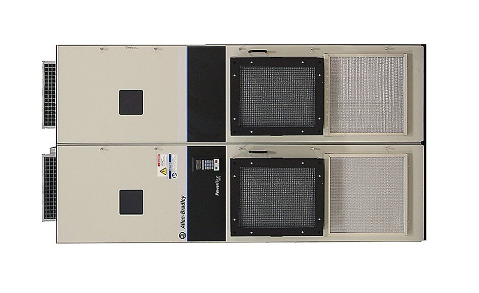
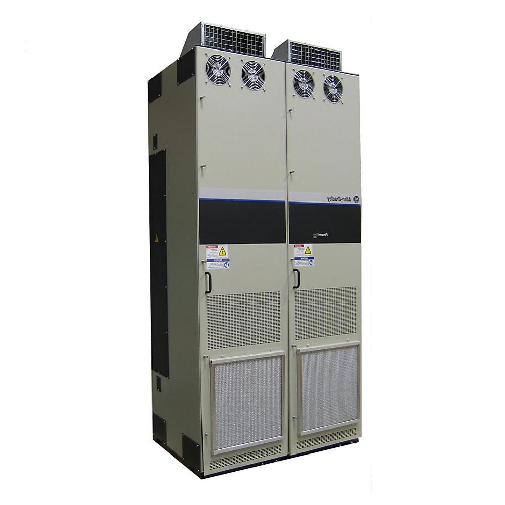
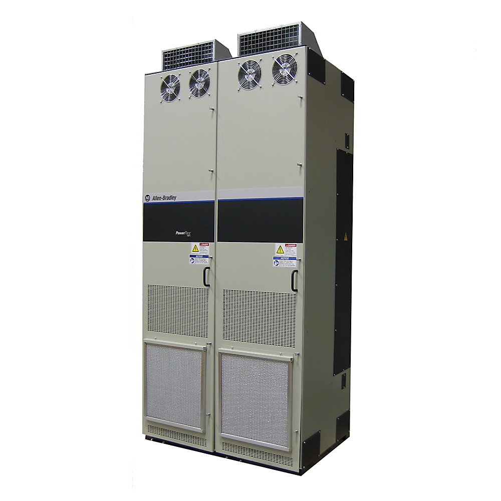
- 2,600–3,400 mm wide, 720 mm deep and 2,291 mm high
- 2531kg
- Xiamen, China
- New & In Stock
- T/T, PayPal, Western Union
- 1 Year
- 1-3 Working Days
- DHL, UPS, TNT, FedEx and EMS.
- 24-Hour Service
- COO
- 1
Our advantage

Global Logistics
We have a 10-year logistics and express cooperation agreement, so our products can be shipped to any place in the world.

Brand new and original
Our products are imported in bulk from the place of origin. Because of the cooperative relationship, our products are all original and 100% new.

24-hour service
We provide 7*24 hours service to our customers. We will be there whenever you need us.

Price advantage
All our products are priced very favorably because we have our own warehouse and supply.
| Company Information | |||
| [email protected] | |||
| Mobile | +8615980777398 | ||
| +8615980777398 | |||
| 15980777398 |
20J1F3F1K4LNDNNNNN — Detailed Product Information, Technical Specifications, Applications, Advantages and Related Models
1. Product Overview
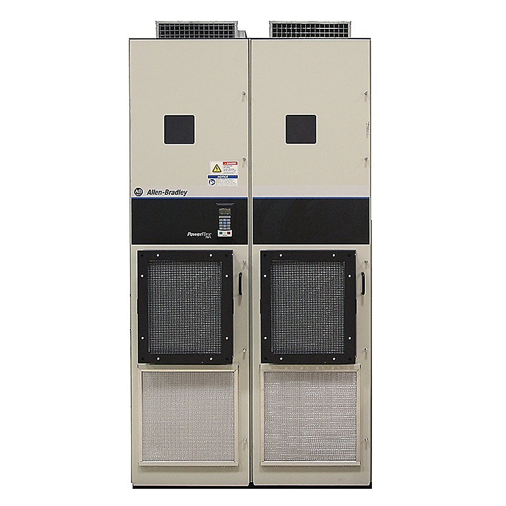
The 20J1F3F1K4LNDNNNNN is a high-power PowerFlex 750 Bus Supply designed for large industrial drive systems that require a centralized DC-bus power architecture.
This model belongs to the 20J1 product configuration and is part of the air-cooled 750 Bus Supply range. It is intended for large industrial installations rather than small standalone motor-drive applications.
The model is particularly suitable for systems in which several inverter sections share a common DC bus. This type of architecture is useful when a machine contains multiple motors, synchronized axes, high-power regenerative loads, or demanding acceleration and deceleration cycles.
The F1K4 rating identifies a high-power configuration in the approximately 1.4 MW class. For a 690 V-class system, this represents a very substantial industrial power level and requires appropriately sized upstream transformers, switchgear, protection equipment, cabling, busbars, ventilation and grounding infrastructure.
The LND portion of the catalog number identifies a particular configuration within the product’s overall catalog-number structure. Because the complete catalog number contains configuration characters, the exact electrical and mechanical options should always be matched against the nameplate when replacing an existing unit.
2. Basic Product Information
| Item | Specification |
|---|---|
| Model | 20J1F3F1K4LNDNNNNN |
| Brand | Allen-Bradley |
| Product Family | PowerFlex 750 Bus Supplies |
| Product Series | 20J1 |
| Product Type | Air-Cooled 750 Bus Supply |
| Main Function | High-power DC-bus power supply |
| System Architecture | Common DC-bus / regenerative drive system |
| Cooling | Air cooled |
| Voltage Class | 690 V-class configuration |
| Rated Power Class | Approximately 1,456 kW |
| Application Class | High-power industrial |
| Installation | Floor-standing industrial equipment |
| Enclosure Class | IP21 / NEMA Type 1 class configuration |
| Regenerative Architecture | Yes |
| Common DC Bus | Yes |
| Typical Application | Large multi-drive machinery |
| Frame | Large-frame configuration |
| Approx. Weight | Approximately 2,500 kg class |
| Approx. Dimensions | Approximately 2,600–3,400 W × 720 D × 2,291 H mm, configuration dependent |
3. Product Series and Classification
The 20J1F3F1K4LNDNNNNN belongs to the:
PowerFlex 750 Bus Supply Series
The product is designed as a high-power bus-supply component rather than as a conventional small standalone variable-frequency drive.
The main purpose is to provide a controlled DC bus to connected inverter sections.
A simplified system can be represented as:
AC Power → 20J1 Bus Supply → Common DC Bus → Inverter Sections → Motors
This architecture becomes particularly useful when a machine contains several motors that operate together.
For example, a large production line might have a main motor, several auxiliary motors, tension motors, take-up motors and positioning motors. Instead of treating every drive as a completely independent power system, the common DC-bus structure provides a centralized electrical power source.
4. Detailed Technical Specifications
| Parameter | Specification |
|---|---|
| Model | 20J1F3F1K4LNDNNNNN |
| Brand | Allen-Bradley |
| Product Family | PowerFlex 750 Bus Supplies |
| Series | 20J1 |
| Product Type | Air-Cooled 750 Bus Supply |
| Input System | Three-phase AC |
| Voltage Class | 690 V AC class |
| Power Rating | Approx. 1,456 kW |
| Power Class | Approx. 1.46 MW |
| Current Class | Approx. 1,450 A class |
| Frequency | 50/60 Hz system dependent |
| DC-Bus Output | Yes |
| Common-Bus Operation | Yes |
| Regenerative Operation | Yes |
| Cooling Method | Air cooled |
| Enclosure | IP21 / NEMA Type 1 class |
| Installation | Floor-standing |
| Control Architecture | PowerFlex 750-class control architecture |
| Main Application | High-power industrial drive systems |
| Approx. Width | 2,600–3,400 mm |
| Approx. Depth | 720 mm |
| Approx. Height | 2,291 mm |
| Approx. Weight | 2,531 kg class |
| Weight Unit | kg |
| Mechanical Construction | Large industrial cabinet/bay |
| Service Requirement | Industrial maintenance access |
| Typical Environment | Industrial electrical room |
| System Type | Centralized high-power drive system |
Note: The dimensions and weight are approximate because large bus-supply systems can be configured with different cabinet arrangements, wiring bays and optional equipment. The actual shipping dimensions and weight should be taken from the final mechanical configuration.
5. Electrical Characteristics
The 20J1F3F1K4LNDNNNNN is intended for a high-voltage industrial electrical system.
Its approximately 1,456 kW rating places it in the megawatt-class category.
At this power level, the incoming electrical infrastructure is an important part of the overall installation.
The power supply feeding the unit must be capable of supporting the required continuous and transient load.
The upstream transformer, switchgear, protection devices and conductors must also be selected according to the complete electrical system design.
The high-voltage architecture is particularly useful for large industrial machinery because higher system voltage allows high power to be transmitted at lower current than would be required at a much lower voltage.
6. Common DC-Bus Architecture
The central feature of this type of product is the common DC bus.
A conventional motor-drive system can be arranged as:
AC Supply → Individual Drive → Motor
A common-bus system instead uses:
AC Supply → Bus Supply → DC Bus → Multiple Drive Inverters → Multiple Motors
This architecture can provide several benefits.
Multiple inverter sections can receive their power from a common source.
The electrical system can be centralized.
Regenerative energy from one drive section can potentially be used by another connected section.
The system can also be designed around coordinated control of several motor axes.
This makes the product especially relevant to large machines rather than simple single-motor installations.
7. Regenerative Operation
One of the most important characteristics of a regenerative bus-supply system is its ability to deal with power flowing in both directions.
A conventional motor normally consumes electrical energy during acceleration and operation.
During deceleration, however, the motor can become a generator.
This can produce significant electrical energy, particularly when the machine has:
- Large rotating inertia
- High motor power
- Frequent braking
- Rapid speed changes
- Vertical movement
- Long conveyor sections
- Heavy lifting loads
Instead of simply dissipating this energy as heat, a regenerative system can manage the returned electrical energy through the DC-bus and AC-side power-conversion system.
This becomes increasingly important as the machine power increases.
8. Product Advantages
8.1 High-Power Capability
The approximately 1.46 MW rating makes this model suitable for very large industrial machines.
It is designed for applications where the electrical load is far beyond the normal range of compact variable-frequency drives.
This makes it suitable for heavy machinery, large processing equipment and multi-motor systems.
8.2 Centralized Power Conversion
The bus-supply concept allows the main AC-to-DC power conversion to be centralized.
Multiple drive sections can then be connected to the common DC bus.
This can produce a cleaner electrical architecture for large machinery.
8.3 Common DC-Bus Energy Sharing
A common DC bus allows energy to move between connected drive sections.
For example, if one motor is accelerating while another motor is decelerating, the electrical energy produced by the regenerative motor can potentially be used by another part of the system.
The exact energy flow depends on the system configuration and operating conditions.
8.4 Regenerative Energy Management
Regeneration is especially useful in high-inertia applications.
The system can be used where repeated braking would otherwise result in large amounts of heat being generated by braking resistors.
This is one of the key reasons a regenerative bus-supply architecture can be attractive for high-power machinery.
8.5 Suitable for Multi-Motor Machines
The product is well suited to machines with several coordinated drive axes.
Typical examples include:
- Large conveyors
- Cranes
- Hoists
- Mining machinery
- Rolling equipment
- Material-handling equipment
- Large process machinery
- Test systems
- High-power production lines
8.6 High-Voltage Industrial Design
The 690 V class is appropriate for large industrial electrical systems.
The higher voltage level helps reduce current for a given power requirement compared with lower-voltage systems.
This can influence conductor size, busbar design and overall electrical distribution.
9. Typical Applications
| Application | Description |
|---|---|
| Large conveyors | Multiple motors operating together on one production or material-handling system |
| Mining machinery | High-power motors for conveyors, processing and material movement |
| Cranes | Lifting, lowering and horizontal movement with frequent regeneration |
| Hoists | High-power vertical movement and braking |
| Steel processing | Large synchronized motors and process lines |
| Rolling equipment | High-power coordinated motor control |
| Material handling | Multiple motors with changing load conditions |
| Large test stands | Repeated acceleration and deceleration |
| Process machinery | Continuous high-power operation |
| Large production lines | Multiple coordinated motor axes |
| Heavy industrial fans | High-power variable-speed applications |
| Large pumps | High-power process systems where variable speed is required |
10. Application: Large Conveyor Systems
A large conveyor can contain multiple motors distributed along the conveyor.
The motors may not always consume energy at exactly the same time.
During acceleration, several motors may require significant power.
During deceleration, some motors can return energy to the DC bus.
With a common DC-bus architecture, the electrical system can be designed around this interaction.
This is particularly useful when the conveyor is long, heavily loaded and subject to frequent speed changes.
11. Application: Crane and Hoisting Systems
Cranes and hoists are another important application.
When lifting a load, the motor generally operates in a motoring condition.
When lowering the load, the motor can enter regeneration.
During rapid stopping, additional regenerative energy can also be generated.
The regenerative bus-supply architecture is therefore well suited to applications in which power can repeatedly move between motoring and generating conditions.
12. Application: Multi-Axis Production Equipment
Large production machines frequently contain multiple motor axes.
For example:
- Main process motor
- Feed motor
- Take-up motor
- Tension motor
- Positioning motor
- Auxiliary motor
- Cooling system motor
- Pump motor
A common DC bus provides a centralized electrical architecture for these drive sections.
This can make system integration more structured, especially when the individual motors have different acceleration, deceleration and load profiles.
13. Application: Mining and Heavy Industry
Mining equipment often operates with extremely large mechanical loads.
Long conveyors, crushers, material handling equipment and processing systems can require very high motor power.
The 20J1 family is appropriate to this class of electrical infrastructure because it can form the power-conversion center of a multi-drive system.
The final system design must still account for environmental conditions such as dust, ambient temperature, altitude and ventilation.
14. Dimensions and Weight
The physical size of this model is a major consideration.
| Mechanical Parameter | Approximate Value |
|---|---|
| Model | 20J1F3F1K4LNDNNNNN |
| Installation | Floor-standing |
| Width | Approx. 2,600–3,400 mm |
| Depth | Approx. 720 mm |
| Height | Approx. 2,291 mm |
| Approx. Weight | Approx. 2,531 kg |
| Weight | 2,531 kg class |
| Cooling | Air cooled |
| Cabinet Type | Large industrial cabinet/bay |
| Floor Loading | Must be verified |
| Transportation | Heavy-duty handling equipment |
| Service Access | Required around cabinet |
| Wiring Bay Effect | May increase overall dimensions and weight |
The 2,531 kg figure should be treated as an approximate equipment-class value rather than a guaranteed shipping weight.
The final weight can be higher depending on wiring bays, cabinet construction and installed options.
15. Installation Requirements
Because the product is approximately 2.5 tonnes, mechanical installation is an important part of the project.
Before installation, the following should be considered:
| Installation Item | Requirement |
|---|---|
| Floor capacity | Must support the installed equipment |
| Cabinet access | Adequate front/service access |
| Transportation | Suitable route for large equipment |
| Lifting | Appropriate lifting equipment |
| Ventilation | Adequate airflow |
| Ambient temperature | Must remain within applicable limits |
| Dust | Must be controlled appropriately |
| Humidity | Must be suitable for the equipment |
| Cable routing | High-power cable arrangement required |
| Grounding | Proper industrial grounding system |
| Protection | Upstream protection must be coordinated |
| Maintenance | Adequate service clearance |
16. Five Related Models in the Same Series
The following models are closely related to the 20J1 bus-supply configuration and are useful for comparing different power levels.
The dimensions and weights for the larger configurations are shown as approximate because the final cabinet arrangement can vary.
| Model | Product Type | Voltage Class | Approx. Power Rating | Cooling | DC Bus | Regenerative Architecture | Approx. Dimensions | Approx. Weight |
|---|---|---|---|---|---|---|---|---|
| 20J1F3F1K1LNDNNNNN | Air-Cooled 750 Bus Supply | 690 V class | Approx. 1,180 kW | Air cooled | Yes | Yes | Large-frame cabinet | Approx. 2,100 kg |
| 20J1F3F1K4LNDNNNNN | Air-Cooled 750 Bus Supply | 690 V class | Approx. 1,456 kW | Air cooled | Yes | Yes | Approx. 2600–3400 × 720 × 2291 mm | Approx. 2,531 kg |
| 20J1F3F1K8LNDNNNNN | Air-Cooled 750 Bus Supply | 690 V class | Approx. 1,914 kW | Air cooled | Yes | Yes | Large-frame cabinet | Approx. 2,500 kg class |
| 20J1F3F2K3LNDNNNNN | Air-Cooled 750 Bus Supply | 690 V class | Approx. 2,379 kW | Air cooled | Yes | Yes | Large multi-bay cabinet | Approx. 3,000 kg class |
| 20J1F3F3K6LNDNNNNN | Air-Cooled 750 Bus Supply | 690 V class | Approx. 3,781 kW | Air cooled | Yes | Yes | Very large multi-bay cabinet | Approx. 5,000+ kg class |
These are related configurations rather than guaranteed direct replacements.
A higher-rated model can have a different frame, cabinet arrangement, cooling requirement, busbar structure and installation footprint.
17. Comparison of Related 20J1 Models
| Parameter | 20J1F3F1K1LNDNNNNN | 20J1F3F1K4LNDNNNNN | 20J1F3F1K8LNDNNNNN | 20J1F3F2K3LNDNNNNN | 20J1F3F3K6LNDNNNNN |
|---|---|---|---|---|---|
| Voltage Class | 690 V | 690 V | 690 V | 690 V | 690 V |
| Power Class | ~1,180 kW | ~1,456 kW | ~1,914 kW | ~2,379 kW | ~3,781 kW |
| Product Type | Bus Supply | Bus Supply | Bus Supply | Bus Supply | Bus Supply |
| Cooling | Air cooled | Air cooled | Air cooled | Air cooled | Air cooled |
| Common DC Bus | Yes | Yes | Yes | Yes | Yes |
| Regeneration | Yes | Yes | Yes | Yes | Yes |
| Installation | Floor-standing | Floor-standing | Floor-standing | Floor-standing | Floor-standing |
| Approx. Weight | ~2,100 kg | ~2,531 kg | ~2,500 kg class | ~3,000 kg class | ~5,000+ kg class |
| Approx. Size | Large | Large | Large | Very large | Extremely large |
| Application | High-power machinery | High-power machinery | Higher-power machinery | Heavy industrial | Multi-megawatt systems |
18. Five Related Models from the Broader Product Range
For users who are comparing alternatives, the following models represent other industrial drive configurations within the same overall brand portfolio.
These should not be treated as direct replacements for the 20J1F3F1K4LNDNNNNN.
They are individual-drive products and operate at substantially different power levels.
| Model | Product Family | Product Type | Voltage Class | Approx. Power Class | Cooling | Approx. Dimensions | Approx. Weight |
|---|---|---|---|---|---|---|---|
| 20F1AGF012JN0NNNNN | PowerFlex 753 | AC Drive | 690 V class | Approx. 7.5 kW | Air cooled | Approx. 665 × 308 × 346 mm | Approx. 38.6 kg |
| 20F1AGF020JN0NNNNN | PowerFlex 753 | AC Drive | 690 V class | Approx. 15 kW | Air cooled | Approx. 665 × 308 × 346 mm | Approx. 38.6 kg |
| 20G2ANF050JA0NNNNN | PowerFlex 755TS | AC Drive | 690 V class | Approx. 45–50 kW | Air cooled | Configuration dependent | Configuration dependent |
| 20G2ANF119JA0NNNNN | PowerFlex 755TS | AC Drive | 690 V class | Approx. 110–120 kW | Air cooled | Configuration dependent | Configuration dependent |
| 20G2ANF212JA0NNNNN | PowerFlex 755TS | AC Drive | 690 V class | Approx. 200–220 kW | Air cooled | Configuration dependent | Configuration dependent |
For these smaller drive configurations, the physical dimensions and weight can vary considerably with frame and option configuration.
Therefore, the table is intended as a product-family comparison rather than a mechanical replacement guide.
19. 20J1 vs. Individual AC Drives
| Feature | 20J1F3F1K4LNDNNNNN | PowerFlex 753 Class | PowerFlex 755TS Class |
|---|---|---|---|
| Main Function | Bus supply | Individual motor drive | Individual high-performance motor drive |
| Power Level | ~1.46 MW | Low/medium power | Medium/high power |
| Common DC Bus | Yes | Application dependent | Application dependent |
| Regenerative Architecture | Core function | Configuration dependent | Configuration dependent |
| Number of Motors | Multiple drive sections | Usually individual motor | Usually individual motor |
| Installation | Large floor-standing system | Cabinet/panel | Cabinet/panel |
| Weight | ~2,531 kg class | Tens of kg class at smaller ratings | Frame dependent |
| Main Application | Large multi-drive machine | General motor control | Advanced motor/process control |
| Electrical Architecture | Centralized | Distributed | Distributed or system-based |
20. Main Advantages for Industrial Users
The product’s advantages become most obvious when the application is large enough to justify a centralized power architecture.
Centralized Power
The incoming electrical power is converted into a common DC-bus supply that can serve multiple inverter sections.
Regeneration
The architecture can handle energy returned from regenerative motor operation.
Multi-Drive Integration
Several drive sections can operate from a shared electrical power system.
High Power
The approximately 1.46 MW rating is suitable for very large industrial machinery.
Energy Sharing
A common DC bus can permit energy exchange between connected drive sections.
Large-System Flexibility
The 20J1 family includes multiple power levels, allowing engineers to select different ratings according to the application.
21. Engineering Considerations
At this power level, the product should be considered as one component within a complete engineered system.
The following areas deserve particular attention.
Transformer Selection
The upstream transformer must have sufficient capacity for the required operating power and transient conditions.
Switchgear
The incoming switchgear must be correctly rated for voltage, current and available fault current.
Protection
The protection system must be coordinated with the bus supply and connected drive equipment.
Cable and Busbar Design
The current level requires careful consideration of conductor cross-section, temperature rise, mechanical support and routing.
Grounding
A suitable industrial grounding system is essential.
Cooling
Airflow and heat removal need to be designed for the actual installation environment.
Floor Loading
The approximately 2.5-tonne equipment weight makes floor loading a significant mechanical consideration.
22. Product Selection Checklist
When selecting or replacing the 20J1F3F1K4LNDNNNNN, the following checklist can be used.
| Selection Item | Check |
|---|---|
| Model number | 20J1F3F1K4LNDNNNNN |
| Product family | PowerFlex 750 Bus Supply |
| Voltage | 690 V class |
| Power | Approximately 1,456 kW |
| Current | Approximately 1,450 A class |
| Cooling | Air cooled |
| Regeneration | Required |
| DC bus | Required |
| Enclosure | IP21 / NEMA Type 1 class |
| Cabinet space | Approximately 2.6–3.4 m width class |
| Depth | Approximately 720 mm |
| Height | Approximately 2.291 m |
| Weight | Approximately 2,531 kg |
| Wiring configuration | Must match original system |
| Optional equipment | Must be checked |
| Control system | Must be compatible |
| Motor inverters | Must match DC-bus requirements |
| Installation environment | Must be suitable |
| Service clearance | Must be sufficient |
23. Recommended Use Cases
The 20J1F3F1K4LNDNNNNN is particularly relevant when a project has one or more of the following characteristics:
- Total installed drive power in the megawatt range
- Multiple motors operating from one machine
- Frequent acceleration and deceleration
- Significant regenerative energy
- High-inertia loads
- Common DC-bus architecture
- 690 V-class industrial electrical distribution
- Large conveyor systems
- Mining machinery
- Cranes and hoists
- Heavy material-handling equipment
- Large process machinery
- Multi-axis production equipment
24. Product Advantages at a Glance
| Advantage | Description |
|---|---|
| High Power | Approximately 1.46 MW class |
| Regeneration | Designed for systems with regenerative power flow |
| Common DC Bus | Multiple inverter sections can share a DC bus |
| Energy Sharing | Allows power exchange between connected drive sections |
| Industrial Voltage | Suitable for 690 V-class systems |
| Large-System Integration | Designed for complex multi-drive systems |
| Air Cooling | Suitable for large industrial installations with appropriate ventilation |
| Scalable Family | Related configurations cover different power levels |
| Heavy-Duty Application | Appropriate for demanding industrial machinery |
| Centralized Architecture | Main power conversion can be centralized |
25. Technical Summary
| Category | Specification |
|---|---|
| Model | 20J1F3F1K4LNDNNNNN |
| Brand | Allen-Bradley |
| Series | PowerFlex 750 Bus Supplies |
| Product Type | Air-Cooled 750 Bus Supply |
| Configuration | 20J1 |
| Voltage Class | 690 V |
| Power Rating | Approx. 1,456 kW |
| Power Level | Approx. 1.46 MW |
| Current Class | Approx. 1,450 A |
| Input | Three-phase AC |
| DC Bus | Yes |
| Regenerative Operation | Yes |
| Cooling | Air cooled |
| Enclosure | IP21 / NEMA Type 1 class |
| Installation | Floor-standing |
| Approx. Width | 2,600–3,400 mm |
| Approx. Depth | 720 mm |
| Approx. Height | 2,291 mm |
| Approx. Weight | 2,531 kg |
| Weight Unit | kg |
| Main Application | Large multi-drive industrial systems |
| Typical Industries | Mining, metals, material handling, heavy processing |
| Main Advantage | Centralized high-power regenerative DC-bus architecture |
26. Final Product Description
The 20J1F3F1K4LNDNNNNN is a high-power PowerFlex 750 Bus Supply intended for large industrial drive systems.
With an approximately 1,456 kW power rating and a 690 V-class electrical configuration, it belongs to a completely different application category from compact variable-frequency drives.
Its main purpose is to provide a centralized electrical power source for a common DC-bus drive system.
The architecture is particularly useful when several motors operate as part of one large machine. Instead of every motor drive requiring an independent AC power-conversion section, multiple inverter sections can be supplied from a common DC bus.
Another important feature is regenerative operation. Large industrial machines often generate substantial electrical energy when motors decelerate, loads are lowered or high-inertia equipment is stopped. A regenerative bus-supply architecture provides a way to manage this returned energy through the electrical system.
The product is therefore particularly relevant to large conveyors, mining machinery, cranes, hoists, heavy material-handling systems, rolling equipment, test stands and other multi-motor industrial machinery.
From a mechanical perspective, this is also a very large piece of equipment. A typical configuration is approximately 2,600–3,400 mm wide, 720 mm deep and 2,291 mm high, with a weight in the region of 2,531 kg. Actual dimensions and weight can change depending on the final cabinet arrangement and installed options.
For replacement purposes, the complete catalog number 20J1F3F1K4LNDNNNNN should be matched carefully. The power rating alone is not sufficient to establish interchangeability because cabinet arrangement, voltage, cooling, enclosure, bus configuration and additional options can affect the final system.
Overall, this model is best viewed as the central high-power electrical supply section of a large industrial multi-drive system, rather than as a conventional single-motor frequency inverter.