

ProductPRODUCT
Featured products
Contact Us
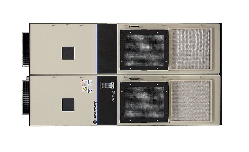
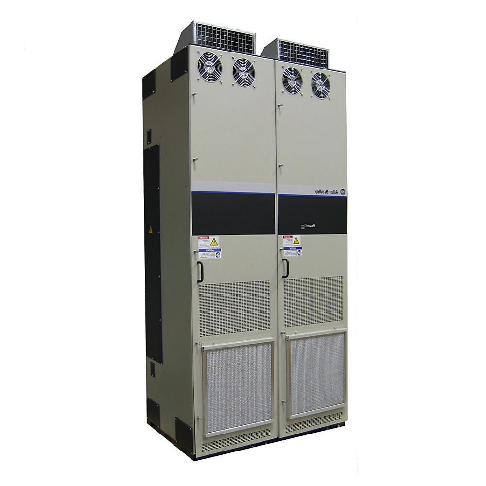
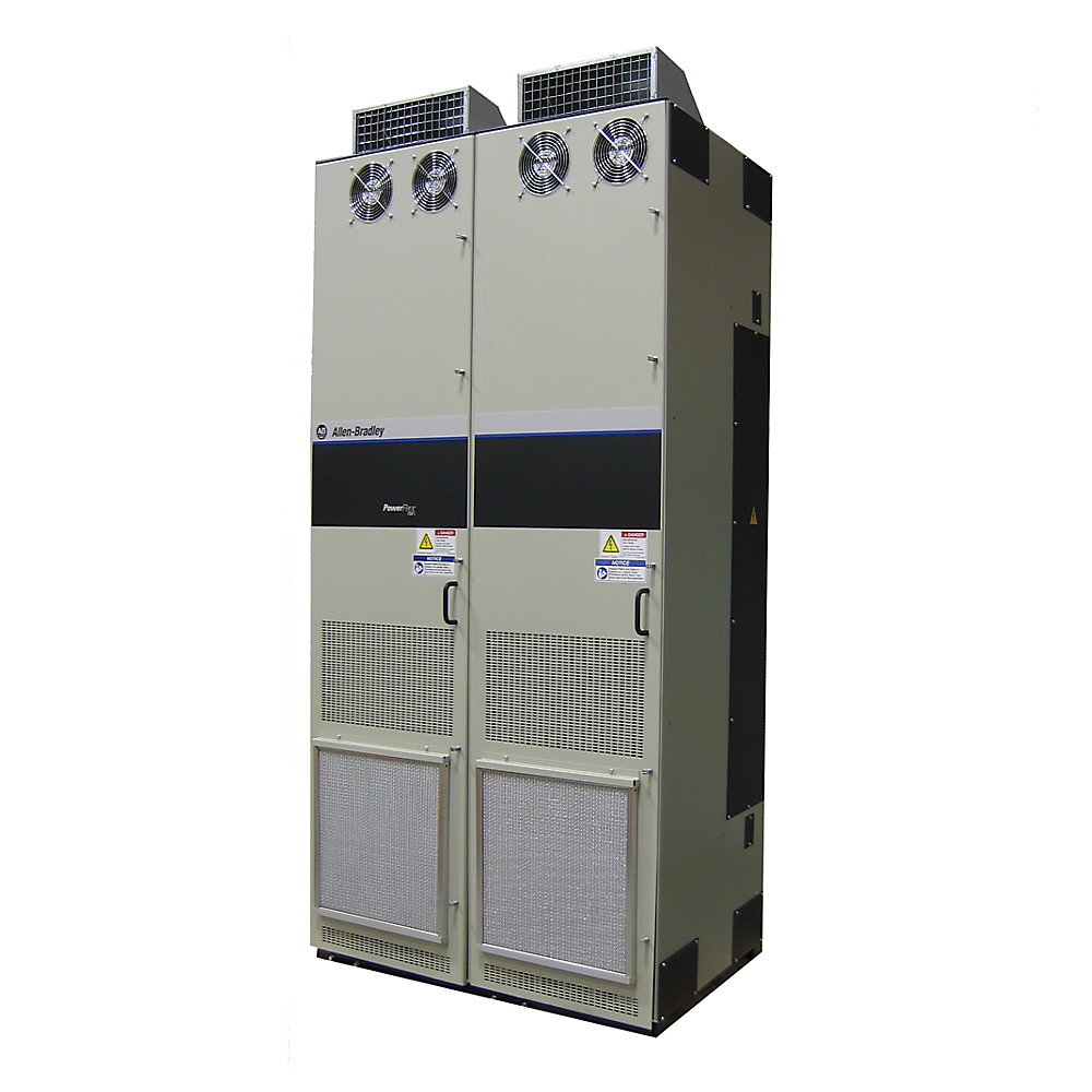
- Allen Bradley
- 20J1F3C650LNANNNNN
- PowerFlex AC Drive
- USA
- 1,100–1,600 mm high × 600–900 mm wide × 550–900 mm deep
- 250kg
- Xiamen, China
- New & In Stock
- T/T, PayPal, Western Union
- 1 Year
- 1-3 Working Days
- DHL, UPS, TNT, FedEx and EMS.
- 24-Hour Service
- COO
- 3
Our advantage

Global Logistics
We have a 10-year logistics and express cooperation agreement, so our products can be shipped to any place in the world.

Brand new and original
Our products are imported in bulk from the place of origin. Because of the cooperative relationship, our products are all original and 100% new.

24-hour service
We provide 7*24 hours service to our customers. We will be there whenever you need us.

Price advantage
All our products are priced very favorably because we have our own warehouse and supply.
| Company Information | |||
| [email protected] | |||
| Mobile | +8615980777398 | ||
| +8615980777398 | |||
| 15980777398 |
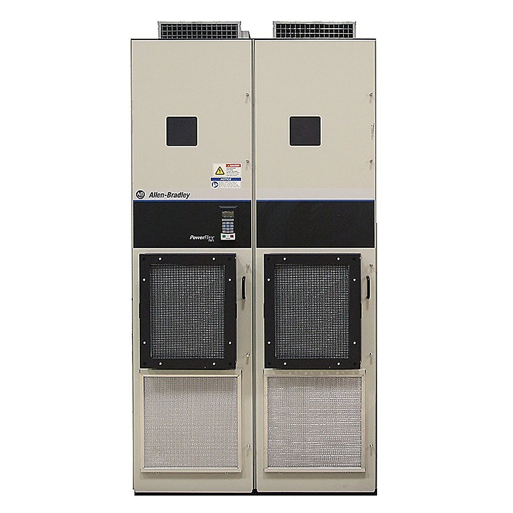
Allen-Bradley 20J1F3C650LNANNNNN PowerFlex 750 Bus Supply
1. Product Overview
The Allen-Bradley 20J1F3C650LNANNNNN is a high-power PowerFlex 750 Bus Supply configured in an air-cooled architecture.
It is designed for industrial drive systems that require a centralized DC-bus power source for multiple connected drive sections. Instead of functioning as a conventional standalone AC motor drive, the unit serves as a common power-conversion section within a larger multi-drive system.
The C650 configuration belongs to the larger-capacity portion of the 20J1F3 air-cooled bus-supply family and is intended for demanding industrial applications where substantial electrical power must be supplied to a common DC bus.
The PowerFlex 750 Bus Supply family is specifically associated with common-bus drive architectures, allowing multiple compatible inverter sections to share a centralized DC power system. The product family includes multiple frame and capacity configurations for different machine power requirements.
The 20J1F3C650LNANNNNN is therefore best considered a major power-conversion component in a large industrial automation system rather than a simple individual motor controller.
2. Basic Product Information
| Parameter | Specification |
|---|---|
| Brand | Allen-Bradley |
| Model | 20J1F3C650LNANNNNN |
| Product Family | PowerFlex 750 Bus Supplies |
| Product Type | Air-Cooled 750 Bus Supply |
| Product Configuration | 20J1F3C650 |
| Configuration Class | C650 |
| Cooling Method | Air Cooled |
| System Architecture | Common DC Bus |
| Primary Function | Centralized DC-bus power supply |
| Application Type | High-power multi-drive industrial systems |
| Mounting Concept | Industrial cabinet / floor-mounted installation |
| Drive System | PowerFlex 750-class architecture |
| Installation Environment | Industrial |
| Main Application | Multi-motor and coordinated drive systems |
| Power Class | High Power |
| Service Concept | Industrial engineered power-conversion equipment |
| Mechanical Construction | High-power enclosed drive-system assembly |
| Typical System Position | Upstream DC-bus power source |
| Output Architecture | Shared DC bus |
| Thermal Management | Forced-air cooling |
The 20J1F3 product family is identified as the PowerFlex 750 Bus Supplies family, and the C650 configuration is one of the higher-capacity configurations within the air-cooled group.
3. Product Series
PowerFlex 750 Bus Supplies
The 20J1F3C650LNANNNNN belongs to the PowerFlex 750 Bus Supplies series.
This series was developed for applications in which multiple drive sections can be connected to a common DC-bus infrastructure.
The basic concept is different from using independent AC drives throughout a machine. A dedicated bus supply establishes the DC power source, while individual inverter sections can then control their respective motors.
This arrangement is particularly useful for large machines containing multiple motors that operate as part of one production process.
The PowerFlex common-bus concept has been used for applications involving coordinated machinery, multi-drive systems, regenerative energy management, material handling, and other high-power industrial processes.
4. Product Type
The product can be described as:
Air-Cooled High-Power Common DC Bus Supply
The main energy path can be simplified as:
AC Input → Bus Supply → DC Bus → Drive Inverters → Motors
This architecture allows the bus supply to provide centralized DC power to multiple downstream inverter sections.
The individual inverter sections can then perform motor-speed and torque control according to the requirements of the machine.
This makes the 20J1F3C650LNANNNNN especially useful where a machine has multiple motors rather than one isolated motor.
5. Main Technical Parameters
The C650 configuration is associated with the following published power and current classes for the 20J1F3 air-cooled bus-supply configuration:
| Parameter | Specification |
|---|---|
| Model | 20J1F3C650LNANNNNN |
| Brand | Allen-Bradley |
| Series | PowerFlex 750 Bus Supplies |
| Product Type | Air-Cooled 750 Bus Supply |
| Configuration | C650 |
| Cooling | Air Cooled |
| Architecture | Common DC Bus |
| Light Duty Rating | Approximately 467 kW / 805 A |
| Normal Duty Rating | Approximately 405 kW / 698 A |
| Heavy Duty Rating | Approximately 336 kW / 579 A |
| Output Architecture | Common DC bus |
| Installation | Industrial cabinet / floor-mounted system |
| Typical Application | High-power multi-drive system |
| Input System | Industrial AC supply, configuration dependent |
| Thermal Management | Forced air |
| Enclosure | Configuration dependent |
| Approximate Dimensions | 1,100–1,600 mm H × 600–900 mm W × 550–900 mm D |
| Approximate Weight | 150–250 kg |
| Dimension Status | Engineering planning estimate |
| Weight Status | Engineering planning estimate |
The C650 ratings above should be understood as configuration-level ratings rather than assuming that every possible suffix option has identical operating characteristics.
The PowerFlex 750 technical documentation also shows the C650 designation in the high-power drive range and associates C650-class equipment with substantially larger physical installation requirements than lower-power configurations.
The dimensions and weight in this table are planning ranges, not certified mechanical drawing values. For cabinet fabrication, lifting calculations, transportation, and final installation, the actual configured unit documentation should be used.
6. Power Rating Details
The C650 configuration is designed for high-power industrial applications.
Its approximate operating classes can be summarized as follows:
| Duty Class | Approx. Power | Approx. Current | Typical Duty Concept |
|---|---|---|---|
| Light Duty | 467 kW | 805 A | Higher continuous power where duty permits |
| Normal Duty | 405 kW | 698 A | General heavy industrial operation |
| Heavy Duty | 336 kW | 579 A | Higher overload-demand applications |
These ratings illustrate why the C650 configuration belongs to the high-power portion of the PowerFlex 750 architecture.
The actual selection of light-duty, normal-duty, or heavy-duty operation should be based on the complete machine load profile, acceleration requirements, overload requirements, ambient conditions, and the operating cycle.
7. What the C650 Configuration Means in Practice
The C650 designation is important because it places the product in a substantially higher power class than smaller configurations such as C302 or C367.
For a machine builder, this means that the product is generally considered when the total power requirement of a multi-drive system has moved beyond the practical range of smaller bus-supply configurations.
Typical examples include large conveyors, heavy material-handling equipment, metal-processing machinery, large process lines, mining equipment, and other machines with several high-power motors.
The C650 configuration can therefore be regarded as a system-level power component rather than an individual motor-control component.
8. Product Introduction
The 20J1F3C650LNANNNNN provides a centralized power source for a common DC-bus drive system.
In a conventional drive arrangement, every individual AC drive normally contains its own input power-conversion section.
A common-bus system takes a different approach.
The incoming AC power is processed by the bus supply, and the resulting DC power is distributed to multiple compatible drive inverter sections.
Each inverter can then control its connected motor while sharing the common electrical infrastructure.
This arrangement is particularly attractive when many motors belong to the same machine.
For example, a large processing line may contain several motors controlling different rollers, conveyors, pumps, tension sections, or material-handling mechanisms.
Instead of designing each drive section as a completely independent electrical island, the machine can be organized around a common DC bus.
9. Common DC Bus Architecture
The common DC-bus architecture is one of the defining characteristics of this product family.
A simplified arrangement is:
Main AC Supply
↓
Input Protection
↓
20J1F3C650LNANNNNN
↓
Common DC Bus
↓
Inverter Section 1 → Motor 1
Inverter Section 2 → Motor 2
Inverter Section 3 → Motor 3
Inverter Section 4 → Motor 4
Additional Drive Sections
↓
Complete Machine
This arrangement allows the electrical system to be designed around the machine as a whole.
The bus supply becomes the centralized DC power source, while individual drive sections remain responsible for controlling individual motors.
10. Main Applications
10.1 Large Conveyor Systems
Large conveyor systems are one of the most suitable application categories for high-power common-bus architectures.
A long conveyor can contain several drive motors positioned along the mechanical system.
These motors may need coordinated acceleration, speed regulation, torque control, and stopping.
The 20J1F3C650LNANNNNN can serve as the central bus-supply component for such a multi-drive architecture.
Typical applications include bulk-material conveyors, mining conveyors, warehouse transport systems, large production conveyors, and heavy industrial material-transfer systems.
10.2 Mining Equipment
Mining equipment often requires substantial motor power.
Applications may include:
- Ore conveyors
- Crushers
- Material handling systems
- Large fans
- Pumps
- Hoisting systems
- Processing equipment
- Heavy-duty transport systems
The high-power C650 configuration can be considered when several large drive sections must operate together.
10.3 Metal Processing
Metal-processing machinery frequently contains several high-power motors.
Examples include:
- Rolling systems
- Strip-processing lines
- Coil handling
- Payoff systems
- Take-up systems
- Cutting equipment
- Positioning systems
- Material-transfer equipment
The common DC-bus arrangement can provide a centralized electrical infrastructure for coordinated motor control.
10.4 Web Handling
Web-processing machinery is another important application area.
Examples include:
- Printing lines
- Coating lines
- Laminating lines
- Slitting machines
- Film processing
- Paper processing
- Foil processing
- Unwind systems
- Rewind systems
In these machines, multiple motors may operate at carefully coordinated speeds.
A common DC-bus architecture can be useful where the drive sections are part of one integrated production process.
10.5 Large Material-Handling Systems
Large material-handling machinery can contain numerous motor sections.
Examples include:
- Automated production lines
- Transfer systems
- Large conveyors
- Pallet-handling equipment
- Industrial logistics systems
- Heavy-duty lifting and transport machinery
The C650 bus supply provides a high-power platform for such systems.
10.6 Process Machinery
Large process machines may use multiple pumps, fans, conveyors, mixers, rollers, or mechanical actuators.
A common-bus system can centralize the primary power-conversion architecture while allowing each individual motor to retain independent control.
10.7 Heavy Industrial Machinery
The product can also be considered for large machines where several high-power motors operate simultaneously.
Typical examples include:
- Industrial processing equipment
- Large machine tools
- Heavy production machinery
- Continuous-process equipment
- Large ventilation systems
- High-capacity pumping systems
- Industrial test machinery
11. Product Advantages
11.1 Centralized DC Power Architecture
The most important advantage is centralized power conversion.
The bus supply provides the DC power infrastructure, while multiple inverter sections can use the common bus.
This can simplify the overall electrical architecture of a large multi-drive machine.
11.2 High Power Capability
The C650 configuration occupies a high-power position within the PowerFlex 750 Bus Supply family.
With approximately 467 kW light-duty, 405 kW normal-duty, and 336 kW heavy-duty ratings, it is intended for applications substantially larger than typical small industrial drives.
11.3 Multi-Motor Integration
A single bus supply can support a system containing multiple drive inverter sections.
This is useful when several motors form one integrated machine.
The machine designer can therefore separate the centralized power-conversion function from the individual motor-control functions.
11.4 Improved System Organization
A common-bus system can provide a more structured arrangement for large drive cabinets.
The bus supply, DC bus, inverter sections, protection devices, and control equipment can be organized into a coordinated system.
This can be especially useful for large machine builders and system integrators.
11.5 Suitable for Coordinated Motion
The architecture is particularly useful for machinery where multiple motors must operate together.
Examples include synchronized conveyors, rollers, unwind/rewind systems, processing lines, and material-handling systems.
11.6 Air-Cooled Construction
The air-cooled design provides a practical thermal-management approach for industrial installations where forced-air cooling is acceptable.
It does not require a dedicated liquid-cooling infrastructure.
Proper cabinet ventilation and airflow management remain essential.
11.7 Scalable Product Family
The 20J1F3 family contains different configurations, allowing system designers to select a bus supply appropriate to the total electrical requirements of the machine.
This makes it possible to use a consistent product architecture across different machine sizes.
11.8 High-Current Industrial Capability
The C650 configuration reaches approximately 805 A in its light-duty rating class.
This places the product in a current range appropriate for large industrial power systems.
High-current equipment of this class requires careful engineering of busbars, protective devices, cable systems, grounding, ventilation, and cabinet construction.
12. Mechanical Parameters
| Mechanical Parameter | Specification |
|---|---|
| Model | 20J1F3C650LNANNNNN |
| Product Type | High-Power Air-Cooled Bus Supply |
| Installation | Industrial cabinet / floor-mounted |
| Cooling | Forced Air |
| Approx. Height | 1,100–1,600 mm |
| Approx. Width | 600–900 mm |
| Approx. Depth | 550–900 mm |
| Approx. Weight | 150–250 kg |
| Cabinet Integration | Required |
| Ventilation | Required |
| Maintenance Clearance | Required |
| Lifting Equipment | May be required |
| Transportation | Industrial handling recommended |
| Mechanical Data | Planning estimate only |
The dimensions and weight should be treated as preliminary engineering values.
The actual mechanical envelope can vary with the complete configuration, enclosure arrangement, accessories, bus hardware, protective equipment, and installation method.
13. Electrical Installation Considerations
A C650-class bus supply should be treated as major industrial electrical equipment.
The incoming AC system must be correctly sized for the expected operating current.
Protection must be selected according to the actual configuration and applicable electrical requirements.
The DC bus distribution system must also be engineered for the expected current.
Busbars, cables, terminals, disconnect devices, protective equipment, grounding, and cabinet thermal performance all need to be considered as part of the complete installation.
The bus supply should not be selected solely by comparing the nominal motor horsepower.
The total connected load, simultaneous operating load, duty cycle, overload requirements, regenerative behavior, ambient temperature, altitude, and machine operating profile should all be considered.
14. Thermal Management
Because this is an air-cooled high-power unit, thermal management is a major design consideration.
The cabinet must provide sufficient airflow to remove heat generated by the power-conversion equipment.
The cooling system should prevent hot air from being recirculated into the equipment intake.
Filters, fans, air passages, and cabinet ventilation should be maintained regularly.
High ambient temperature can reduce available capacity and should therefore be included in the system design.
15. Environmental Considerations
The common-bus architecture is intended for industrial environments, but the actual installation must still satisfy the environmental requirements of the configured equipment.
Important factors include:
- Ambient temperature
- Altitude
- Humidity
- Dust
- Contamination
- Vibration
- Shock
- Ventilation
- Cabinet temperature
- Corrosive atmosphere
- Installation elevation
The common DC-bus technical guidance indicates that environmental conditions such as altitude, temperature, humidity, shock, and vibration must be considered when applying common-bus equipment.
16. Maintenance
Regular maintenance should include inspection of cooling fans, ventilation passages, electrical connections, bus connections, grounding connections, and signs of overheating.
Dust accumulation can reduce cooling efficiency.
Fan deterioration can also increase operating temperature and reduce equipment reliability.
The DC bus must always be treated as a potentially hazardous energy source.
Before maintenance, the system should be isolated according to the appropriate electrical safety procedure, and stored electrical energy must be verified to have been discharged before personnel access.
17. Five Recommended Models in the Same Series
The following models are useful comparison choices within the same general 20J1F3 air-cooled PowerFlex 750 Bus Supply family.
| Model | Product Type | Cooling | Configuration | Approx. Power Class | Approx. Current Class | Approx. Dimensions | Approx. Weight |
|---|---|---|---|---|---|---|---|
| 20J1F3C302LNANNNNN | 750 Bus Supply | Air Cooled | C302 | Lower | Approx. 300–400 A class | 900–1,300 × 450–700 × 450–700 mm | 100–160 kg |
| 20J1F3C367LNANNNNN | 750 Bus Supply | Air Cooled | C367 | Medium | Approx. 400–500 A class | 950–1,400 × 500–750 × 450–750 mm | 110–180 kg |
| 20J1F3C540LNANNNNN | 750 Bus Supply | Air Cooled | C540 | High | Approx. 500–700 A class | 1,000–1,500 × 500–800 × 500–800 mm | 130–210 kg |
| 20J1F3C770LNANNNNN | 750 Bus Supply | Air Cooled | C770 | Very High | Approx. 800–900 A class | 1,200–1,700 × 600–900 × 550–900 mm | 170–270 kg |
| 20J1F3C920LNANNNNN | 750 Bus Supply | Air Cooled | C920 | Extra High | Approx. 900–1,100 A class | 1,300–1,800 × 650–950 × 600–950 mm | 190–300 kg |
These are intended as related-model selection references, not exact substitution recommendations.
The 20J1F3 family contains a broad range of configurations, including C302, C540, C650, C770 and C920 classes, making it suitable for different levels of industrial drive-system capacity.
18. Same-Series Comparison Table
| Model | Light-Duty Class | Normal-Duty Class | Heavy-Duty Class | Cooling | Approx. Weight |
|---|---|---|---|---|---|
| 20J1F3C302LNANNNNN | Approx. 228 kW / 394 A | Approx. 188 kW / 324 A | Approx. 162 kW / 279 A | Air Cooled | 100–160 kg |
| 20J1F3C540LNANNNNN | Approx. 400–450 kW class | Approx. 350–400 kW class | Approx. 300–350 kW class | Air Cooled | 130–210 kg |
| 20J1F3C650LNANNNNN | 467 kW / 805 A | 405 kW / 698 A | 336 kW / 579 A | Air Cooled | 150–250 kg |
| 20J1F3C770LNANNNNN | Approx. 518 kW / 893 A | Approx. 479 kW / 826 A | Approx. 405 kW / 698 A | Air Cooled | 170–270 kg |
| 20J1F3C920LNANNNNN | Approx. 647 kW / 1116 A | Approx. 572 kW / 987 A | Approx. 479 kW / 826 A | Air Cooled | 190–300 kg |
The C302, C770, and C920 ratings shown above correspond to the respective configuration classes in the 20J1F3 bus-supply range. The C650 row is the requested configuration. The exact suffix configuration should be checked before using any of these values for final equipment sizing.
19. Five Same-Brand Models for Comparison
For a broader same-brand comparison, the following PowerFlex models represent other industrial drive configurations that may be encountered in systems using similar high-power motor-control equipment.
| Model | Product Family | Product Type | Typical Role | Cooling | Approx. Dimensions | Approx. Weight |
|---|---|---|---|---|---|---|
| 20G1A1C650JN0NNNNN | PowerFlex 755 | High-Power AC Drive | Individual motor control | Air Cooled | Approx. 1,000–1,600 × 600–900 × 500–900 mm | Approx. 150–250 kg |
| 20G1A1C770JN0NNNNN | PowerFlex 755 | High-Power AC Drive | Individual high-power motor control | Air Cooled | Approx. 1,100–1,700 × 600–950 × 550–950 mm | Approx. 170–280 kg |
| 20G1A1C920JN0NNNNN | PowerFlex 755 | High-Power AC Drive | Large industrial motor control | Air Cooled | Approx. 1,200–1,800 × 650–1,000 × 600–1,000 mm | Approx. 190–320 kg |
| 20G1A1F1K0JN0NNNNN | PowerFlex 755 | High-Power AC Drive | Very high-power drive application | Air Cooled | Approx. 1,400–2,000 × 800–1,100 × 650–1,100 mm | Approx. 250–400 kg |
| 20G1A1F1K4JN0NNNNN | PowerFlex 755 | High-Power AC Drive | Extra-high-power industrial drive | Air Cooled | Approx. 1,500–2,100 × 800–1,200 × 700–1,200 mm | Approx. 300–450 kg |
These should be regarded as same-brand comparison models rather than direct replacements.
A PowerFlex 755 AC drive performs a different system function from a PowerFlex 750 Bus Supply. The bus supply provides the common DC-bus infrastructure, while the individual AC drive provides motor-control functionality.
The PowerFlex 750 technical documentation shows C650, C750, C770, C920 and larger configurations within the high-power drive range.
20. Bus Supply Versus Individual AC Drive
This distinction is important when selecting equipment.
| Function | 20J1F3C650LNANNNNN | Conventional PowerFlex AC Drive |
|---|---|---|
| Main Function | DC-bus power supply | Individual motor control |
| Primary Output | Common DC bus | Controlled AC motor output |
| Typical System Role | Centralized power source | Individual inverter |
| Multi-Motor Architecture | Yes | Normally one drive section per motor |
| Common DC Bus | Core function | Can connect to common bus depending on configuration |
| Main Application | Multi-drive system | Single or individual motor |
| Power Architecture | Centralized | Distributed |
| Typical Installation | Large engineered system | Individual drive cabinet or system |
| Main Engineering Focus | Bus capacity and distribution | Motor control and drive sizing |
The 20J1F3C650LNANNNNN should therefore not be treated as a direct replacement for a conventional PowerFlex 755 AC drive.
The two products can instead be complementary components within a larger common-bus system.
21. System-Level Advantages
Centralized Incoming Power
A common-bus system can centralize the main AC-to-DC power-conversion function.
This can make the overall machine power architecture easier to organize.
Multiple Inverter Sections
Multiple drive inverter sections can be connected to the shared DC bus.
This makes the architecture particularly suitable for large machines with many motors.
Coordinated Machine Operation
Because the drive sections share a common electrical infrastructure, the architecture is well suited to machines where multiple motors operate as part of the same process.
High-Power System Design
The C650 configuration is appropriate for substantial industrial power levels.
This allows it to be considered for large-scale machinery where smaller bus-supply configurations may not provide sufficient capacity.
Structured Cabinet Architecture
A properly engineered system can organize the bus supply, DC distribution, inverter sections, controls, and protective devices into a clear cabinet structure.
This is useful for large machine builders and system integrators.
22. Application Selection Guide
| Application | Suitability of C650 Architecture | Main Reason |
|---|---|---|
| Large Conveyor | High | Multiple coordinated motors |
| Mining Conveyor | High | High motor power and multi-drive operation |
| Metal Processing | High | Multiple high-power drive sections |
| Web Processing | High | Coordinated unwind, process and rewind motors |
| Printing Line | High | Multiple synchronized drive sections |
| Slitting Line | High | Multiple coordinated motor sections |
| Large Material Handling | High | Distributed high-power motors |
| Heavy Production Line | High | Centralized DC-bus architecture |
| Large Pumping System | Application dependent | Depends on number of motors and duty |
| Single Small Motor | Low | Common-bus architecture may be unnecessary |
| Small Standalone Machine | Low | Individual drive may be more appropriate |
23. Engineering Advantages of the C650 Size
The C650 configuration is particularly useful when the total machine power requirement is high enough to justify a centralized power architecture.
A smaller bus supply may be sufficient for a machine with several medium-sized motors.
However, as motor power increases, the common-bus system can become increasingly useful for managing the overall electrical structure.
The C650 configuration provides a substantial step upward in current and power capability.
Its approximately 805 A light-duty class makes it suitable for demanding applications where a large DC bus must support multiple inverter sections.
24. Maintenance and Service Advantages
The centralized architecture can also provide a clear service structure.
The bus supply represents the primary DC power source, while the individual inverter sections can be treated as separate motor-control modules.
This can make troubleshooting more systematic.
Maintenance personnel can inspect the power-conversion section, DC bus, inverter sections, motor circuits, and control system as separate functional blocks.
At the same time, because the bus supply is a high-power component, service procedures must be performed under strict electrical safety practices.
25. Recommended Engineering Checklist
Before selecting or replacing the 20J1F3C650LNANNNNN, verify the following:
| Engineering Item | Check Requirement |
|---|---|
| Total Motor Power | Confirm total connected load |
| Simultaneous Load | Determine maximum simultaneous operation |
| Duty Class | Select light, normal, or heavy duty correctly |
| Bus Current | Confirm continuous and overload current |
| Input Voltage | Verify incoming AC voltage |
| Frequency | Verify system frequency |
| DC Bus Voltage | Confirm compatibility with connected drives |
| Drive Count | Determine number of inverter sections |
| Motor Count | Confirm number of motors |
| Regeneration | Determine regenerative energy requirements |
| Protection | Size incoming and bus protection correctly |
| Cabinet | Confirm physical installation space |
| Cooling | Confirm required airflow |
| Ambient Temperature | Verify operating temperature |
| Altitude | Check altitude derating |
| Grounding | Confirm grounding architecture |
| Cable / Busbar | Size according to current |
| Maintenance | Provide safe service access |
| Lifting | Confirm equipment-handling method |
| Weight | Verify final configured shipping weight |
| Dimensions | Verify final certified mechanical drawing |
26. Product Advantages Summary
| Advantage | Description |
|---|---|
| High Power | Designed for high-power industrial applications |
| 805 A Light-Duty Class | Provides substantial current capacity |
| Common DC Bus | Centralizes DC power for multiple drive sections |
| Multi-Drive Support | Suitable for coordinated multi-motor systems |
| Air Cooled | Practical forced-air thermal-management architecture |
| Scalable Family | Available alongside smaller and larger configurations |
| Industrial Architecture | Designed for engineered drive-system installations |
| Flexible Application | Suitable for conveyors, processing, material handling, and heavy machinery |
| Centralized Power | Reduces the need for completely independent input-power sections |
| System Integration | Can form the power foundation of a larger multi-drive system |
27. Complete Technical Summary
| Parameter | Details |
|---|---|
| Brand | Allen-Bradley |
| Model | 20J1F3C650LNANNNNN |
| Series | PowerFlex 750 Bus Supplies |
| Product Type | Air-Cooled 750 Bus Supply |
| Configuration | C650 |
| Cooling | Air Cooled |
| Architecture | Common DC Bus |
| Light Duty | Approx. 467 kW / 805 A |
| Normal Duty | Approx. 405 kW / 698 A |
| Heavy Duty | Approx. 336 kW / 579 A |
| Primary Function | Central DC-bus power supply |
| Typical Application | High-power multi-drive systems |
| Installation | Industrial cabinet / floor-mounted |
| Approx. Height | 1,100–1,600 mm |
| Approx. Width | 600–900 mm |
| Approx. Depth | 550–900 mm |
| Approx. Weight | 150–250 kg |
| Cooling Requirement | Forced-air ventilation |
| Typical System | Multi-drive common-bus system |
| Application Areas | Mining, conveyors, metal processing, web handling, material handling, heavy machinery |
| Main Advantage | Centralized high-power DC-bus architecture |
| Related Configurations | C302, C367, C540, C770, C920 |
| Selection Priority | Verify complete electrical and mechanical configuration before final procurement |
28. Final Product Description
The Allen-Bradley 20J1F3C650LNANNNNN is a high-power air-cooled PowerFlex 750 Bus Supply designed for common DC-bus industrial drive systems.
Its main purpose is to provide a centralized DC power source for multiple compatible inverter sections, making it suitable for machines where several motors must operate together as part of one coordinated process.
With an approximate 467 kW / 805 A light-duty rating, 405 kW / 698 A normal-duty rating, and 336 kW / 579 A heavy-duty rating, the C650 configuration occupies a substantial high-power position within the 20J1F3 family.
The product is especially relevant to large conveyors, mining machinery, metal-processing equipment, web-processing lines, material-handling systems, and other heavy industrial machinery requiring multiple coordinated drive sections.
Its principal engineering advantages are centralized DC power conversion, high current capability, multi-drive integration, scalable common-bus architecture, and air-cooled thermal management.
For preliminary equipment planning, an approximate mechanical envelope of 1,100–1,600 mm high × 600–900 mm wide × 550–900 mm deep, with an estimated equipment weight of 150–250 kg, can be used as a planning range.
These mechanical figures should not be treated as certified dimensional or shipping data. The final configured unit should be checked before cabinet fabrication, transportation, lifting, and installation.
The C650 configuration is therefore best suited to projects where the electrical architecture requires a substantial centralized DC-bus supply rather than a conventional standalone motor drive.