

ProductPRODUCT
Featured products








Contact Us
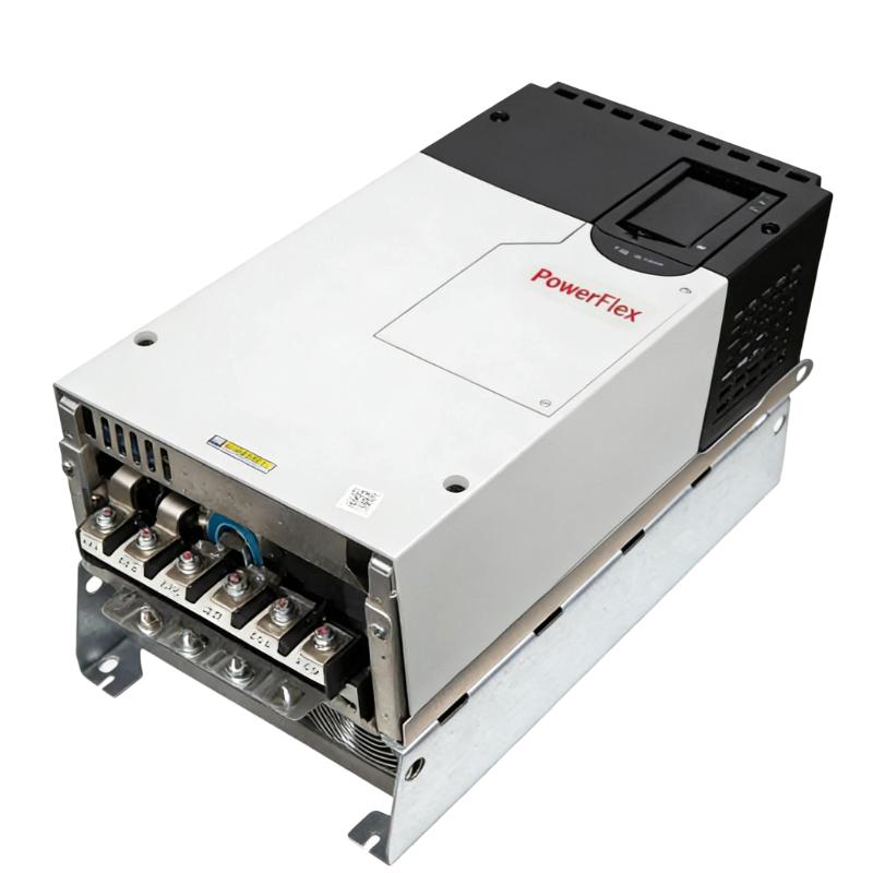
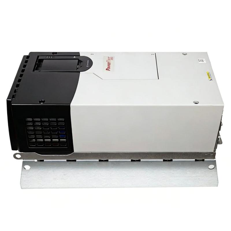
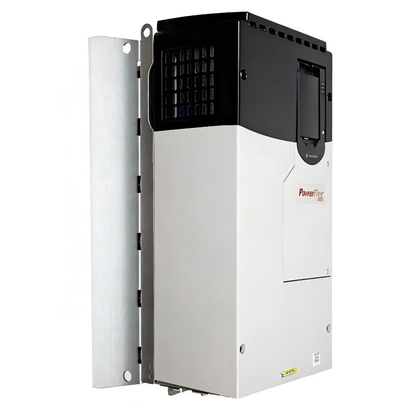
- Allen Bradley
- 20F1ANF142AA0NNNNN
- PowerFlex AC Drive
- USA
- 665.5 × 308 × 346.4 mm
- 38.6kg
- Xiamen, China
- New & In Stock
- T/T, PayPal, Western Union
- 1 Year
- 1-3 Working Days
- DHL, UPS, TNT, FedEx and EMS.
- 24-Hour Service
- COO
- 70
Our advantage

Global Logistics
We have a 10-year logistics and express cooperation agreement, so our products can be shipped to any place in the world.

Brand new and original
Our products are imported in bulk from the place of origin. Because of the cooperative relationship, our products are all original and 100% new.

24-hour service
We provide 7*24 hours service to our customers. We will be there whenever you need us.

Price advantage
All our products are priced very favorably because we have our own warehouse and supply.
| Company Information | |||
| [email protected] | |||
| Mobile | +8615980777398 | ||
| +8615980777398 | |||
| 15980777398 |
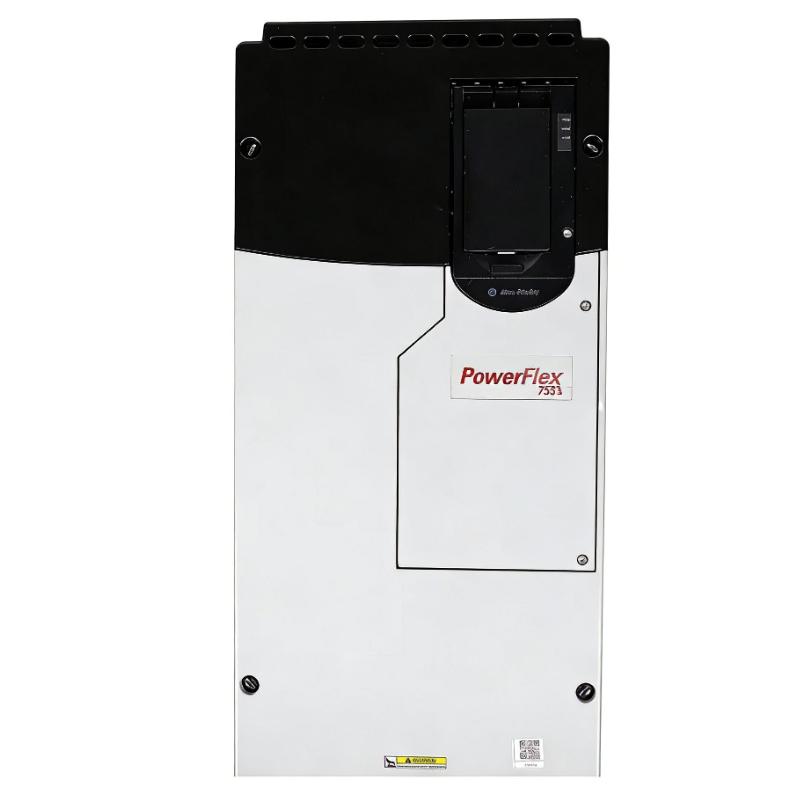
Allen-Bradley 20F1ANF142AA0NNNNN — Detailed Product Specifications, Introduction, Applications, Advantages and Related Model Recommendations
1. Product Overview
The Allen-Bradley 20F1ANF142AA0NNNNN is a high-power PowerFlex 753 AC variable-frequency drive designed for large three-phase industrial motor applications.
It is a 690 VAC, three-phase, 142 A drive with a 132 kW Normal Duty rating and a 110 kW Heavy Duty rating. The unit uses a Frame 6, forced-air-cooled, open-type construction and is intended for installation inside an appropriate industrial electrical cabinet or control enclosure.
A particularly important feature of this configuration is its integrated dynamic-braking transistor. This distinguishes it from the closely related 20F1ANF142JN0NNNNN, which has no internal dynamic-braking transistor.
The AA configuration also represents an EMC-filtered arrangement. The combination of high output capacity, 690 VAC operation, Frame 6 construction and integrated dynamic-braking capability makes this model suitable for large industrial machinery where both substantial motor power and controlled deceleration may be required.
The model is also configured without a local HIM, making it well suited to installations where the drive is operated through a PLC, HMI, industrial network or centralized control system.
One important point for equipment planning is that this exact catalog number has reached discontinued status. Therefore, it is best regarded as an existing/legacy PowerFlex 753 configuration for replacement, maintenance, retrofit or installed-base projects rather than as a current new-design selection. A closely related current configuration can be considered when a new installation is being designed.
2. Brand and Product Series
| Item | Specification |
|---|---|
| Brand | Allen-Bradley |
| Product Family | PowerFlex |
| Series | PowerFlex 753 |
| Product Type | AC Variable-Frequency Drive |
| Catalog Number | 20F1ANF142AA0NNNNN |
| Voltage Class | 690 VAC |
| Input Phase | 3 Phase |
| Output Phase | 3 Phase |
| Output Current | 142 A |
| Normal Duty Rating | 132 kW |
| Heavy Duty Rating | 110 kW |
| Frame | Frame 6 |
| Cooling | Forced Air |
| Enclosure | Open Type |
| Dynamic Braking | DB Transistor |
| EMC Configuration | EMC Filter |
| Input Configuration | AC Input with Precharge |
| DC Terminals | No |
| Embedded I/O | Yes |
| PID Capability | Yes |
| HIM | Blank / No HIM |
| Integrated Motion | No |
| Safety Functions | Supported |
| Approx. Weight | 48 kg |
| Approx. Dimensions | 665.5 × 308 × 346.4 mm |
The PowerFlex 753 series is an architecture-level AC drive family intended for general industrial applications where adjustable-speed motor control, integrated I/O, process functions and safety-related capabilities are important.
The 142 A configuration is near the upper end of the 690 VAC Frame 6 range and is intended for large motors and demanding industrial machinery.
3. Main Technical Parameters
| Parameter | Specification |
|---|---|
| Model | 20F1ANF142AA0NNNNN |
| Brand | Allen-Bradley |
| Series | PowerFlex 753 |
| Product Type | AC Variable-Frequency Drive |
| Input Voltage | 690 VAC |
| Input Phase | 3 Phase |
| Output Phase | 3 Phase |
| Rated Output Current | 142 A |
| Normal Duty Rating | 132 kW |
| Heavy Duty Rating | 110 kW |
| Input Frequency | 50/60 Hz |
| Input Type | AC Input with Precharge |
| DC Terminals | No |
| Dynamic Braking | Integrated DB Transistor |
| Filtering | EMC Filter |
| Cooling | Forced Air |
| Enclosure | Open Type |
| Protection | IP20/IP00, NEMA/UL Open Type |
| Frame Size | Frame 6 |
| Embedded I/O | Yes |
| PID Function | Yes |
| Integrated Motion | No |
| HIM | Blank / No HIM |
| Safety Functions | Yes |
| Height | Approx. 665.5 mm |
| Width | Approx. 308 mm |
| Depth | Approx. 346.4 mm |
| Dimensions | Approx. 665.5 × 308 × 346.4 mm |
| Weight | Approx. 48 kg |
| Installation | Cabinet / Panel |
| Cooling Method | Forced Air |
The three most important electrical values are 690 VAC, 142 A, and 132 kW Normal Duty / 110 kW Heavy Duty.
For actual engineering selection, the motor nameplate current, load profile, acceleration requirements, deceleration requirements and operating environment should be evaluated together rather than selecting the drive only from the motor’s nominal kW value.
4. Product Identification
The complete catalog number is:
20F1ANF142AA0NNNNN
This model number identifies a particular PowerFlex 753 configuration.
The important characteristics include:
- PowerFlex 753 platform
- 690 VAC class
- 142 A output-current class
- Frame 6
- Open-type construction
- Forced-air cooling
- AC input with precharge
- No DC terminals
- EMC-filtered configuration
- Integrated dynamic-braking transistor
- Blank/no-HIM configuration
This combination makes the model substantially different from another 142 A configuration that does not contain the internal dynamic-braking transistor.
5. Catalog Number Interpretation
| Catalog Section | General Meaning |
|---|---|
| 20F | PowerFlex 753 family |
| 1 | Standard drive configuration |
| A | AC input with precharge |
| N | Open-type enclosure |
| F | 690 VAC class |
| 142 | 142 A current class |
| A | EMC-filtered / braking configuration |
| A | Dynamic-braking transistor configuration |
| 0 | Blank / no HIM |
| NNNNN | No additional options represented |
The 142 section is especially important because it identifies the drive’s current class.
The F portion corresponds to the 690 VAC class.
The configuration also specifies an integrated dynamic-braking transistor, which is an important functional distinction for applications involving high-inertia loads and rapid deceleration.
6. Electrical Rating
The drive is rated for:
690 VAC / 3 Phase / 142 A
The primary power ratings are:
132 kW Normal Duty
110 kW Heavy Duty
| Electrical Parameter | Rating |
|---|---|
| Model | 20F1ANF142AA0NNNNN |
| Input Voltage | 690 VAC |
| Input Phase | 3 Phase |
| Output Phase | 3 Phase |
| Output Current | 142 A |
| Normal Duty | 132 kW |
| Heavy Duty | 110 kW |
| Frequency | 50/60 Hz |
| Input Arrangement | AC with Precharge |
| DC Terminals | No |
This is a large industrial drive intended for high-power motor systems.
The 690 VAC voltage class is particularly suitable for large industrial motors where a higher motor voltage is used to handle substantial mechanical power without requiring excessively high operating current.
7. 132 kW Normal Duty Rating
The 132 kW Normal Duty rating is the principal rating for variable-torque applications.
Typical applications include:
- Large centrifugal pumps
- Large cooling-water pumps
- Industrial ventilation fans
- Large blowers
- Air-handling equipment
- Process circulation systems
- Industrial utility equipment
- Large exhaust systems
In a variable-torque application, motor speed may change according to process demand.
The drive can therefore operate the motor at an appropriate speed instead of running continuously at full speed.
This is particularly useful in large pumping and ventilation systems.
8. 110 kW Heavy Duty Rating
The 110 kW Heavy Duty rating is intended for more demanding mechanical loads.
Potential applications include:
- Heavy conveyors
- Feeders
- Mixers
- Material-handling equipment
- Processing machinery
- Large production machinery
- High-load mechanical systems
Heavy Duty operation is especially important when the motor must provide greater torque or withstand more demanding acceleration and load conditions.
For this reason, a 132 kW motor should not automatically be assumed to be suitable for Heavy Duty operation simply because the drive has a 132 kW Normal Duty rating.
For Heavy Duty selection, the 110 kW rating should be used as the principal reference.
9. Normal Duty and Heavy Duty Comparison
| Duty Type | Power Rating | Typical Application |
|---|---|---|
| Normal Duty | 132 kW | Pumps, fans, blowers |
| Heavy Duty | 110 kW | Conveyors, mixers, feeders |
| Variable Torque | Up to 132 kW class | Centrifugal equipment |
| Constant Torque | Up to 110 kW class | Mechanical production equipment |
The actual motor current and load characteristics remain more important than the nominal motor power alone.
A proper selection should consider motor rated current, overload requirements, starting torque, acceleration time, load inertia and operating cycle.
10. Dynamic Braking
One of the most significant advantages of the 20F1ANF142AA0NNNNN is its integrated dynamic-braking transistor.
When a motor decelerates, its mechanical energy can be returned to the drive’s DC bus.
If the machine has substantial inertia, the regenerated energy can cause the DC-bus voltage to rise.
Dynamic braking provides a means of controlling this regenerated energy through an appropriate braking resistor arrangement.
This is particularly valuable in applications where the machine must stop faster than would be possible through ordinary ramped deceleration.
11. Why Dynamic Braking Matters
Dynamic braking can be useful when a machine has:
- High rotational inertia
- Heavy rotating components
- Frequent stopping
- Short deceleration times
- Repeated acceleration/deceleration cycles
- Rapid speed changes
- High-inertia fans
- Large conveyors
- Mixers
- Material-handling machinery
The integrated braking transistor means the drive has an important part of the braking system built into the drive configuration.
The complete braking system still needs to be engineered according to the application’s regenerative energy, braking resistor requirements and duty cycle.
12. Dynamic Braking vs. No Dynamic Braking
| Characteristic | 20F1ANF142AA0NNNNN | 20F1ANF142JN0NNNNN |
|---|---|---|
| Model | 20F1ANF142AA0NNNNN | 20F1ANF142JN0NNNNN |
| Voltage | 690 VAC | 690 VAC |
| Current | 142 A | 142 A |
| Normal Duty | 132 kW | 132 kW |
| Heavy Duty | 110 kW | 110 kW |
| Frame | 6 | 6 |
| Dynamic Braking | Integrated DB Transistor | None |
| Filtering | EMC Filter | Filtered |
| Cooling | Forced Air | Forced Air |
| Enclosure | Open Type | Open Type |
| Embedded I/O | Yes | Yes |
| PID | Yes | Yes |
| HIM | Blank / No HIM | Blank / No HIM |
| Dimensions | Approx. 665.5 × 308 × 346.4 mm | Approx. 665.5 × 308 × 346.4 mm class |
| Weight | Approx. 48 kg | Configuration dependent |
The two configurations have the same fundamental 690 VAC, 142 A, 132/110 kW power class.
The major practical difference is the braking and filtering configuration.
For high-inertia machinery, the AA configuration is particularly attractive because of the integrated dynamic-braking transistor.
13. EMC Filter Configuration
The model uses an EMC-filtered configuration.
This is important in industrial environments where electromagnetic compatibility is a major consideration.
A variable-frequency drive uses high-speed switching electronics to generate the motor waveform.
This switching can generate high-frequency electrical noise.
An EMC-oriented configuration can help manage conducted electromagnetic interference within the overall electrical system.
Good installation practices remain essential, including:
- Proper grounding
- Correct bonding
- Appropriate motor cable selection
- Cable shielding where required
- Correct routing
- Separation between power and sensitive control wiring
- Proper cabinet construction
14. AC Input with Precharge
The drive uses an AC input with precharge and no DC terminals.
The precharge function is important for controlling the charging process of the drive’s internal DC bus when power is applied.
This arrangement is part of the drive’s normal high-power electrical architecture.
The absence of external DC terminals is also significant when comparing this model with configurations intended for different DC-bus arrangements.
15. Frame 6 Mechanical Design
The drive uses a Frame 6 construction.
Frame size affects:
- Physical dimensions
- Mounting arrangement
- Cooling arrangement
- Cabinet layout
- Cable access
- Service access
- Overall panel design
The approximate physical dimensions are:
665.5 mm high × 308 mm wide × 346.4 mm deep
The approximate weight is:
48 kg
| Mechanical Parameter | Specification |
|---|---|
| Model | 20F1ANF142AA0NNNNN |
| Frame | 6 |
| Height | Approx. 665.5 mm |
| Width | Approx. 308 mm |
| Depth | Approx. 346.4 mm |
| Dimensions | Approx. 665.5 × 308 × 346.4 mm |
| Approx. Weight | 48 kg |
| Cooling | Forced Air |
| Enclosure | Open Type |
| Installation | Cabinet / Panel |
The 48 kg figure should be considered an approximate equipment weight for installation planning.
The final cabinet design should also account for mounting hardware, cables, bus connections, braking components and any additional option modules.
16. Open-Type Construction
The 20F1ANF142AA0NNNNN uses an open-type enclosure.
This means it is normally integrated into a suitable industrial electrical cabinet.
The cabinet provides the environmental protection required for the complete installation.
The enclosure should be designed to protect the drive from:
- Dust
- Moisture
- Oil contamination
- Conductive particles
- Chemical contamination
- Excessive humidity
- Mechanical contamination
The cabinet must also provide adequate airflow and heat removal.
17. Forced-Air Cooling
The drive uses forced-air cooling.
A 132 kW-class drive produces significant heat during operation.
Proper airflow is therefore essential.
The installation should provide:
- Clear air intake
- Clear hot-air exhaust
- Adequate cabinet ventilation
- Appropriate cooling-fan operation
- Sufficient service clearance
- Clean heat-dissipation surfaces
If several drives or power devices are installed in the same cabinet, the total cabinet thermal load should be calculated.
18. Embedded I/O
The PowerFlex 753 platform includes embedded I/O.
This is valuable because basic machine-control functions can be connected directly to the drive.
Typical applications include:
- Start command
- Stop command
- Enable
- Direction
- Speed reference
- Fault reset
- Status feedback
- Analog feedback
- Digital interlocks
This can reduce the number of separate interface components required in a control cabinet.
19. PID Control
The drive provides PID functionality.
PID control is particularly useful for process applications.
For example:
Pressure Sensor → PID Control → Drive → Motor → Pump
The sensor measures pressure.
The drive compares the measured value with the desired setpoint.
It then adjusts motor speed to help maintain the target pressure.
Similar control strategies can be used for:
- Flow
- Pressure
- Airflow
- Ventilation
- Water circulation
- Process utilities
This makes the PowerFlex 753 suitable for applications that require both motor-speed control and basic process regulation.
20. Blank / No-HIM Configuration
The model uses a blank/no-HIM configuration.
This is particularly useful in centralized automation systems.
For example:
PLC → Drive
or:
HMI → PLC → Drive
or:
Industrial Network → Drive
In these systems, operators can control the drive from a central interface without needing a permanently installed keypad on the drive itself.
This configuration is also useful where the drive is mounted inside an electrical cabinet and local operator access is not required.
21. Major Applications
| Application | Duty | Suitability |
|---|---|---|
| Large Centrifugal Pumps | Normal Duty | Excellent |
| Large Cooling Pumps | Normal Duty | Excellent |
| Industrial Water Systems | Normal Duty | Excellent |
| Large Fans | Normal Duty | Excellent |
| Large Blowers | Normal Duty | Excellent |
| Ventilation Systems | Normal Duty | Excellent |
| Air-Handling Systems | Normal Duty | Excellent |
| Process Circulation | Normal Duty | Excellent |
| Heavy Conveyors | Heavy Duty | Very Good |
| Feeders | Heavy Duty | Very Good |
| Mixers | Heavy Duty | Very Good |
| Material Handling | Heavy Duty | Very Good |
| High-Inertia Machinery | Application Dependent | Excellent |
| Process Machinery | Application Dependent | Very Good |
| Production Equipment | Application Dependent | Very Good |
22. Pump Applications
Large pumps are a particularly strong application for this drive.
Typical examples include:
- Industrial water transfer
- Cooling-water circulation
- Process-water systems
- Large utility pumps
- Pressure boosting
- Water treatment
- Industrial circulation
The 132 kW Normal Duty rating gives substantial capacity for large variable-torque pumping systems.
The PID function can also be useful when the system must maintain a pressure or flow-related setpoint.
23. Fan Applications
Large industrial fans can benefit significantly from variable-speed operation.
Potential applications include:
- Factory ventilation
- Industrial exhaust
- Process ventilation
- Cooling systems
- Air handling
- Extraction systems
- Large air-moving equipment
The drive allows fan speed to be adjusted according to actual system demand.
The integrated braking transistor may also be beneficial in high-inertia fan applications where faster controlled deceleration is required.
24. Blower Applications
Large blowers often require substantial motor power and can have significant rotating inertia.
The drive is suitable for applications such as:
- Process air
- Industrial ventilation
- Exhaust
- Cooling
- Air supply
- Industrial process systems
The drive can provide controlled acceleration and deceleration while allowing the blower speed to be adjusted to the process requirement.
25. Conveyor Applications
The 110 kW Heavy Duty rating makes the model suitable for many large conveyor systems.
Possible applications include:
- Bulk material handling
- Production conveyors
- Processing lines
- Heavy material transfer
- Industrial transportation systems
The integrated dynamic-braking transistor can be particularly useful when the conveyor has high inertia or needs controlled deceleration.
Important engineering factors include:
- Conveyor load
- Belt length
- Gearbox ratio
- Starting torque
- Acceleration time
- Deceleration time
- Mechanical inertia
- Braking frequency
- Motor current
26. Mixer Applications
Large industrial mixers can have considerable mechanical inertia.
They may also require different operating speeds during different process stages.
The drive can provide controlled acceleration and adjustable speed.
Potential benefits include reduced mechanical shock during starting and stopping.
The dynamic-braking capability is also useful when the mixer must decelerate relatively quickly.
Applications can include:
- Industrial mixing
- Process mixing
- Material blending
- Chemical process equipment
- Food-processing machinery
- Production machinery
27. Feeder Applications
Large feeders can require stable and adjustable speed.
The drive can be integrated with a PLC-based production system.
Possible control functions include:
- Start
- Stop
- Speed control
- Acceleration
- Deceleration
- Interlocking
- Fault indication
- Process synchronization
The embedded I/O provides useful options for integrating these functions.
28. Material Handling
Material-handling systems frequently involve large motors and significant mechanical inertia.
The 142 A drive can provide substantial motor-control capacity for properly sized systems.
Applications may include:
- Bulk material transfer
- Large conveyors
- Feeders
- Production lines
- Industrial handling equipment
- Processing systems
The dynamic-braking capability becomes particularly valuable when the material-handling machine must slow or stop quickly.
29. High-Inertia Machinery
This is one area where the 20F1ANF142AA0NNNNN can offer a meaningful advantage over a similar drive without an internal braking transistor.
Examples of high-inertia equipment include:
- Large fans
- Flywheel-driven equipment
- Large mixers
- Heavy rotating machines
- Large conveyors
- Centrifugal machinery
- Industrial rotating equipment
The braking system should still be correctly sized according to the machine’s actual inertia and operating cycle.
30. Product Advantages
| Advantage | Practical Benefit |
|---|---|
| 690 VAC Operation | Suitable for large industrial motors |
| 142 A Output | High motor-current capacity |
| 132 kW Normal Duty | Excellent for large variable-torque loads |
| 110 kW Heavy Duty | Strong capability for demanding mechanical loads |
| Integrated DB Transistor | Supports dynamic braking applications |
| EMC Filter | Helps address electromagnetic compatibility |
| Frame 6 | High-power industrial construction |
| Forced Air Cooling | Suitable for high-power operation |
| Embedded I/O | Simplifies control integration |
| PID Function | Useful for process regulation |
| No HIM | Suitable for centralized automation |
| Open Type | Flexible cabinet integration |
| 690 VAC Class | Appropriate for large motor systems |
31. Advantage — High Current Capacity
The 142 A output-current rating provides a substantial amount of motor-control capacity.
It is higher than the 119 A configuration and therefore provides additional current capability for larger motors.
This is useful when:
- Motor current exceeds the smaller drive rating
- Additional operating margin is required
- The load has demanding current requirements
- The application has higher torque demands
The actual motor current must still be checked against the drive’s applicable duty rating.
32. Advantage — 132 kW Normal Duty
The 132 kW Normal Duty rating makes this model particularly appropriate for large variable-torque loads.
Large pumps, fans and blowers often operate under changing process demand.
Variable-speed control allows the equipment to adjust its output rather than operating continuously at full speed.
This can improve process control and may reduce unnecessary energy consumption compared with fixed-speed operation under appropriate system conditions.
33. Advantage — 110 kW Heavy Duty
The 110 kW Heavy Duty rating provides a strong option for constant-torque applications.
This is important for:
- Conveyors
- Feeders
- Mixers
- Material handling
- Production equipment
- Mechanical processing
Heavy Duty applications should always be evaluated using the actual motor current and overload profile.
34. Advantage — Integrated Dynamic Braking
The integrated dynamic-braking transistor is one of the most valuable characteristics of this particular configuration.
It allows the drive to be used in applications where deceleration energy must be controlled.
This can be particularly useful when:
- The motor has high inertia
- The machine stops frequently
- The stopping time must be reduced
- The process requires rapid speed changes
- Controlled deceleration is important
This does not mean that every application requires a braking resistor. The complete braking system should be designed according to the actual regenerated energy and braking cycle.
35. Advantage — EMC Filter
The EMC-filtered configuration can be beneficial in electrically complex industrial environments.
A properly designed installation should combine the filter configuration with:
- Correct grounding
- Correct bonding
- Appropriate motor cable
- Proper shielding
- Controlled cable routing
- Separation of signal and power wiring
- Correct cabinet construction
This combination can help reduce electrical interference problems.
36. Advantage — Embedded I/O
Embedded I/O can simplify the control architecture.
It can reduce the need for additional interface components for basic drive-control functions.
This can result in:
- Less wiring
- Simplified panel design
- Reduced component count
- Easier commissioning
- More straightforward troubleshooting
For machine builders and system designers, this can be particularly useful.
37. Advantage — PID Functionality
PID control provides additional flexibility for process applications.
Instead of simply commanding a fixed motor speed, the drive can respond to feedback from the process.
This is valuable for:
- Pressure control
- Flow control
- Airflow control
- Pumping systems
- Ventilation
- Process circulation
It allows the drive to become part of the process-control strategy.
38. Advantage — Remote Operation
The blank/no-HIM configuration makes the drive well suited to centralized control systems.
For large industrial installations, operators often control equipment from a central control room.
The drive can remain inside the electrical cabinet while the operator works through a supervisory interface.
This can improve consistency across large machine installations.
39. Five Recommended Same-Series or Closely Related Models
| Model | Series | Voltage | Current | Normal Duty | Heavy Duty | Braking | Frame | Approx. Dimensions | Approx. Weight |
|---|---|---|---|---|---|---|---|---|---|
| 20F1ANF119AA0NNNNN | PowerFlex 753 | 690 VAC | 119 A | 110 kW | 90 kW | DB Transistor | 6 | 665.5 × 308 × 346.4 mm class | Approx. 48 kg class |
| 20F1ANF142JA0NNNNN | PowerFlex 753 | 690 VAC | 142 A | 132 kW | 110 kW | DB Transistor | 6 | 665.5 × 308 × 346.4 mm | Approx. 48 kg |
| 20F1ANF142JN0NNNNN | PowerFlex 753 | 690 VAC | 142 A | 132 kW | 110 kW | None | 6 | 665.5 × 308 × 346.4 mm class | Configuration dependent |
| 20F1ANF171JN0NNNNN | PowerFlex 753 | 690 VAC | 171 A | 160 kW | 132 kW | None | 7 | Frame 7 class | Configuration dependent |
| 20F1ANF119JN0NNNNN | PowerFlex 753 | 690 VAC | 119 A | 110 kW | 90 kW | None | 6 | 665.5 × 308 × 346.4 mm class | Approx. 38.6 kg class |
These models provide several useful alternatives depending on the motor size and braking requirements.
The 20F1ANF142JA0NNNNN is the closest modern configuration in terms of the same 142 A power class and integrated dynamic braking.
The 20F1ANF142JN0NNNNN provides the same current and power rating without the internal braking transistor.
The 20F1ANF119AA0NNNNN is a lower-capacity option while maintaining the same general configuration concept.
The 20F1ANF171JN0NNNNN provides a higher-power alternative for applications exceeding the 142 A range.
40. Recommended Model — 20F1ANF119AA0NNNNN
| Parameter | Specification |
|---|---|
| Model | 20F1ANF119AA0NNNNN |
| Series | PowerFlex 753 |
| Input Voltage | 690 VAC |
| Output Current | 119 A |
| Normal Duty | 110 kW |
| Heavy Duty | 90 kW |
| Frame | 6 |
| Dynamic Braking | DB Transistor |
| Filtering | EMC Filter |
| Cooling | Forced Air |
| Enclosure | Open Type |
| Embedded I/O | Yes |
| PID | Yes |
| HIM | Blank / No HIM |
| Dimensions | Frame 6 class |
| Weight | Approx. 48 kg class |
This is an attractive alternative when the application needs dynamic braking but does not require the full 142 A capacity.
41. Recommended Model — 20F1ANF142JA0NNNNN
| Parameter | Specification |
|---|---|
| Model | 20F1ANF142JA0NNNNN |
| Series | PowerFlex 753 |
| Input Voltage | 690 VAC |
| Output Current | 142 A |
| Normal Duty | 132 kW |
| Heavy Duty | 110 kW |
| Frame | 6 |
| Dynamic Braking | DB Transistor |
| Filtering | Filtered / CM Jumper Installed |
| Cooling | Forced Air |
| Enclosure | Open Type |
| Embedded I/O | Yes |
| PID | Yes |
| HIM | Blank / No HIM |
| Dimensions | 665.5 × 308 × 346.4 mm |
| Weight | Approx. 48 kg |
This is the most important related model to consider when replacing the original configuration.
It maintains the same fundamental 690 VAC, 142 A, 132/110 kW and Frame 6 ratings while retaining dynamic-braking capability.
42. Recommended Model — 20F1ANF142JN0NNNNN
| Parameter | Specification |
|---|---|
| Model | 20F1ANF142JN0NNNNN |
| Series | PowerFlex 753 |
| Input Voltage | 690 VAC |
| Output Current | 142 A |
| Normal Duty | 132 kW |
| Heavy Duty | 110 kW |
| Frame | 6 |
| Dynamic Braking | None |
| Filtering | Filtered |
| CM Jumper | Installed |
| Cooling | Forced Air |
| Enclosure | Open Type |
| Embedded I/O | Yes |
| PID | Yes |
| HIM | Blank / No HIM |
| Dimensions | 665.5 × 308 × 346.4 mm class |
| Weight | Configuration dependent |
This is a useful alternative when dynamic braking is not required.
It retains the same fundamental power capacity but has a different braking configuration.
43. Recommended Model — 20F1ANF171JN0NNNNN
| Parameter | Specification |
|---|---|
| Model | 20F1ANF171JN0NNNNN |
| Series | PowerFlex 753 |
| Input Voltage | 690 VAC |
| Output Current | 171 A |
| Normal Duty | 160 kW |
| Heavy Duty | 132 kW |
| Frame | 7 |
| Dynamic Braking | None |
| Cooling | Forced Air |
| Enclosure | Open Type |
| Embedded I/O | Yes |
| PID | Yes |
| HIM | Blank / No HIM |
| Dimensions | Frame 7 class |
| Weight | Configuration dependent |
This is the next significant capacity step above the 142 A configuration.
It is appropriate when the motor or load exceeds the practical capacity of the 142 A model.
The transition to Frame 7 should be taken into account during cabinet design.
44. Recommended Model — 20F1ANF119JN0NNNNN
| Parameter | Specification |
|---|---|
| Model | 20F1ANF119JN0NNNNN |
| Series | PowerFlex 753 |
| Input Voltage | 690 VAC |
| Output Current | 119 A |
| Normal Duty | 110 kW |
| Heavy Duty | 90 kW |
| Frame | 6 |
| Dynamic Braking | None |
| Cooling | Forced Air |
| Enclosure | Open Type |
| Embedded I/O | Yes |
| PID | Yes |
| Filtering | Filtered |
| CM Jumper | Installed |
| HIM | Blank / No HIM |
| Dimensions | 665.5 × 308 × 346.4 mm class |
| Weight | Approx. 38.6 kg class |
This is a good choice when the motor requirement is below the 142 A level and rapid dynamic braking is not required.
45. Five Representative Same-Brand Models
| Model | Series | Voltage Class | Current / Capacity | Normal Duty | Heavy Duty | Main Feature | Dimensions | Weight |
|---|---|---|---|---|---|---|---|---|
| 20F1ANF142JA0NNNNN | PowerFlex 753 | 690 VAC | 142 A | 132 kW | 110 kW | DB Transistor | 665.5 × 308 × 346.4 mm | Approx. 48 kg |
| 20F1ANF119JN0NNNNN | PowerFlex 753 | 690 VAC | 119 A | 110 kW | 90 kW | No Internal DB | 665.5 × 308 × 346.4 mm class | Approx. 38.6 kg |
| 20F1ANF171JN0NNNNN | PowerFlex 753 | 690 VAC | 171 A | 160 kW | 132 kW | Higher Capacity | Frame 7 class | Configuration dependent |
| 20G1ANC260JA0NNNNN | PowerFlex 755 | 400 VAC class | 260 A class | 132 kW class | 110 kW class | Advanced Drive Platform | Frame 6 class | Configuration dependent |
| 25B-D024N114 | PowerFlex 525 | 480 VAC class | 24 A class | 11 kW class | Application dependent | Compact Drive | Configuration dependent | Configuration dependent |
These five models represent useful choices across the same brand’s drive portfolio.
The first three are the closest technically related choices because they belong to the PowerFlex 753 family.
The PowerFlex 755 represents a more advanced drive platform for applications where additional control and application functions may be required.
The PowerFlex 525 represents a much smaller compact-drive class and is not a direct replacement for the 142 A model.
46. 690 VAC PowerFlex 753 Size Progression
| Model | Current | Normal Duty | Heavy Duty | Frame |
|---|---|---|---|---|
| 20F1ANF046JN0NNNNN | 46 A | 37 kW | 30 kW | 6 |
| 20F1ANF050JN0NNNNN | 50 A | 45 kW | 37 kW | 6 |
| 20F1ANF061JN0NNNNN | 61 A | 55 kW | 45 kW | 6 |
| 20F1ANF082JN0NNNNN | 82 A | 75 kW | 55 kW | 6 |
| 20F1ANF098JN0NNNNN | 98 A | 90 kW | 75 kW | 6 |
| 20F1ANF119JN0NNNNN | 119 A | 110 kW | 90 kW | 6 |
| 20F1ANF142JN0NNNNN | 142 A | 132 kW | 110 kW | 6 |
| 20F1ANF171JN0NNNNN | 171 A | 160 kW | 132 kW | 7 |
| 20F1ANF212JN0NNNNN | 212 A | 200 kW | 160 kW | 7 |
| 20F1ANF263JN0NNNNN | 263 A | 250 kW | 200 kW | 7 |
The 142 A configuration is one of the major capacity points in the 690 VAC PowerFlex 753 range.
It sits above the 119 A / 110 kW Normal Duty configuration and below the 171 A / 160 kW configuration.
This makes it a useful choice when a project requires more capacity than the 119 A model but does not yet require the next Frame 7 class.
47. 119 A vs. 142 A Comparison
| Parameter | 119 A Configuration | 142 A Configuration |
|---|---|---|
| Model | 20F1ANF119JN0NNNNN | 20F1ANF142AA0NNNNN |
| Voltage | 690 VAC | 690 VAC |
| Current | 119 A | 142 A |
| Normal Duty | 110 kW | 132 kW |
| Heavy Duty | 90 kW | 110 kW |
| Frame | 6 | 6 |
| Dynamic Braking | None | DB Transistor |
| Cooling | Forced Air | Forced Air |
| Embedded I/O | Yes | Yes |
| PID | Yes | Yes |
| Dimensions | 665.5 × 308 × 346.4 mm class | 665.5 × 308 × 346.4 mm |
| Weight | Approx. 38.6 kg class | Approx. 48 kg |
The 142 A configuration provides a substantial increase in electrical capacity.
It also adds integrated dynamic-braking capability in the AA configuration.
This makes the target model particularly attractive for applications where both high motor power and deceleration control are important.
48. Pump System Example
A typical large pump system can be arranged as:
Pressure Sensor → PID → 20F1ANF142AA0NNNNN → Motor → Pump
The pressure sensor provides process feedback.
The drive compares the feedback with the target pressure.
The motor speed is then adjusted according to the process requirement.
This arrangement can be useful for large:
- Water pumps
- Cooling pumps
- Process pumps
- Pressure systems
- Industrial circulation systems
49. Fan System Example
A large fan system can be arranged as:
Airflow Feedback → PID → Drive → Motor → Fan
The drive can change fan speed according to actual ventilation demand.
This can be useful in:
- Factory ventilation
- Industrial exhaust
- Process cooling
- Air handling
- Large extraction systems
Because large fans can have substantial inertia, the integrated dynamic-braking capability can be useful when controlled deceleration is required.
50. Conveyor System Example
A conveyor application may be arranged as:
PLC → Drive → Motor → Gearbox → Conveyor
The drive can manage:
- Start
- Stop
- Direction
- Speed
- Acceleration
- Deceleration
- Fault status
- Interlocking
The 110 kW Heavy Duty rating should be considered when evaluating constant-torque conveyor applications.
51. Mixer System Example
A large mixer can use:
PLC → Drive → Motor → Gearbox → Mixer
The drive provides controlled acceleration and adjustable operating speed.
During the production cycle, the mixer may operate at several different speeds.
When the machine needs to stop, the dynamic-braking system can help control the regenerated energy associated with the rotating mass.
52. Material-Handling System Example
A material-handling system can use:
Control System → Drive → Motor → Mechanical Transmission → Load
The drive can provide adjustable speed and controlled acceleration.
For high-inertia loads, controlled deceleration becomes particularly important.
The integrated dynamic-braking transistor therefore provides a useful capability for this class of machinery.
53. Cabinet Design
The approximate drive envelope is:
665.5 mm × 308 mm × 346.4 mm
The approximate drive weight is:
48 kg
The cabinet should provide more space than the bare dimensions indicate.
Additional space may be needed for:
- Incoming power cables
- Motor cables
- Control wiring
- Cable bending radius
- Grounding connections
- Braking components
- Ventilation
- Service access
- Maintenance
- Heat dissipation
The mounting structure should be capable of safely supporting the approximately 48 kg drive.
54. Thermal Management
Because this is a 132 kW-class drive, thermal management deserves careful attention.
The complete cabinet heat load may include:
- Drive losses
- Input components
- Reactors
- Contactors
- Power supplies
- Communication modules
- Braking components
- Other electrical equipment
The cooling system should therefore be designed for the entire enclosure.
Hot exhaust air should not be allowed to circulate back into the drive’s cooling intake.
55. Installation Considerations
A good installation should address:
- Electrical clearances
- Cabinet dimensions
- Cooling airflow
- Grounding
- EMC
- Motor cable routing
- Power cable routing
- Control wiring separation
- Maintenance access
- Ambient temperature
- Humidity
- Dust
- Mechanical vibration
The open-type construction means that the external cabinet plays an important role in environmental protection.
56. Maintenance Considerations
| Maintenance Item | Recommended Practice |
|---|---|
| Cooling Fan | Inspect regularly |
| Heat Sink | Keep clean |
| Airflow | Verify periodically |
| Cabinet Filters | Clean or replace |
| Power Connections | Inspect |
| Motor Connections | Inspect |
| Grounding | Verify |
| Control Wiring | Check |
| Braking Circuit | Inspect |
| Braking Resistor | Check condition |
| Cabinet Temperature | Monitor |
| Fault History | Review |
| Drive Parameters | Back up |
| Mounting Hardware | Inspect |
| Ventilation Paths | Keep clear |
For a high-power drive with dynamic braking, the braking system should receive particular attention during maintenance.
57. Dynamic-Braking System Considerations
The internal braking transistor is only one component of a complete dynamic-braking system.
The complete system may also involve:
- Braking resistor
- Proper resistor rating
- Correct resistance value
- Thermal capacity
- Braking duty cycle
- Deceleration time
- Motor inertia
- Load inertia
The braking resistor should be selected according to the actual regenerated energy and application duty cycle.
A large resistor is not automatically better.
The correct resistance and thermal capability are determined by the drive and machine requirements.
58. When This Model Is a Strong Choice
The 20F1ANF142AA0NNNNN is particularly attractive when a project requires:
- 690 VAC operation
- Three-phase motor control
- 142 A output capacity
- 132 kW Normal Duty
- 110 kW Heavy Duty
- Frame 6 construction
- Forced-air cooling
- Open-type cabinet installation
- EMC filtering
- Integrated dynamic braking
- Embedded I/O
- PID control
- No local HIM
It is particularly well suited to large industrial machinery where both motor capacity and deceleration control matter.
59. When Another Configuration May Be Better
A different model may be preferable when:
- Dynamic braking is not required
- A lower motor capacity is sufficient
- A larger motor is required
- A different voltage class is required
- A different enclosure arrangement is required
- A newer replacement configuration is preferred
For example, the 20F1ANF142JN0NNNNN is a useful choice when the same 142 A and 132/110 kW power class is required without an internal dynamic-braking transistor.
The 20F1ANF142JA0NNNNN is particularly relevant when replacing the target configuration while retaining dynamic-braking capability.
60. Important Lifecycle Consideration
The exact 20F1ANF142AA0NNNNN catalog number is a discontinued configuration.
This does not make the product irrelevant.
It can still be highly important for:
- Existing equipment
- Spare-parts planning
- Factory maintenance
- Retrofit projects
- Replacement of installed drives
- Repair inventories
- Legacy machine support
For a completely new project, however, it is generally more practical to evaluate the corresponding current configuration rather than designing a new system around a discontinued catalog number.
The closely related 20F1ANF142JA0NNNNN is an important replacement-oriented model to consider because it maintains the same 142 A, 690 VAC, 132 kW Normal Duty and 110 kW Heavy Duty class while retaining an internal dynamic-braking transistor.
61. Detailed Parameter Summary
| Category | Parameter | Specification |
|---|---|---|
| Identification | Model | 20F1ANF142AA0NNNNN |
| Identification | Brand | Allen-Bradley |
| Identification | Series | PowerFlex 753 |
| Identification | Product Type | AC Variable-Frequency Drive |
| Electrical | Input Voltage | 690 VAC |
| Electrical | Input Phase | 3 Phase |
| Electrical | Output Phase | 3 Phase |
| Electrical | Output Current | 142 A |
| Electrical | Normal Duty | 132 kW |
| Electrical | Heavy Duty | 110 kW |
| Electrical | Frequency | 50/60 Hz |
| Input | Input Type | AC Input with Precharge |
| Input | DC Terminals | No |
| Braking | Dynamic Braking | DB Transistor |
| EMC | Filtering | EMC Filter |
| Cooling | Cooling Method | Forced Air |
| Mechanical | Frame | 6 |
| Mechanical | Enclosure | Open Type |
| Mechanical | Protection | IP20/IP00, NEMA/UL Open Type |
| Control | Embedded I/O | Yes |
| Control | PID | Yes |
| Interface | HIM | Blank / No HIM |
| Motion | Integrated Motion | No |
| Safety | Safety Functions | Yes |
| Mechanical | Height | Approx. 665.5 mm |
| Mechanical | Width | Approx. 308 mm |
| Mechanical | Depth | Approx. 346.4 mm |
| Mechanical | Dimensions | Approx. 665.5 × 308 × 346.4 mm |
| Mechanical | Weight | Approx. 48 kg |
| Installation | Mounting | Cabinet / Panel |
| Cooling | Airflow | Forced Air |
| Application | Large Pumps | Excellent |
| Application | Large Fans | Excellent |
| Application | Large Blowers | Excellent |
| Application | Conveyors | Very Good |
| Application | Feeders | Very Good |
| Application | Mixers | Excellent |
| Application | Material Handling | Excellent |
| Application | High-Inertia Equipment | Excellent |
| Application | Process Machinery | Very Good |
62. Overall Advantages
| Feature | Practical Benefit |
|---|---|
| 690 VAC | Suitable for large industrial motors |
| 142 A | High output-current capacity |
| 132 kW ND | Strong variable-torque capability |
| 110 kW HD | Strong constant-torque capability |
| DB Transistor | Useful for controlled deceleration |
| EMC Filter | Supports EMC-oriented installations |
| Frame 6 | Large-capacity industrial platform |
| Forced Air | Suitable for high-power operation |
| Embedded I/O | Simplifies machine integration |
| PID | Supports process-control applications |
| No HIM | Suitable for centralized automation |
| Open Type | Flexible cabinet integration |
| AC Precharge | Appropriate high-power input architecture |
63. Final Assessment
The Allen-Bradley 20F1ANF142AA0NNNNN is a high-capacity PowerFlex 753 AC variable-frequency drive designed for large three-phase industrial motor applications.
Its core electrical rating is:
690 VAC / 3 Phase / 142 A / 132 kW Normal Duty / 110 kW Heavy Duty
Its mechanical configuration is:
Frame 6 / Forced Air Cooled / Open Type
Its approximate dimensions are:
665.5 × 308 × 346.4 mm
Its approximate weight is:
48 kg
The most important distinguishing feature of this particular configuration is its integrated dynamic-braking transistor.
That makes it especially interesting for applications involving substantial rotating inertia, frequent stopping, controlled deceleration or rapid speed changes.
The EMC-filtered configuration also makes it suitable for industrial electrical systems where electromagnetic compatibility needs to be considered as part of the overall drive installation.
The drive’s embedded I/O and PID functionality provide additional flexibility for machine control and process-control applications.
For large pumps, fans and blowers, the 132 kW Normal Duty rating provides substantial capacity.
For conveyors, mixers, feeders and other demanding mechanical systems, the 110 kW Heavy Duty rating provides a useful reference point.
The most closely related alternatives are the 20F1ANF142JA0NNNNN, 20F1ANF142JN0NNNNN, 20F1ANF119AA0NNNNN, 20F1ANF119JN0NNNNN and 20F1ANF171JN0NNNNN.
Among these, the 20F1ANF142JA0NNNNN is particularly important for replacement planning because it maintains the same general 142 A, 690 VAC, 132/110 kW and Frame 6 class while retaining dynamic-braking capability.
The 20F1ANF142JN0NNNNN is the better-related choice when dynamic braking is not needed.
The 20F1ANF119 configurations are suitable when the application requires less capacity, while the 20F1ANF171 configuration provides a higher-power step for larger motors.
Overall, the 20F1ANF142AA0NNNNN is a robust high-power industrial drive configuration with a particularly useful combination of 690 VAC operation, 142 A output capacity, 132 kW Normal Duty, 110 kW Heavy Duty, integrated dynamic braking, EMC filtering, embedded I/O, PID control, forced-air cooling and Frame 6 construction.
For an existing machine, it remains a significant model for maintenance and replacement work. For a new system, the closely related current configuration should be evaluated alongside the original model, especially when long-term availability and future maintenance are important.