
NewsNEWCENTER
Featured products
Contact Us
ABB 07EA63R1 (GJV3074353R1) Analog Input Module Installation Guide
2026-06-03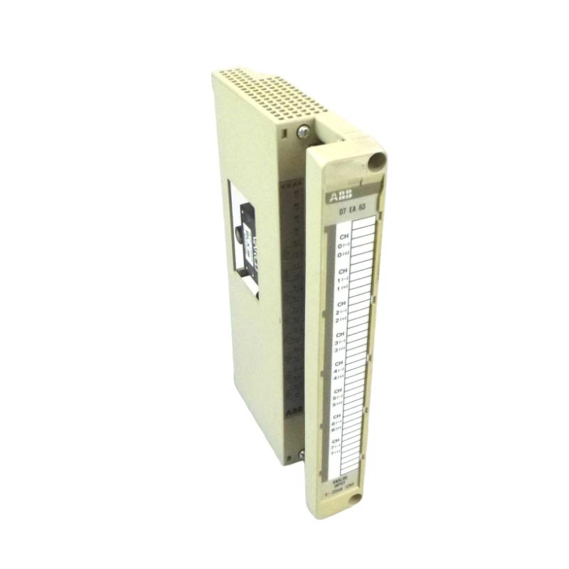
Table of Contents
- Installation Overview of ABB 07EA63R1 Analog Input Module
- Role of 07EA63R1 AI Module in Process Control
- Preparation Before Installation
- Mechanical Mounting and Rack Setup
- Analog Input Wiring and Signal Connections
- Module Commissioning & Calibration
- FAQs on ABB 07EA63R1 Installation
- Conclusion & Best Practices
Installation Overview of ABB 07EA63R1 Analog Input Module
ABB 07EA63R1 (GJV3074353R1) is a high-precision analog input module widely used in DCS/PLC systems. Proper installation ensures accurate 4–20 mA and 0–10 V signal acquisition. In field experience, incorrect slot alignment or wiring leads to intermittent input errors and signal drift.
Role of 07EA63R1 AI Module in Process Control
The 07EA63R1 module collects analog signals from transmitters and sensors, converts them to digital values for DCS/PLC processing, and enables precise process monitoring. Real-case observations show that stable AI module installation reduces false alarms and process deviations.
Preparation Before Installation
- Power off the control cabinet and verify lockout/tagout procedure
- Check module compatibility with ABB AC500/800xA rack
- Inspect terminal block, connectors, and mounting hardware
- Prepare shielded twisted-pair cables for analog signals
- Review configuration parameters for input range and signal type
Mechanical Mounting and Rack Setup
- Insert module into the designated rack slot with correct orientation
- Ensure backplane connector engages fully to avoid communication errors
- Maintain proper spacing between modules for heat dissipation
- Lock module in place using mechanical retention clips
- Field engineers recommend verifying alignment visually and mechanically
Analog Input Wiring and Signal Connections
Correct wiring is critical for signal integrity:
- Use shielded twisted-pair cables, separate from power lines
- Connect 4–20 mA or 0–10 V inputs according to module channel mapping
- Ensure single-point grounding to prevent ground loops
- Check terminal screws for proper torque (0.5–0.6 Nm)
Field example: one installation showed ±0.05 mA drift due to loose wiring, resolved after re-termination and grounding correction.
Module Commissioning & Calibration
- Power on module and confirm communication with PLC/DCS
- Load configuration parameters and verify channel mapping
- Check input scaling and calibration using precision meter
- Perform step response test to verify stability
- Document results for maintenance and troubleshooting
FAQs on ABB 07EA63R1 Installation
Can the module handle mixed 4–20 mA and 0–10 V signals?
Yes, but each channel must be configured individually in the engineering tool.
What is the maximum allowable cable length?
For 4–20 mA loops, keep cable length under 500 m; for voltage inputs, keep under 50 m to prevent voltage drop.
How to verify correct installation?
Measure input signals at terminals, check DCS/PLC reading, and confirm stable readings under process load conditions.
Conclusion & Best Practices
Proper installation and commissioning of ABB 07EA63R1 analog input module ensures accurate and reliable process measurement. Field experience confirms that careful wiring, grounding, and channel calibration are key factors in preventing signal errors and maximizing system uptime.