
NewsNEWCENTER
Featured products

Contact Us
Honeywell 05701-A-0283 Single Channel Control Card Installation Guide
2026-05-26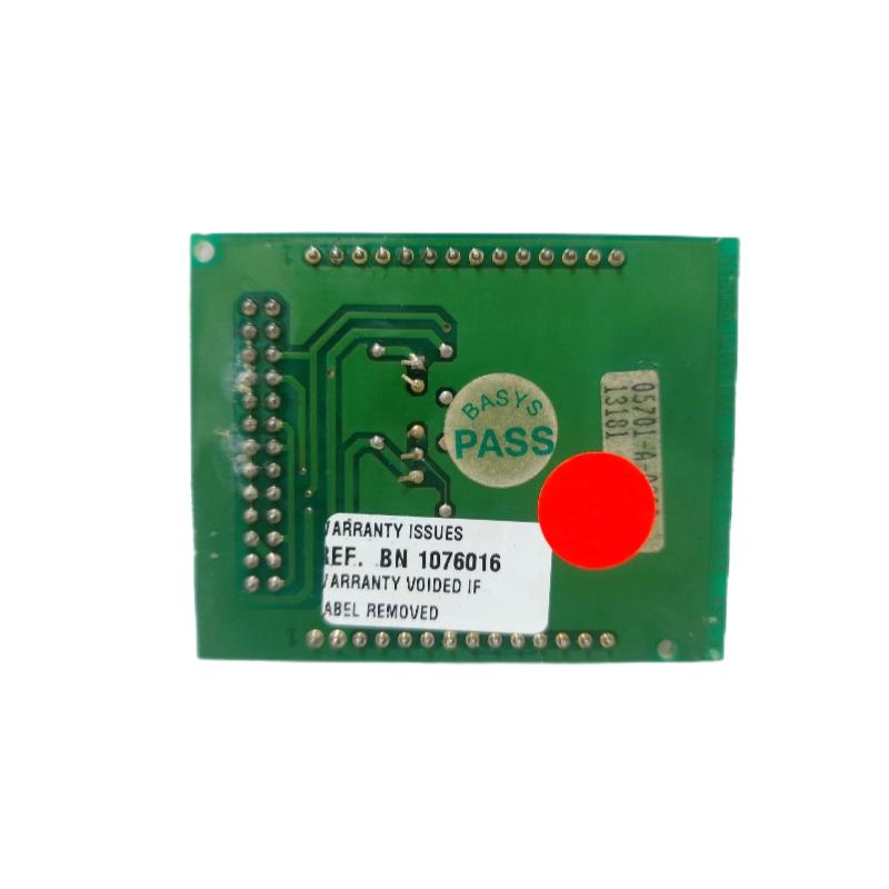
Honeywell 05701-A-0283 Single Channel Control Card startup problems are typically related to incorrect signal loop configuration, unstable 24VDC supply, or improper sensor calibration rather than control card failure. In industrial gas detection systems, installation quality directly affects alarm reliability and signal stability.
Contents
- Honeywell 05701-A-0283 Control Card Overview
- Honeywell 05701-A-0283 Installation Planning
- Honeywell 05701-A-0283 Wiring and Signal Integration
- Honeywell 05701-A-0283 Setup and System Configuration
- Honeywell 05701-A-0283 Commissioning Verification
- Honeywell 05701-A-0283 Field Installation Case
- Honeywell 05701-A-0283 Installation Questions
- Honeywell 05701-A-0283 Installation Summary
Honeywell 05701-A-0283 Control Card Overview
The Honeywell 05701-A-0283 Single Channel Control Card is designed for industrial gas monitoring systems requiring stable sensor input processing and reliable alarm output control. The module is commonly integrated into refinery safety systems, chemical process units, and hazardous area monitoring panels.
From field experience, the most common installation issue is unstable analog signal feedback caused by poor grounding or incorrect sensor loop polarity.
Honeywell 05701-A-0283 Installation Planning
Before installing the control card, engineers should verify cabinet layout and environmental conditions carefully.
- Recommended operating temperature: 0°C to 50°C
- Relative humidity: below 90% non-condensing
- Stable 24VDC power source required
- Avoid direct installation beside high-current contactors
- Maintain proper ventilation inside the cabinet
In one offshore platform project, unstable gas readings were traced to condensation forming near terminal blocks during night operation. After adding cabinet heating control, sensor stability improved significantly.
Honeywell 05701-A-0283 Wiring and Signal Integration
Signal integrity is critical during Honeywell 05701-A-0283 installation and commissioning.
Recommended Wiring Practice
- Separate analog signal wiring from power cables
- Use shielded twisted-pair cable for sensor input
- Connect shield grounding at one side only
- Verify relay output polarity carefully
- Check terminal torque before energizing
Control Card Input Verification
CHECK ANALOG INPUT
4mA = NORMAL ZERO SIGNAL
20mA = FULL SCALE INPUT

VERIFY POWER SUPPLY
24VDC ±5%

CHECK RELAY OUTPUT
NO/NC CONTACT STATUS
Loose analog terminals frequently create unstable gas concentration readings that appear as intermittent sensor faults.
Honeywell 05701-A-0283 Setup and System Configuration
Correct setup parameters are essential for accurate gas monitoring performance.
Commissioning engineers normally verify:
- Sensor type configuration
- Alarm threshold values
- Relay activation logic
- Analog output scaling
- Fault signal mapping
One common commissioning mistake is mismatched sensor range configuration. For example, a 0-100% LEL sensor incorrectly configured for ppm measurement can produce unstable alarms.
Recommended Startup Sequence
- Power supply energization
- Sensor warm-up stabilization
- Analog signal verification
- Alarm relay simulation
- Control room communication test
Honeywell 05701-A-0283 Commissioning Verification
Commissioning should confirm both signal stability and alarm response speed under actual operating conditions.
- Sensor response time
- Alarm activation delay
- Relay switching reliability
- Analog signal fluctuation
- Control card temperature rise
During one petrochemical commissioning project, engineers observed output fluctuation between 11.8mA and 13.5mA under stable gas conditions. Investigation later confirmed electromagnetic interference from nearby VFD cables.
After rerouting sensor cables, fluctuation reduced below 0.2mA.
Honeywell 05701-A-0283 Field Installation Case
In a gas compressor station, the Honeywell 05701-A-0283 Single Channel Control Card repeatedly generated false high-gas alarms during motor startup.
Initial suspicion focused on the gas detector itself. However, engineers noticed the alarm only appeared during compressor acceleration.
Field measurements showed:
- Ground voltage fluctuation: 2.9V
- Analog signal noise: ±1.8mA
- Cabinet temperature: 47°C
After improving cabinet grounding and relocating signal cables away from power wiring, the false alarms disappeared completely.
Honeywell 05701-A-0283 Installation Questions
Why does the Honeywell 05701-A-0283 Control Card show unstable gas readings?
The most common causes include electrical noise, poor shielding, loose terminals, or unstable sensor power supply.
Can the control card share grounding with inverter equipment?
Independent instrumentation grounding is strongly recommended to reduce signal interference and prevent false alarms.
Why is sensor warm-up important during commissioning?
Gas sensors require stabilization time before accurate signal output can be achieved. Immediate calibration after startup may produce incorrect readings.
What is the most frequent installation issue?
Incorrect analog loop polarity and poor shield termination are among the most common field installation problems.
Honeywell 05701-A-0283 Installation Summary
Reliable Honeywell 05701-A-0283 Single Channel Control Card installation depends on proper wiring practices, stable power supply conditions, accurate system configuration, and structured commissioning validation. In industrial safety systems, signal integrity and grounding quality are often more important than hardware replacement when ensuring long-term monitoring stability.