

ProductPRODUCT
Featured products
Contact Us
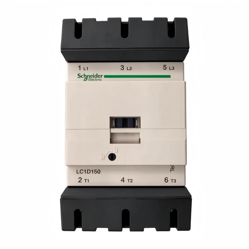
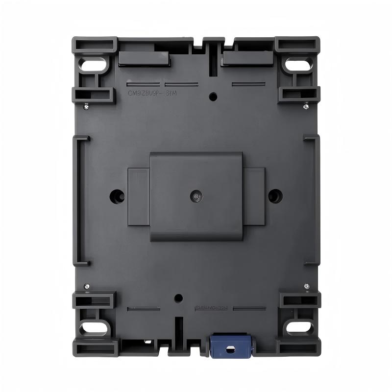
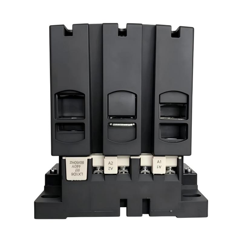
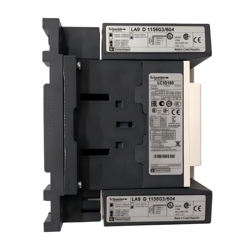
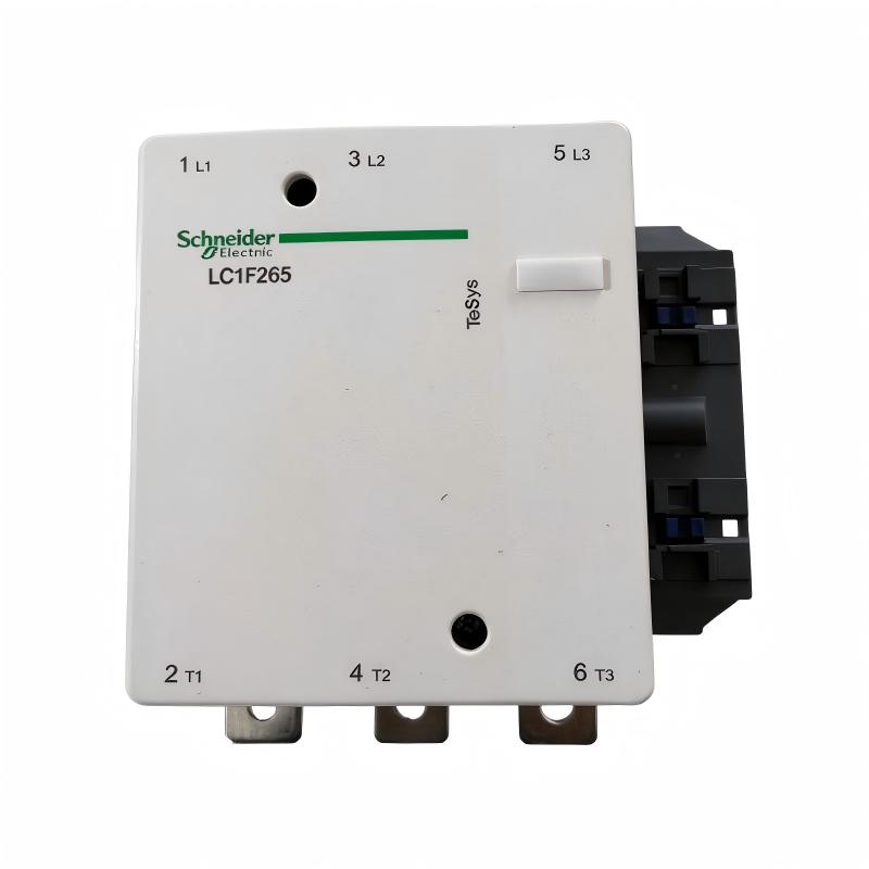
- Schneider
- LC1D150R7
- Contactor
- France
- 158 x 120 x 136 mm
- 2.5 kg
- Xiamen, China
- New & In Stock
- T/T, PayPal, Western Union
- 1 Year
- 1-3 Working Days
- DHL, UPS, TNT, FedEx and EMS.
- 24-Hour Service
- COO
- 5
Our advantage

Global Logistics
We have a 10-year logistics and express cooperation agreement, so our products can be shipped to any place in the world.

Brand new and original
Our products are imported in bulk from the place of origin. Because of the cooperative relationship, our products are all original and 100% new.

24-hour service
We provide 7*24 hours service to our customers. We will be there whenever you need us.

Price advantage
All our products are priced very favorably because we have our own warehouse and supply.
| Company Information | |||
| [email protected] | |||
| Mobile | +8615980777398 | ||
| +8615980777398 | |||
| 15980777398 |
Product Overview
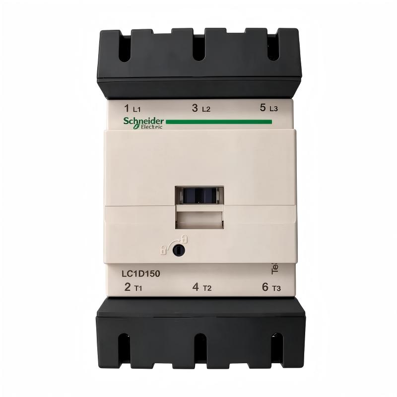
The Schneider Electric LC1D150R7 TeSys D Contactor is a heavy-duty three-pole electromagnetic contactor designed for switching and controlling electrical power circuits in industrial applications. It is part of Schneider Electric’s TeSys D contactor range and is suitable for motor control and resistive-load switching.
Contactors are essential components in industrial electrical systems. They allow control circuits to operate higher-power loads without requiring operators or low-voltage control devices to switch the main power circuit directly. When the coil receives the specified control voltage, the electromagnetic mechanism changes the position of the main contacts, allowing the connected load to be energized or disconnected.
The LC1D150R7 features three normally open main power contacts and is rated for 150 A under the AC-3 utilization category at up to 440 V AC. Its AC-1 conventional operational current rating is 200 A under the specified conditions. The contactor uses a 440 V AC, 50/60 Hz control coil, making coil-voltage verification particularly important when selecting a replacement.
For motor-control applications, this model supports a rated operating power of 75 kW at 380–400 V AC under AC-3 conditions. It also includes auxiliary contacts with a 1 NO + 1 NC configuration, which can be used for status indication, electrical interlocking, and control-circuit functions.
The LC1D150R7 is designed for industrial control panels, motor starters, production machinery, and other installations requiring reliable switching of three-phase loads. Its mechanical construction and electrical ratings make it suitable for applications where contactor operation is an important part of the equipment’s control and protection architecture.
Technical Specifications
| Parameter | Specification |
|---|---|
| Brand | Schneider Electric |
| Product Series | TeSys D |
| Model | LC1D150R7 |
| Product Type | AC Contactor |
| Contactor Application | Motor Control / Resistive Load |
| Number of Poles | 3 Poles |
| Main Contact Configuration | 3 NO |
| AC-3 Rated Operational Current | 150 A |
| AC-1 Rated Operational Current | 200 A |
| Rated Operational Voltage | Up to 440 V AC for specified AC-3 rating |
| Coil Voltage | 440 V AC |
| Coil Frequency | 50/60 Hz |
| Motor Power at 380–400 V AC | 75 kW, AC-3 |
| Motor Power at 415–440 V AC | 80 kW, AC-3 |
| Motor Power at 500 V AC | 90 kW, AC-3 |
| Motor Power at 660–690 V AC | 100 kW, AC-3 |
| Auxiliary Contacts | 1 NO + 1 NC |
| Auxiliary Contact Type | Mechanically linked and mirror contact functions |
| Rated Insulation Voltage | 600 V, UL/CSA power circuit rating |
| Rated Impulse Withstand Voltage | 8 kV |
| Mounting | Panel / Rail, subject to installation arrangement |
| Dimensions | 158 × 120 × 136 mm |
| Weight | 2.5 kg |
| Product Family | TeSys D |
| Lifecycle Status | Scheduled for discontinuation on December 31, 2026 |
Electrical ratings depend on utilization category, operating voltage, ambient temperature, and installation conditions. Always refer to the product documentation when selecting the contactor for a specific load.
Function and Working Principle
The LC1D150R7 operates through an electromagnetic switching mechanism. Its main function is to connect or disconnect the power supply to an electrical load in response to a control signal.
1. Electromagnetic Coil Operation
The contactor contains a control coil rated at 440 V AC, 50/60 Hz. When the correct voltage is applied to the coil, an electromagnetic field is generated.
This magnetic field attracts the moving armature and changes the position of the main contacts. When the coil is de-energized, the return mechanism moves the contacts back to their normal state.
The coil voltage must match the control circuit. Applying an incorrect voltage can cause unreliable operation, overheating, or damage to the coil.
2. Main Contact Switching
The LC1D150R7 has three normally open main contacts. These contacts are used to switch the three phases of a compatible electrical load.
When the contactor is energized, the three main contacts close and allow current to flow to the connected motor or other load. When the coil is de-energized, the contacts open and interrupt the power circuit.
The 150 A AC-3 rating is intended for specified motor-switching conditions. It should not be confused with the 200 A AC-1 rating, which applies to resistive or slightly inductive loads under different operating conditions.
3. Auxiliary Contact Operation
The contactor includes one normally open and one normally closed auxiliary contact.
These contacts are commonly used in control circuits for:
- Contactor status feedback.
- Electrical interlocking.
- Start and stop circuit logic.
- PLC input signals.
- Alarm and operating-status indication.
Auxiliary contacts allow the control system to monitor or coordinate the contactor without using the main power contacts for low-current signaling.
4. Motor Switching
When used in an AC-3 motor-control application, the contactor is designed to make and break motor currents under the conditions defined for that utilization category.
During motor starting, the contactor connects the motor to the power supply. When a stop command is issued, the contactor disconnects the motor according to the control circuit design.
The contactor does not independently provide complete motor overload or short-circuit protection. Suitable overload relays and upstream protective devices must be selected as part of the motor starter assembly.
Role in Industrial Control Systems
The LC1D150R7 can serve as the main switching device in an industrial motor starter or electrical control panel. It connects the control system’s commands with the high-current power circuit.
PLC-Based Control
A programmable logic controller can control the contactor through an appropriately rated interface or interposing relay. The PLC processes signals from sensors, operator controls, and machine logic before issuing a command to energize or de-energize the contactor coil.
The auxiliary contacts can provide feedback to PLC inputs, allowing the controller to monitor the contactor’s operating state.
The PLC output must not be connected directly to the 440 V AC coil unless the output device is specifically rated for that voltage and switching duty. A suitable interface arrangement is normally required.
Motor Starter Integration
The contactor can be incorporated into a motor starter together with:
- A thermal or electronic overload relay.
- Upstream circuit breakers or fuses.
- Control transformers or control power supplies, where required.
- Start and stop push buttons.
- Emergency-stop and safety control devices.
- Auxiliary relays and terminal blocks.
The final arrangement depends on the motor rating, protection requirements, and applicable electrical standards.
Electrical Interlocking
Auxiliary contacts can support interlocking between contactors. For example, a control circuit may prevent two contactors from energizing simultaneously when their operation could create an unsafe or unwanted electrical condition.
Mechanical and electrical interlocking arrangements should be selected according to the specific circuit design.
Industrial Applications
The LC1D150R7 is suitable for industrial power-switching applications that fall within its electrical ratings and utilization categories.
1. Industrial Motor Control
Three-phase motors are widely used in manufacturing facilities, processing plants, and industrial machinery. The LC1D150R7 can serve as the main switching contactor in a motor starter for compatible motors.
Its 150 A AC-3 rating and 75 kW motor rating at 380–400 V AC make it suitable for appropriately rated motor-control applications.
2. Pumping Systems
Industrial pumping equipment often operates continuously or according to process demand. A contactor can connect and disconnect the pump motor under the control of a PLC, pressure switch, level controller, or operator station.
The overload relay and short-circuit protection must be selected separately to match the motor and installation.
3. Fan and Ventilation Equipment
Large ventilation systems and industrial fans use contactors as part of their motor-control circuits. The LC1D150R7 may be used where the motor current and switching duty are within its ratings.
Control logic can coordinate fan operation with temperature sensors, airflow monitoring, and building or process automation systems.
4. Compressor Systems
Industrial compressors require dependable motor switching and coordinated protection. A contactor can be integrated into the compressor’s electrical starter circuit to control motor energization.
The contactor must be selected according to the compressor motor’s starting characteristics and operating duty. Frequent starting and stopping should be assessed against the contactor’s electrical durability ratings.
5. Manufacturing and Processing Machinery
Production equipment may use contactors to control motors, auxiliary machinery, and other electrical loads. The LC1D150R7 can be incorporated into control panels where a three-phase switching device with a 440 V AC coil is required.
6. Industrial Distribution and Control Panels
The contactor can also be installed in industrial electrical panels as part of a machine-control or power-switching arrangement. Its auxiliary contacts provide additional control and signaling possibilities for the panel designer.
Installation and System Integration
Correct installation is essential for electrical safety, reliable switching, and long-term contact performance.
1. Verify the Coil Voltage
The LC1D150R7 uses a 440 V AC, 50/60 Hz coil. Before installation, confirm that the control circuit supplies the correct voltage and frequency.
Do not assume that another LC1D150 variant has the same coil rating. Different suffixes identify different coil voltages and configurations.
2. Confirm Main Circuit Ratings
Check the motor nameplate and application requirements before connecting the main power circuit. The contactor’s 150 A AC-3 rating should be evaluated against the motor’s rated current and operating conditions.
For resistive loads, the AC-1 rating may be relevant, but it should not be substituted for the AC-3 rating in motor applications.
3. Mounting and Panel Space
The supplied dimensions are 158 × 120 × 136 mm, with a product weight of 2.5 kg.
Confirm the actual mounting arrangement and clearances before installing the contactor in a panel. Provide sufficient space for power conductors, coil wiring, auxiliary wiring, inspection, and maintenance.
4. Main Circuit Wiring
Connect the three main power phases according to the manufacturer’s terminal markings and wiring instructions.
Use conductors with suitable cross-sectional areas and insulation ratings. Tighten terminals to the specified torque and check that conductors are properly secured.
5. Auxiliary Circuit Wiring
The 1 NO + 1 NC auxiliary contacts can be connected to PLC inputs, interlocking circuits, or status indicators.
Verify the contact ratings and wiring diagram before using auxiliary contacts in control or safety-related circuits. A standard auxiliary contact should not automatically be treated as a certified safety contact.
6. Overload and Short-Circuit Protection
The contactor is a switching device, not a complete protective system. Select suitable overload protection according to the motor’s rated current and application.
Upstream fuses or circuit breakers must also be coordinated with the contactor and the installation’s available short-circuit current.
7. Commissioning and Inspection
Before energizing the system:
- Inspect the contactor body and terminals.
- Confirm the coil voltage.
- Check the phase connections.
- Verify overload relay settings.
- Confirm the auxiliary contact wiring.
- Test the control circuit.
- Check for abnormal noise, vibration, or heating during operation.
Disconnect and isolate the power supply before carrying out maintenance or terminal inspections.
Compatible System Components
The LC1D150R7 is normally used with additional electrical and automation components to form a complete motor-control system.
| Component | Function | Integration Considerations |
|---|---|---|
| Three-phase AC motor | Converts electrical energy into mechanical power | Match motor current and starting characteristics to the contactor rating |
| Thermal overload relay | Protects the motor against overload conditions | Select according to motor full-load current |
| Circuit breaker | Provides upstream circuit protection | Coordinate with the contactor and installation fault level |
| Industrial fuse | Provides short-circuit protection | Select according to manufacturer coordination guidance |
| PLC | Controls contactor operation | Use a suitable interface for the 440 V AC coil |
| Interposing relay | Interfaces PLC outputs with the contactor coil circuit | Verify coil and contact ratings |
| Auxiliary relay | Expands control logic and signaling functions | Confirm electrical compatibility |
| Push buttons | Provide manual start and stop commands | Integrate with the control circuit |
| HMI | Provides operator commands and status displays | Typically communicates through the PLC |
| Control transformer | Supplies an appropriate control voltage where required | Ensure the selected voltage matches the control equipment |
| Terminal blocks | Organize power and control wiring | Select suitable current and voltage ratings |
The components listed above are examples of equipment that may be used in a complete installation. They are not necessarily supplied with the contactor.
Alternative Models and Replacement Considerations
When replacing the LC1D150R7, the complete electrical and mechanical configuration must be checked. A contactor with the same current rating may still have a different coil voltage, terminal arrangement, or accessory configuration.
| Alternative Model | Replacement Considerations |
|---|---|
| Schneider Electric LC1D150ALSE | Manufacturer-listed replacement; verify coil selection and connector/terminal arrangement |
| Schneider Electric LC1D150G7 | Related 150 A TeSys D contactor variant with a different coil voltage |
| Schneider Electric LC1D150M7 | Related TeSys D model with a different coil voltage |
| Schneider Electric LC1D150F7 | Related 150 A contactor variant; verify its coil and connection configuration |
| Other TeSys D 150 A contactors | Compare utilization category, rated current, coil voltage, auxiliary contacts, and dimensions |
Before approving a replacement, check:
- Three-pole main contact configuration.
- 150 A AC-3 rated operational current.
- 200 A AC-1 rated operational current where applicable.
- 440 V AC, 50/60 Hz coil requirement.
- 1 NO + 1 NC auxiliary contact arrangement.
- Main terminal and coil terminal layout.
- Mounting dimensions and fixing points.
- Required electrical and mechanical accessories.
- Coordination with overload and short-circuit protection.
The LC1D150ALSE is listed by Schneider Electric as a recommended replacement. However, it should not be treated as an unconditional drop-in replacement. Confirm the selected coil voltage, connection system, installation dimensions, and control-circuit requirements before substitution.
Key Advantages
High Current Switching Capability
The 150 A AC-3 rating supports industrial motor-control applications within the specified operating conditions. Its 200 A AC-1 rating provides a separate reference for applicable resistive-load duties.
Three-Pole Main Contacts
The three normally open main contacts allow the contactor to switch a three-phase power circuit.
Integrated Auxiliary Contacts
The 1 NO + 1 NC auxiliary contact arrangement supports status feedback, interlocking, and control-circuit logic.
440 V AC Control Coil
The 440 V AC, 50/60 Hz coil allows integration into control systems designed for this specific control voltage.
Industrial Motor Control
The contactor is designed for AC-3 motor-switching applications and supports a rated motor power of 75 kW at 380–400 V AC under the specified conditions.
Established TeSys D Product Family
The TeSys D range provides a recognized contactor platform for industrial motor starters and electrical control panels.
Maintenance and Replacement Identification
The complete LC1D150R7 reference helps maintenance teams distinguish this 440 V AC coil version from other contactors with similar current ratings but different control configurations.
Technical FAQs
1. What is the Schneider Electric LC1D150R7?
The LC1D150R7 is a three-pole TeSys D AC contactor designed for industrial motor control and resistive-load switching. It has a 150 A AC-3 rating and a 440 V AC, 50/60 Hz control coil.
2. What is the rated current of the LC1D150R7?
Its rated operational current is 150 A under AC-3 conditions at up to 440 V AC. Its AC-1 rating is 200 A under the specified conditions.
3. What coil voltage does this contactor use?
The LC1D150R7 uses a 440 V AC coil at 50/60 Hz. The control supply must match this specification.
4. How many main poles does it have?
It has three main poles, with three normally open main contacts. It is intended for switching compatible three-phase electrical circuits.
5. What auxiliary contacts are included?
The contactor includes one normally open and one normally closed auxiliary contact. These can support status signaling and control-circuit functions.
6. What motor power can it handle?
The documented AC-3 motor rating is 75 kW at 380–400 V AC. The applicable rating changes with operating voltage and utilization category.
7. Can the LC1D150R7 be used with a PLC?
Yes. A PLC can control the contactor through an appropriately rated output interface or interposing relay. The 440 V AC coil must not be connected to an output that is not rated for that voltage.
8. Does the contactor provide motor overload protection?
No. The contactor switches the motor power circuit but does not replace a motor overload relay or suitable short-circuit protection. These protective devices must be selected separately.
9. Is the LC1D150R7 being discontinued?
Schneider Electric’s current product information lists December 31, 2026 as the planned date for discontinuation of commercialization. The manufacturer also identifies LC1D150ALSE as a recommended replacement. Check regional availability and service arrangements before purchasing.
10. What should be checked before ordering a replacement?
Verify the complete model number, coil voltage, main contact rating, auxiliary contacts, terminal arrangement, dimensions, mounting requirements, and compatibility with the existing overload and protection devices.
Procurement and Maintenance Recommendations
When purchasing the Schneider Electric LC1D150R7, always verify the complete catalog number. The final suffix is important because it identifies the coil configuration. A contactor with the same 150 A rating but a different coil voltage may not work in the existing control circuit.
For replacement projects, compare the contactor’s electrical ratings with the motor nameplate and the actual operating conditions. Check whether the application uses AC-3 motor switching or another utilization category. Also verify the overload relay, upstream circuit protection, and available short-circuit current.
For used or surplus units, request clear photographs of the nameplate, main terminals, coil terminals, and auxiliary contacts. Check for signs of overheating, damaged insulation, worn contact surfaces, or mechanical sticking. Confirm the product’s test condition and warranty terms before purchase.
During routine maintenance, inspect terminals for looseness or discoloration, check the contactor’s operating sound, and examine the condition of the main and auxiliary contacts according to the maintenance schedule. Always isolate the power supply before servicing.
Because the model is scheduled for discontinuation at the end of 2026, maintenance teams should review spare-parts requirements and evaluate the manufacturer’s recommended replacement. Any replacement should be checked for coil voltage, connection method, mounting dimensions, and control-circuit compatibility before installation.
Conclusion
The Schneider Electric LC1D150R7 TeSys D Contactor is a three-pole industrial switching device with a 150 A AC-3 rating, 200 A AC-1 rating, and a 440 V AC, 50/60 Hz control coil. Its 1 NO + 1 NC auxiliary contacts support control feedback and interlocking functions, while its motor-control rating reaches 75 kW at 380–400 V AC under AC-3 conditions.
With dimensions of 158 × 120 × 136 mm and a weight of 2.5 kg, the LC1D150R7 is designed for integration into industrial motor starters and electrical control panels. Accurate coil-voltage verification, appropriate overload protection, and careful replacement assessment are essential for reliable operation.