
NewsNEWCENTER
Featured products
Contact Us
GE 8610-FT-NA Field Terminal: Troubleshooting, Fault Diagnosis and Maintenance Guide
2026-11-06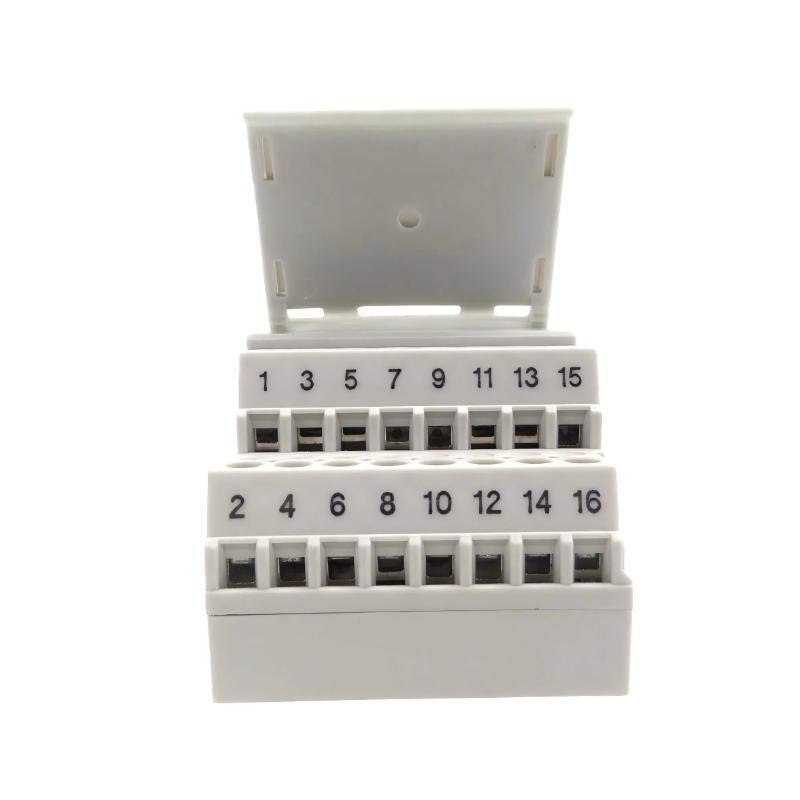
1. Introduction
The GE 8610-FT-NA is a non-arcing field terminal used in compatible industrial I/O installations. It provides termination points for field wiring between instruments and control system equipment. Reliable electrical connections at the field terminal are essential for accurate signal transmission and stable operation of the associated I/O channels. Although the 8610-FT-NA is a passive field wiring component, problems involving loose conductors, incorrect terminal assignments, damaged connections, or incompatible field circuits can affect the performance of the entire control system. Typical symptoms include missing signals, intermittent channel states, unstable analog readings, and unexpected I/O alarms. This guide explains how to diagnose common problems associated with the GE 8610-FT-NA, inspect field wiring, verify channel operation, and prevent recurring termination faults.
2. Product Identification and Key Characteristics
Before troubleshooting, confirm that the installed component is the correct field terminal.
| Parameter | Specification |
|---|---|
| Manufacturer | GE |
| Model | 8610-FT-NA |
| Product Type | Non-Arcing Field Terminal |
| Product Family | 8000 Series |
| Application | Field wiring termination for compatible I/O equipment |
| Rated Voltage | 250 VAC, subject to the complete system ratings |
| Maximum Channel Current | 3 A per I/O channel |
| Conductor Size | 0.14–2.5 mm² |
| Fuse Configuration | Unfused terminal type |
The 8610-FT-NA is not a fused terminal and is not an intrinsically safe barrier. Its non-arcing designation applies only under the conditions specified for the complete approved installation. Before conducting electrical tests, verify the ratings, terminal assignments, and installation conditions against the exact I/O module documentation.
3. Common Symptoms and Possible Causes
The following table provides a starting point for fault diagnosis.
| Symptom | Possible Cause | Recommended Inspection |
|---|---|---|
| No signal reaches the controller | Open circuit, disconnected conductor, incorrect terminal assignment, or field device fault | Trace the complete field circuit and verify connections |
| Intermittent signal | Loose screw-clamp connection, damaged conductor, or unstable field device | Inspect wiring and connection condition |
| Incorrect digital input state | Incorrect polarity, wrong channel wiring, or incompatible signal level | Compare wiring with the I/O module diagram |
| Unstable analog measurement | Poor termination, grounding issue, cable interference, or field instrument fault | Inspect signal wiring, shielding, and instrument output |
| Multiple channels fail | Shared wiring problem, common connection fault, or I/O module issue | Check common circuits and associated module diagnostics |
| Unexpected short-circuit indication | Damaged insulation, incorrect wiring, or shorted field device | Isolate the affected circuit and inspect the wiring |
| Fault appears after maintenance | Incorrect reconnection, misplaced conductor, or damaged terminal | Compare the current wiring with the approved drawings |
A field terminal fault should not be diagnosed solely from a controller alarm. The field device, cable, terminal, I/O module, and control system configuration form a complete signal path and should be checked systematically.
4. Safety Precautions Before Troubleshooting
The 8610-FT-NA may be installed in industrial environments and specified hazardous-area applications. Troubleshooting must be performed by qualified personnel following the applicable electrical and hazardous-area procedures. Before handling the terminal:
- Review the installation drawings and equipment identification.
- Apply the site’s lockout/tagout procedure before disconnecting wiring.
- Verify that the relevant circuits are de-energized.
- Check for external voltage supplied by field instruments or separate power sources.
- Use appropriately rated test instruments.
- Apply ESD precautions when handling associated electronic equipment.
- Do not disconnect or reconnect field wiring in a hazardous area unless the approved procedure and applicable regulations explicitly permit it.
The 8610-FT-NA is a non-arcing terminal, not an intrinsically safe barrier. Do not use it as a replacement for an approved IS terminal or associated apparatus.
5. Systematic Troubleshooting Procedure
5.1 Step 1: Identify the Affected Channel
Start by identifying which field signal is affected. Review the controller alarm, I/O module status, operator interface, and field device condition. Record:
- Instrument tag and signal description.
- Associated I/O module and channel.
- Field terminal identification.
- Time and operating conditions when the fault occurred.
- Whether the problem is continuous or intermittent.
- Any recent maintenance or wiring modifications.
If only one channel is affected, investigate that individual field circuit first. If several channels fail simultaneously, examine shared wiring, common connections, module power, and the I/O equipment.
5.2 Step 2: Inspect the Terminal Housing
With the circuit safely isolated, inspect the 8610-FT-NA for physical damage. Look for:
- Cracks or deformation in the housing.
- Discoloration or signs of overheating.
- Contamination from dust, oil, or moisture.
- Damaged or obstructed terminal openings.
- Loose mechanical mounting.
- Missing or unreadable identification labels.
A damaged or contaminated terminal should be evaluated before the system is returned to service. Do not attempt to repair cracked insulating material with improvised adhesives or other unapproved materials.
5.3 Step 3: Check Field Wiring Connections
Loose or incorrectly prepared conductors are common causes of signal interruption. Inspect the relevant connections for:
- Loose screw-clamp terminals.
- Conductors stripped too far or not far enough.
- Damaged or broken conductor strands.
- Incorrect conductor size.
- Insulation trapped inside the connection point.
- Exposed conductor strands touching adjacent terminals.
Compare every conductor with the approved wiring diagram. Do not assume that terminal positions are identical across different I/O module types. If a connection needs to be corrected, follow the specified conductor preparation method and tightening torque. Do not tighten screws by guesswork.
5.4 Step 4: Verify the Complete Signal Path
A signal passes through several components before reaching the controller. A fault anywhere in this path can produce similar symptoms. Use the following diagnostic sequence:
- Inspect the field instrument or sensor.
- Check the field cable and its continuity using an approved isolated test procedure.
- Inspect the conductor connections at the 8610-FT-NA.
- Verify the terminal-to-I/O connection.
- Check the I/O module channel status.
- Review the controller configuration and signal diagnostics.
This sequence helps distinguish a field wiring fault from an instrument, I/O module, or controller problem.
5.5 Step 5: Check the Signal Type and Polarity
Confirm that the field device signal matches the associated I/O channel. For digital circuits, verify the required signal level, polarity, and common connection. For analog circuits, verify the signal type and range specified by the field instrument and I/O module. Do not apply an arbitrary test voltage or current to the terminal. Test signals must be compatible with the connected I/O hardware and the approved commissioning procedure.
6. Troubleshooting Common Fault Conditions
6.1 No Signal at the Controller
If the field instrument is operating but the controller receives no signal, investigate the signal path in stages. Possible causes include:
- Disconnected field wiring.
- Open conductor or damaged cable.
- Incorrect terminal assignment.
- Incorrect field device supply.
- Incorrect I/O module channel configuration.
- Faulty I/O module or field instrument.
Check the wiring diagram first, then perform continuity or signal tests under the approved isolated test procedure. If the field signal is present at the terminal but absent at the I/O channel, inspect the terminal-to-module connection and receiving hardware.
6.2 Intermittent Signal or Unstable Channel State
Intermittent signals are often associated with mechanical connection problems or cable damage. Inspect the conductor termination and cable routing. Look for vibration-related movement, mechanical strain, damaged insulation, or poor cable support. If the problem occurs only when machinery is running, investigate possible electromagnetic interference, grounding problems, and cable routing near high-power equipment. Where possible, record the signal behavior over time. A brief interruption may not be visible during a single multimeter measurement.
6.3 Incorrect Digital Input Indication
If a digital input remains ON or OFF unexpectedly, verify:
- Field device operating state.
- Correct input polarity.
- Required supply and return connections.
- Correct channel assignment.
- Input module signal requirements.
- Controller logic and input filtering settings.
A terminal cannot correct a mismatch between the field signal and the I/O module’s electrical requirements. Confirm the complete circuit design before changing wiring.
6.4 Unstable Analog Signal
Analog signal problems may be caused by loose termination, incorrect shielding, grounding differences, damaged cable, or an unstable field instrument. Check the following:
- Signal conductor integrity.
- Correct polarity and terminal assignment.
- Shield termination according to the project grounding design.
- Separation between signal cables and power cables.
- Field instrument output stability.
- Analog input module configuration.
Do not connect cable shields to arbitrary terminal points. Follow the system grounding and EMC design.
6.5 Several Channels Fail at the Same Time
When multiple channels become abnormal simultaneously, a single terminal connection may not explain the problem. Investigate shared components, including:
- Common field power distribution.
- Shared return or reference wiring.
- Common cable routes or junction boxes.
- Associated I/O module connections.
- Module power and diagnostic status.
- Recent changes to the control system.
If the affected channels belong to different terminal assemblies, focus on shared equipment and upstream wiring before replacing individual terminals.
6.6 Faults Following Maintenance
If a fault appears immediately after maintenance, review the work performed. Check for swapped conductors, incorrect channel assignments, loose screws, damaged insulation, and changes to shield or grounding connections. Compare the installed wiring with the approved drawings and maintenance records. Restore the documented configuration before conducting additional functional tests.
7. Distinguishing Terminal Faults from I/O Module Faults
One of the most important troubleshooting tasks is determining whether the problem originates in the field terminal or the connected I/O equipment.
| Observation | Likely Investigation Area |
|---|---|
| Field device output is absent | Field instrument, instrument supply, or field wiring |
| Signal is present at the field terminal but absent at the I/O module | Terminal connection, interconnection, or associated wiring |
| Signal reaches the I/O module but is interpreted incorrectly | I/O configuration, channel type, or module condition |
| Several channels on one module fail | Shared connections, module power, or I/O module fault |
| Fault follows a field cable | Cable or field device problem |
| Fault remains at the same I/O channel after approved isolation and testing | Associated terminal connection or I/O channel requires further inspection |
Any substitution or channel comparison test must be approved for the specific control system. Do not move conductors between channels without checking signal compatibility, process impact, and safety implications.
8. Replacement and Recovery
If the 8610-FT-NA is physically damaged or confirmed to have an unreliable connection, replacement may be necessary.
8.1 Confirm the Replacement Model
Check the complete part number and ensure that the replacement is compatible with the associated I/O module and system configuration. Do not automatically substitute another 8000 Series terminal. For example, the 8611-FT-FU is a fused non-arcing model and is not simply identical to the unfused 8610-FT-NA.
8.2 Remove the Existing Terminal
Isolate the relevant circuits and verify that they are de-energized. Record the existing wiring arrangement before disconnecting conductors. Label the wires clearly and follow the approved equipment removal procedure. Inspect the mounting position and associated connectors for damage.
8.3 Install the Replacement
Install the replacement terminal using the specified mounting arrangement. Reconnect each conductor according to the approved wiring drawing. Check conductor preparation, terminal tightness, identification labels, and mechanical stability before restoring power.
8.4 Perform Functional Verification
After installation, test the affected field circuits individually. Confirm that:
- Each field signal reaches the correct I/O channel.
- Digital input states change correctly.
- Analog readings match the expected signal values.
- No new channel diagnostics or wiring alarms appear.
- The controller and operator interface display the correct information.
Return the system to normal operation only after the responsible personnel have accepted the test results.
9. Preventive Maintenance Recommendations
Regular inspection helps reduce wiring-related faults and improves the reliability of field I/O connections.
| Maintenance Item | Inspection Method | Expected Result |
|---|---|---|
| Terminal housing | Visual inspection under safe conditions | No cracks, deformation, or contamination |
| Field wiring | Inspect conductor insulation and routing | No damaged or exposed conductors |
| Terminal connections | Check according to specified maintenance procedure | Secure and correctly prepared conductors |
| Channel identification | Compare labels with wiring drawings | Correct and readable identification |
| Signal performance | Review I/O diagnostics and perform functional checks | Stable and correct signal transmission |
| Environmental condition | Check for moisture, dust, and corrosive contamination | Suitable installation environment |
Maintenance intervals should reflect the operating environment, vibration levels, process criticality, and plant maintenance policy.
10. Frequently Asked Questions
What are the most common problems associated with the GE 8610-FT-NA?
Typical problems include loose wiring, incorrect conductor assignments, damaged field cables, unstable signals, and poor connections between the terminal and associated I/O equipment.
Can a faulty field terminal cause a controller communication alarm?
A field terminal fault can interrupt field signals and create I/O channel alarms. However, a controller network communication alarm may have a different cause. Check whether the fault affects field signals, I/O communication, or the controller network before selecting a corrective action.
How can engineers determine whether the terminal is defective?
Inspect the terminal for physical damage and verify the field wiring. Then check the signal at approved points along the complete field-to-I/O path. If the signal is correct before the terminal but does not reach the receiving equipment, investigate the terminal connection and interconnection.
Is the 8610-FT-NA fused?
No. The 8610-FT-NA is an unfused non-arcing field terminal. If the application requires a fused terminal, select a model approved for the associated I/O system and circuit.
Can the 8610-FT-NA be used for intrinsically safe circuits?
It should not be treated as an intrinsically safe terminal or barrier. Applications requiring intrinsic safety need appropriately approved IS equipment and a complete compliant circuit design.
When should the field terminal be replaced?
Replacement should be considered when the terminal housing is damaged, a connection cannot be made reliable using the approved procedure, or testing confirms a terminal-related fault. Confirm the replacement model and system compatibility before installation.
11. Conclusion
The GE 8610-FT-NA Field Terminal supports organized field wiring in compatible industrial I/O systems. Because it forms part of the signal path between field devices and control equipment, problems involving wiring, termination quality, or incorrect channel assignments can affect the reliability of the entire control system. A structured troubleshooting process should begin with identifying the affected channel, inspecting the terminal and field conductors, verifying the signal path, and checking the associated I/O module. Correct replacement selection and functional testing are essential when a terminal-related fault is confirmed.
Technical Summary
The GE 8610-FT-NA is an unfused, non-arcing field terminal for compatible 8000 Series I/O applications. Effective troubleshooting requires inspection of the terminal housing, conductor connections, field wiring, and associated I/O equipment. Always follow the approved wiring diagrams, electrical safety procedures, and hazardous-area installation requirements.