
NewsNEWCENTER
Featured products
Contact Us
GE 8610-FT-NA Field Terminal: Installation, Wiring and Commissioning Guide
2026-11-06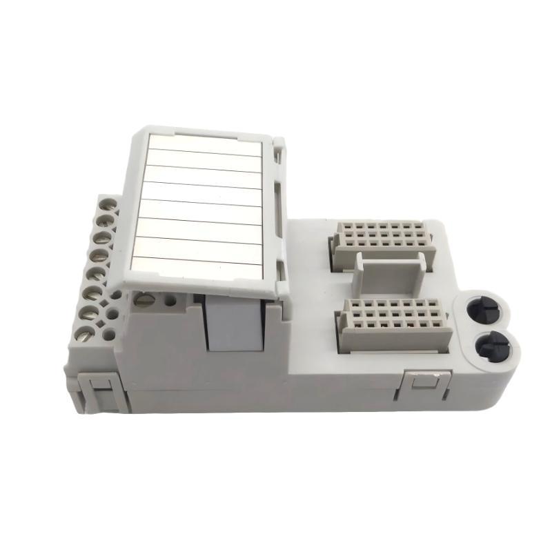
1. Product Overview
The GE 8610-FT-NA is a non-arcing field terminal designed for industrial I/O applications where field wiring must be connected to compatible control system modules. It provides a structured termination point between field devices and the control system, helping organize signal wiring and simplify installation, inspection, and maintenance. The 8610-FT-NA belongs to the 8000 Series field terminal family. Its non-arcing designation makes it suitable for specified Class I, Division 2 or Zone 2 applications when used as part of an approved system configuration. It is important to distinguish this type of protection from intrinsic safety: the 8610-FT-NA is not an intrinsically safe field terminal and must not be substituted for an IS terminal where intrinsic safety is required. The terminal is intended for use with compatible I/O modules and their associated installation arrangements. Correct selection depends on the I/O module type, field circuit characteristics, wiring method, and hazardous-area classification. This guide covers preparation, mounting, field wiring, commissioning, and maintenance considerations for the GE 8610-FT-NA.
2. Technical Specifications
The following table summarizes the commonly listed specifications for the 8610-FT-NA field terminal.
| Parameter | Specification |
|---|---|
| Manufacturer / Product Family | GE / 8000 Series |
| Model | 8610-FT-NA |
| Product Type | Non-Arcing Field Terminal |
| Application | Industrial I/O field wiring termination |
| Hazardous-Area Application | Specified Class I, Division 2 or Zone 2 installations, subject to system approval |
| Rated Voltage | 250 VAC |
| Maximum Current per I/O Channel | 3 A |
| Fuse | Unfused terminal type |
| Supported Conductor Size | 0.14–2.5 mm² |
| Material | Modified polyphenylene oxide |
| Approximate Dimensions | 42 × 88 × 39.5 mm |
| Typical Weight | Approximately 78 g, including tagging strip |
| Connection Method | Screw-clamp field wiring termination |
These values should be checked against the exact product revision and the applicable I/O module documentation before installation. The 250 VAC rating and 3 A maximum channel current are component limits, not permission to operate every connected circuit at those values. The complete system must comply with the ratings of the I/O module, field device, wiring, and protective equipment.
3. Main Functions of the 8610-FT-NA
3.1 Field Signal Termination
The 8610-FT-NA provides a termination point for field wiring. Field conductors from sensors, switches, actuators, or other devices can be connected through the designated terminal positions and routed into the associated I/O system. A well-organized termination arrangement makes it easier to identify individual signal circuits and reduces the likelihood of wiring errors during installation or maintenance.
3.2 Non-Arcing Field Wiring Arrangement
The 8610-FT-NA is identified as a non-arcing field terminal for specified hazardous-area applications. Its suitability depends on the complete installation, including the compatible I/O module, field circuit, enclosure, wiring practices, and applicable certification conditions. The non-arcing designation must not be interpreted as universal hazardous-area approval. Engineers should confirm the permitted area classification and installation conditions for the complete equipment assembly.
3.3 Organized Maintenance and Identification
The field terminal family uses a tagging strip to support circuit identification. Clear labeling helps maintenance personnel trace field wiring, identify individual channels, and reduce the time required for troubleshooting. Recommended labeling information includes the instrument tag, I/O channel, signal description, and terminal reference used in the approved wiring drawing.
4. Installation Preparation
4.1 Verify the Product Model
Before installation, confirm that the terminal is marked 8610-FT-NA. Do not confuse it with other 8000 Series field terminals. For example, the 8611-FT-FU is a fused non-arcing field terminal, while the 8610-FT-NA is the standard non-arcing version. Other models are designed for different wiring or signal applications. Check the following before proceeding:
- Complete model number and product identification.
- Physical condition of the terminal housing.
- Condition of screw-clamp connections.
- Tagging strip and identification markings.
- Compatibility with the selected I/O module.
- Suitability for the installation area’s classification.
4.2 Confirm I/O Module Compatibility
The 8610-FT-NA is not a universal terminal for every I/O module. The receiving module must explicitly list the 8610-FT-NA as a recommended or compatible field terminal. Check the module’s installation drawing for the correct terminal type, channel arrangement, and wiring diagram. The electrical characteristics of the field signal must also match the module’s input or output requirements.
4.3 Prepare Tools and Materials
Typical installation tools and materials include:
- Insulated screwdrivers suitable for the terminal screws.
- Wire preparation and stripping tools.
- Appropriately rated multimeter.
- Approved field wiring and cable identification labels.
- Required mounting hardware and accessories.
- ESD protection where electronic assemblies are handled.
Use the conductor type and wire preparation method specified by the equipment documentation. Avoid damaged, frayed, or incorrectly stripped conductors.
5. Safety Precautions
Installation should be carried out by qualified industrial electrical and automation personnel. Before connecting or removing field wiring:
- Review the electrical drawings and hazardous-area installation requirements.
- Isolate the relevant power sources and apply lockout/tagout procedures.
- Verify that the circuits are de-energized before handling conductors.
- Check whether external field devices can introduce voltage into the wiring.
- Use suitable tools and personal protective equipment.
- Keep the terminal free from moisture, conductive dust, and metal debris.
- Do not exceed the terminal’s electrical ratings or the lower ratings of connected equipment.
For Class I, Division 2 or Zone 2 applications, follow the exact conditions specified by the system certification and installation documentation. Do not disconnect field wiring while energized unless the complete installation documentation and applicable regulations explicitly permit it. The 8610-FT-NA is a non-arcing terminal, not an intrinsically safe barrier. It must not be used as a substitute for an intrinsically safe field terminal or associated apparatus.
6. GE 8610-FT-NA Installation Procedure
Step 1: Inspect the Installation Location
Check the designated mounting position and surrounding equipment. Confirm that the terminal can be installed in the intended carrier or field termination arrangement. Inspect for mechanical damage, contamination, loose components, or damaged connectors. The mounting area should provide adequate space for wiring access and maintenance.
Step 2: Confirm the Terminal Arrangement
Review the installation drawing for the associated I/O module. Confirm that the selected terminal type is 8610-FT-NA and that its connection arrangement matches the intended field circuits. Do not rely on terminal position or physical appearance to identify signal assignments. Use the correct module-specific wiring diagram.
Step 3: Mount the Field Terminal
Position the 8610-FT-NA in its designated mounting location and secure it using the specified hardware or retention arrangement. Make sure that the terminal is correctly aligned and mechanically stable. Avoid excessive force, which may damage the housing or connection components.
Step 4: Prepare the Field Conductors
Prepare each field conductor according to the wiring specification. The listed conductor size range is 0.14–2.5 mm². Strip the insulation to the required length without damaging the conductor strands. If ferrules or other conductor termination accessories are required by the project standard, use the correct type and size. Label the conductors before connecting them. This is particularly important in systems with multiple similar sensors or field devices.
Step 5: Connect the Field Wiring
Connect each conductor to the correct terminal position using the module-specific wiring diagram. Check the following:
- Correct channel assignment.
- Correct signal polarity where applicable.
- Correct common or return connection.
- Correct conductor size and preparation.
- Secure screw-clamp connections.
- No exposed conductor strands outside the terminal.
Do not invent or assume a universal pinout for the 8610-FT-NA. Exact terminal assignments depend on the associated I/O module and its wiring configuration.
Step 6: Connect the Associated I/O Equipment
Complete the connection between the field terminal and its designated I/O equipment according to the system installation drawing. Verify that the field terminal, I/O module, and carrier arrangement are compatible. Check that the module is installed in the correct position and that all mechanical connections are properly engaged.
Step 7: Complete a Wiring Inspection
Before restoring power, inspect all connected conductors and terminal points. Confirm that:
- Every conductor is connected to the intended position.
- No wires are loose or incorrectly routed.
- There are no short circuits between adjacent terminals.
- Field cable shields and grounding connections follow the project design.
- All identification labels match the wiring drawings.
- The terminal and surrounding equipment are free of foreign objects.
7. Commissioning and Functional Verification
7.1 Pre-Power Checks
Before energizing the associated I/O equipment, verify that the installation is complete and that all field circuits have been checked. Review the module configuration, field device type, wiring polarity, and hazardous-area requirements. Confirm that the connected circuit voltage and current remain within the permitted ratings.
7.2 Restore Power
Restore power according to the approved commissioning procedure. Observe the I/O module and associated control equipment for abnormal indications. If unexpected alarms or abnormal behavior appear, stop the commissioning process and investigate the wiring and module configuration before continuing.
7.3 Verify Individual Channels
Test each connected field circuit using the approved functional test procedure for the associated I/O module. For digital input applications, operate the field switch or sensor and confirm that the corresponding channel changes state correctly. For analog input or output applications, use the specified signal source or test method and compare the measured response with the expected module behavior. Do not apply a test signal simply because the terminal can physically accept the conductor. The signal type and electrical range must be compatible with the I/O module.
7.4 Confirm Control System Response
Check the controller diagnostics, I/O channel status, and operator interface. Confirm that the field signal is correctly recognized and that the control system responds as expected. Any discrepancy between the field device and the controller should be investigated before the system is returned to normal operation.
7.5 Document Commissioning Results
Record the following information:
- Field terminal model and identification.
- Associated I/O module model.
- Field device and channel assignments.
- Wiring inspection results.
- Functional test results.
- Hazardous-area installation verification where applicable.
- Outstanding alarms or corrective actions.
8. Industrial Applications
8.1 Process Automation
In process automation installations, field terminals provide organized connections between instruments and control system I/O modules. The 8610-FT-NA can be used in compatible non-arcing field wiring arrangements where its ratings and approval conditions match the application.
8.2 Manufacturing and Production Lines
Manufacturing facilities use field wiring terminals to connect sensors, switches, and other field devices to distributed control and monitoring equipment. Clear channel identification helps simplify commissioning and maintenance.
8.3 Distributed I/O Systems
In distributed I/O architectures, field terminals help organize wiring close to the I/O equipment. This can improve cable management and make individual signal circuits easier to inspect.
8.4 Specified Zone 2 and Division 2 Installations
The non-arcing design is intended for specified hazardous-area applications. Before use, engineers must verify the complete system’s certification, installation conditions, and compatibility with the field circuit.
9. Maintenance and Inspection Recommendations
Periodic inspection helps maintain reliable field connections and identify developing wiring problems. Recommended maintenance activities include:
| Inspection Item | Recommended Action | Purpose |
|---|---|---|
| Terminal housing | Check for cracks, deformation, or contamination | Identify mechanical damage |
| Screw-clamp connections | Inspect under safe, de-energized conditions | Prevent loose connections |
| Field conductors | Check insulation, conductor preparation, and routing | Reduce wiring faults |
| Identification labels | Confirm that labels remain readable and accurate | Support maintenance and fault tracing |
| Channel operation | Perform functional checks when required | Verify signal transmission |
| Environmental condition | Check for moisture, dust, and corrosive contamination | Protect electrical connections |
Do not tighten terminal screws indiscriminately. Use the specified torque and maintenance procedure for the particular terminal assembly.
10. Frequently Asked Questions
What is the GE 8610-FT-NA?
The 8610-FT-NA is a non-arcing field terminal in the 8000 Series family. It provides field wiring termination for compatible industrial I/O applications.
Is the 8610-FT-NA a fused field terminal?
No. The 8610-FT-NA is the standard non-arcing version. The 8611-FT-FU is a separate fused non-arcing field terminal model.
What is the rated voltage of the 8610-FT-NA?
Its commonly listed rated voltage is 250 VAC, with a maximum current of 3 A per I/O channel. The actual operating limits must also comply with the associated I/O module and complete system ratings.
What wire size does the 8610-FT-NA support?
The listed conductor size range is 0.14–2.5 mm². Confirm conductor preparation and any ferrule requirements against the installation documentation.
Can the 8610-FT-NA be used in hazardous areas?
It is identified as a non-arcing field terminal for specified Class I, Division 2 or Zone 2 applications. Its use is subject to the approval conditions and installation requirements of the complete system.
Is the 8610-FT-NA an intrinsically safe terminal?
No. Non-arcing and intrinsically safe are different protection concepts. Use an approved intrinsically safe field terminal and associated equipment when the application requires an IS circuit.
Can the 8610-FT-NA be used with any 8000 Series I/O module?
No. Compatibility depends on the I/O module and its installation documentation. Confirm that the module specifically recommends or permits the 8610-FT-NA before installation.
10. Conclusion
The GE 8610-FT-NA Field Terminal is a non-arcing field wiring component designed for compatible industrial I/O systems. Its screw-clamp termination arrangement, compact construction, and channel identification features support organized field wiring and routine maintenance. Successful installation requires more than matching the terminal model. Engineers must verify I/O module compatibility, field circuit ratings, conductor preparation, wiring assignments, and hazardous-area requirements. Careful commissioning and periodic inspection help maintain reliable signal connections and reduce avoidable maintenance problems.
Technical Summary
The 8610-FT-NA is a standard non-arcing field terminal with a listed 250 VAC rating, a maximum current of 3 A per I/O channel, and a conductor size range of 0.14–2.5 mm². It is intended for use with compatible 8000 Series I/O equipment. Always confirm the exact module wiring diagram and system approval conditions before installation or commissioning.