

ProductPRODUCT
Featured products
Contact Us
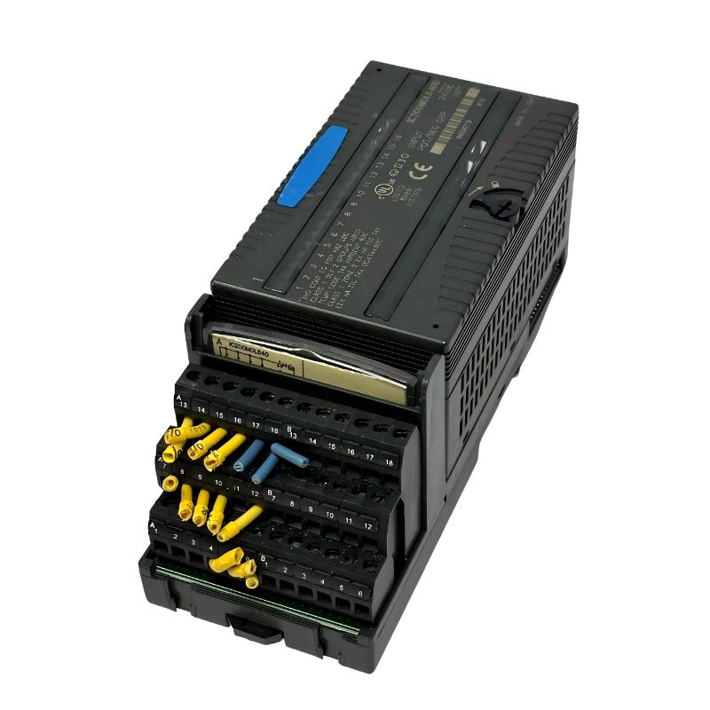
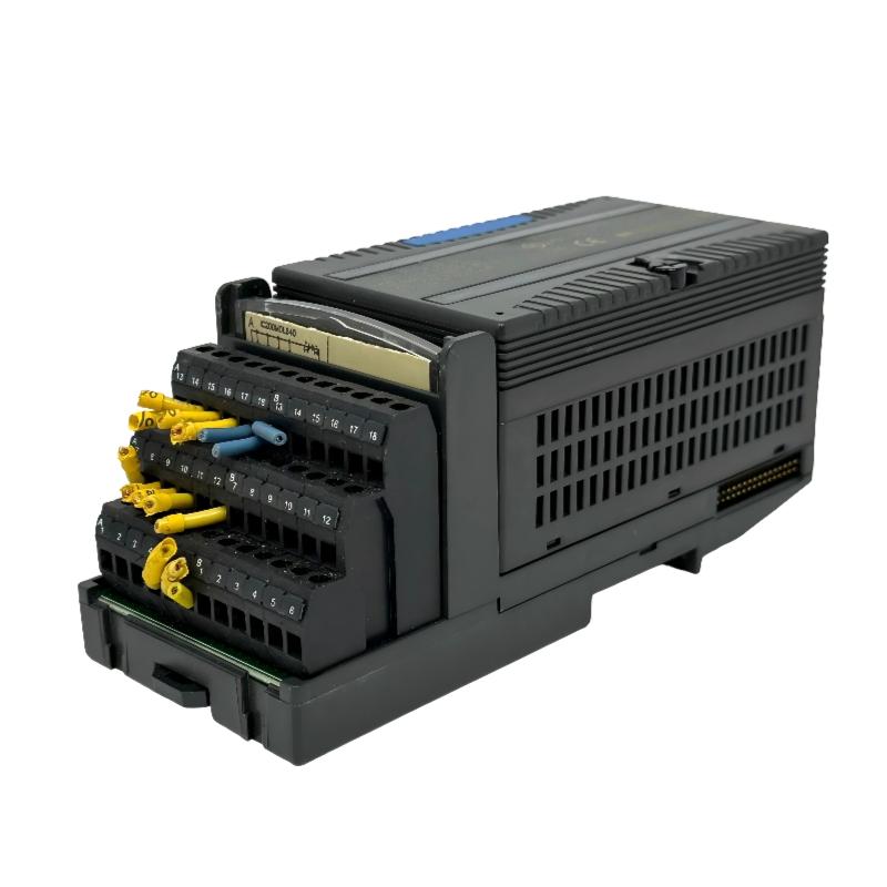
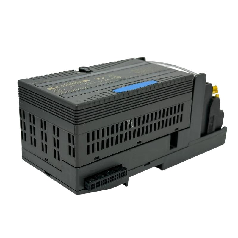
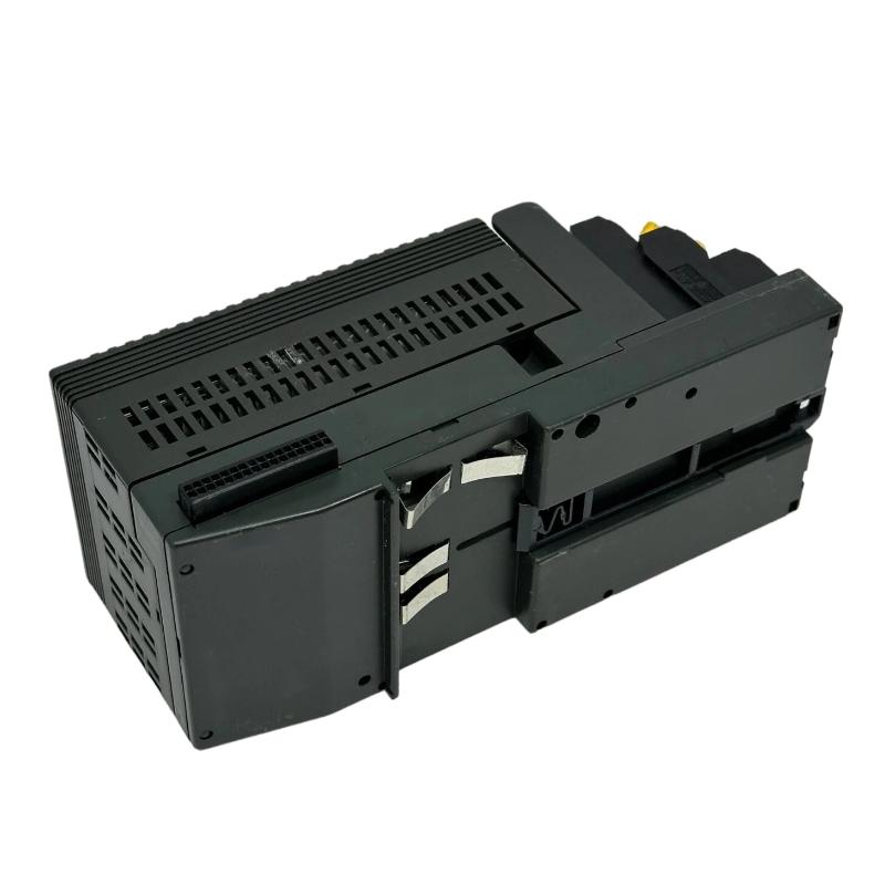
- GE
- IC200MDL640D
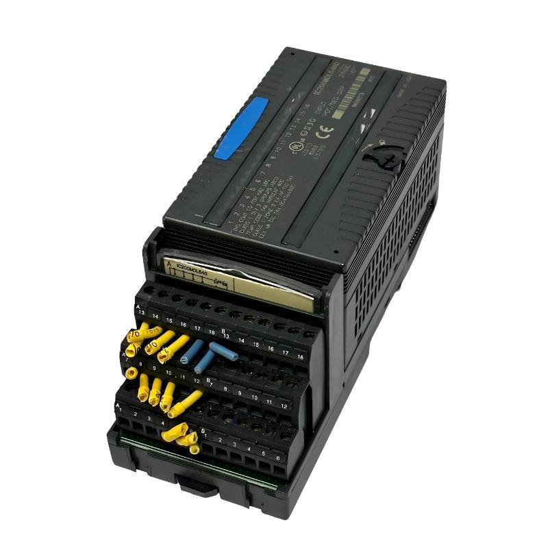
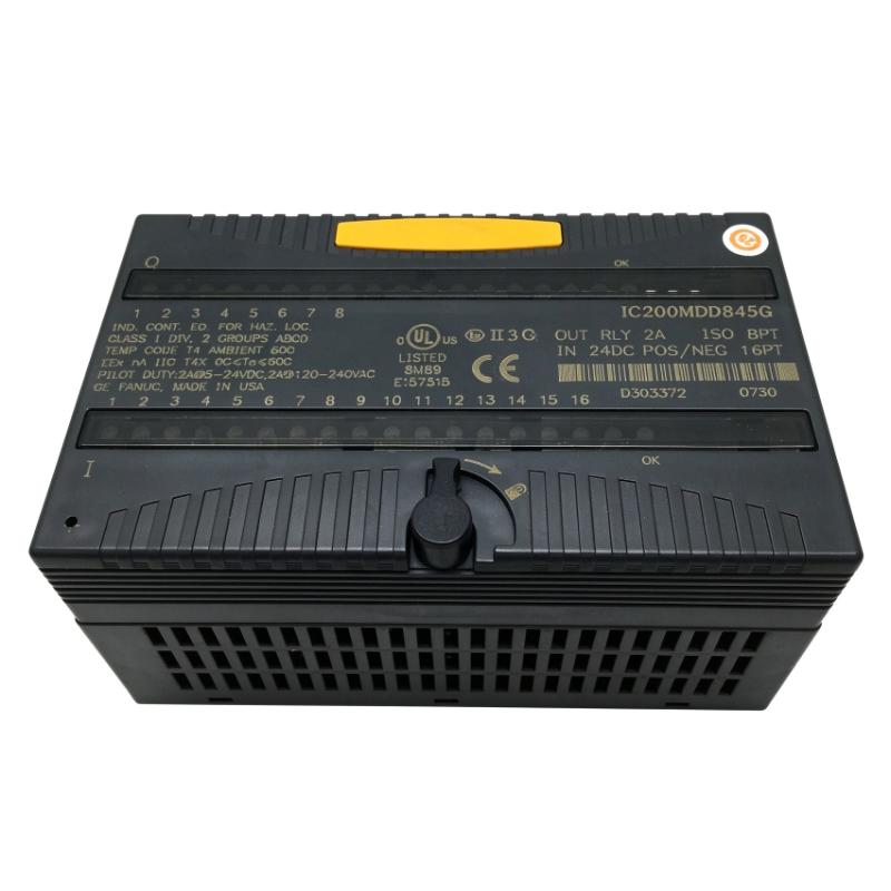
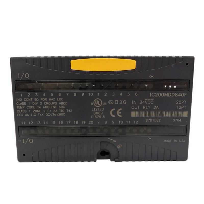
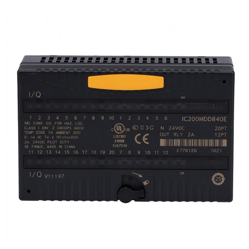
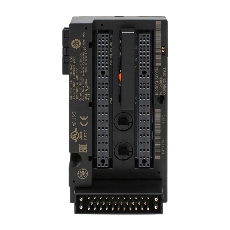
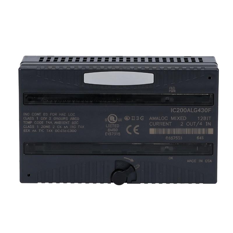
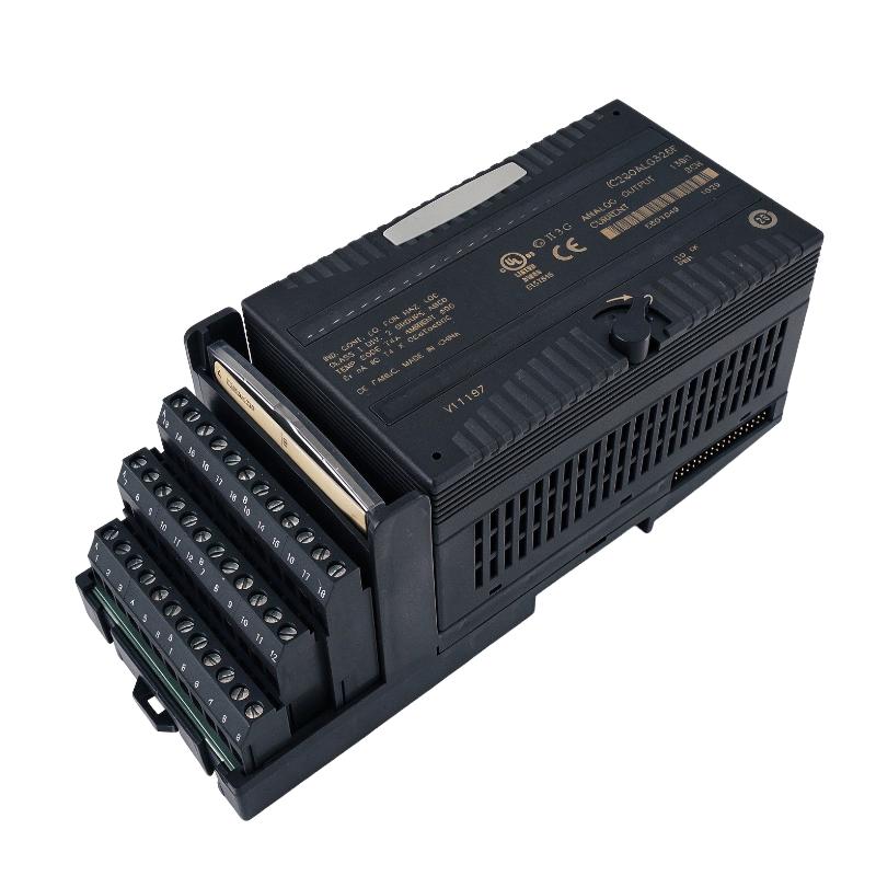
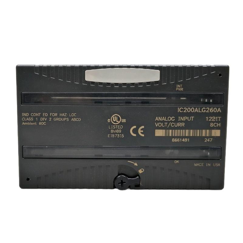
- VersaMax Discrete Input Module
- USA
- 110 x 66.8 x 50 mm
- 0.45 kg
- Xiamen, China
- New & In Stock
- T/T, PayPal, Western Union
- 1 Year
- 1-3 Working Days
- DHL, UPS, TNT, FedEx and EMS.
- 24-Hour Service
- COO
- 7
Our advantage

Global Logistics
We have a 10-year logistics and express cooperation agreement, so our products can be shipped to any place in the world.

Brand new and original
Our products are imported in bulk from the place of origin. Because of the cooperative relationship, our products are all original and 100% new.

24-hour service
We provide 7*24 hours service to our customers. We will be there whenever you need us.

Price advantage
All our products are priced very favorably because we have our own warehouse and supply.
| Company Information | |||
| [email protected] | |||
| Mobile | +8615980777398 | ||
| +8615980777398 | |||
| 15980777398 |
Product Overview
The GE IC200MDL640D VersaMax Discrete Input Module is an industrial digital input module designed for the GE Fanuc VersaMax programmable logic controller and distributed I/O platform. It provides an interface between field-level switching devices and the PLC control system, allowing the controller to monitor discrete operating conditions and respond to changes in the production process.
Discrete input modules are essential components in industrial automation. They receive two-state signals from devices such as proximity sensors, limit switches, pushbuttons, selector switches, and other field instruments. These signals represent conditions such as ON or OFF, open or closed, and activated or inactive.
The IC200MDL640D provides 16 discrete input points and supports 24 V DC positive or negative logic. Its inputs are divided into two groups of eight, with a common connection for each group. This arrangement gives engineers flexibility when connecting compatible field devices to a VersaMax control system.
The module is designed for applications that require reliable acquisition of digital field signals. It works with a compatible VersaMax carrier base and communicates input status to the controller through the system backplane. Individual LED indicators provide visual information about input states, while an OK indicator helps show whether backplane power is present.
The IC200MDL640D is suitable for industrial equipment monitoring, machine control, production-line automation, and distributed I/O installations. Its compact form allows it to be installed alongside other VersaMax modules in a modular control architecture.
When selecting this module for maintenance or replacement, it is important to verify the complete part number and hardware revision. Input voltage, point count, wiring logic, carrier compatibility, and terminal configuration should all be checked before installation.
Technical Specifications
| Parameter | Specification |
|---|---|
| Brand | GE Fanuc / GE |
| Product Series | VersaMax |
| Model | IC200MDL640D |
| Product Type | Discrete Input Module |
| Module Function | Digital Signal Acquisition |
| Number of Input Points | 16 |
| Input Voltage Range | 0–30 V DC |
| Nominal Input Voltage | 24 V DC |
| Input Logic | Positive / Negative Logic |
| Input Groups | 2 groups of 8 |
| Input Isolation | Optical isolation between field inputs and logic |
| Point-to-Point Isolation | None |
| Basic Input Response Time | 0.5 ms maximum |
| Input ON-State Voltage | +15 to +30 V DC |
| Input OFF-State Voltage | 0 to +5 V DC |
| ON-State Current | 2.0–5.5 mA |
| OFF-State Current | 0–0.5 mA |
| Input Impedance | 10 kΩ maximum |
| Backplane Current Consumption | 25 mA maximum at 5 V DC |
| External Power Supply | Not required for module logic |
| LED Indicators | Individual input LEDs and OK LED |
| Mounting | Compatible VersaMax carrier base |
| Dimensions Provided | 110 × 66.8 × 50 mm |
| Weight Provided | 0.45 kg |
| Typical Application | PLC digital input monitoring |
Dimensions are for the module itself and do not include the carrier base or mating connectors. Confirm the physical assembly dimensions when planning cabinet space.
Function and Working Principle
The main function of the IC200MDL640D is to receive discrete electrical signals from field devices and make their status available to the VersaMax controller.
The module converts the electrical state of each input circuit into digital information that can be processed by the PLC program.
1. Digital Input Signal Acquisition
Industrial sensors and switches generate signals according to equipment conditions. For example, a limit switch may change state when a mechanical component reaches a specific position. A proximity sensor may indicate whether a metal object is present.
The IC200MDL640D receives compatible 24 V DC signals through its input terminals. Each input point corresponds to a separate digital status that can be monitored by the controller.
This allows the PLC to identify equipment conditions and execute programmed actions.
2. Positive and Negative Logic
The module supports positive and negative logic input arrangements.
In positive logic wiring, the input device supplies current to the module input when activated. In negative logic wiring, the common connection supplies current to the field device, and the device returns current to the input point.
The two input groups have separate common connections. Each group contains eight input points and can be wired according to the selected logic arrangement.
This flexibility is useful when integrating different field-device wiring configurations into one control system.
Negative-logic functionality requires an appropriate module revision. Confirm the hardware revision and manufacturer’s documentation before using this wiring mode.
3. Optical Isolation
The input circuitry provides optical isolation between the field input circuits and the module’s internal logic.
Optical isolation helps reduce the direct transfer of electrical disturbances from field wiring into the controller’s logic circuitry. This is important in industrial environments where motors, contactors, solenoids, and switching equipment may generate electrical interference.
The module does not provide point-to-point isolation between individual input channels. Engineers should consider this when designing field wiring and connecting devices with different electrical references.
4. Input Status Indication
The module provides an LED for each input point. These indicators allow maintenance personnel to observe the ON or OFF status of individual field signals.
An additional OK LED indicates the presence of backplane power.
LED status can help technicians distinguish between an inactive field device, a wiring issue, and a module or backplane power problem. However, LED indications should be interpreted together with PLC diagnostics and electrical measurements.
5. Response Time and Input Filtering
The basic input ON/OFF response time is approximately 0.5 ms maximum.
The module also supports configurable input filtering. Depending on the application, filtering can help reduce the effects of electrical noise or contact bounce. The documented filter choices include 0 ms, 1.0 ms, and 7.0 ms.
The selected filter setting affects the total response time. Applications that require fast signal detection should consider the relationship between filtering and response speed.
Role in Industrial Control Systems
The IC200MDL640D is an input-side component in a PLC automation system. It collects field information and transfers the resulting digital status to the controller.
PLC Signal Processing
A VersaMax CPU or network interface unit processes the input information according to the control program.
For example, when a sensor detects a product, the module reports the input state. The PLC program can then activate an output module, update a production counter, or initiate another machine sequence.
Machine Condition Monitoring
The module can monitor discrete machine conditions such as:
- Motor auxiliary contact status.
- Emergency-stop circuit status through an appropriate safety architecture.
- Limit-switch activation.
- Product detection.
- Valve position feedback.
- Door and guard switch status.
- Equipment running or stopped signals.
The IC200MDL640D itself is a standard digital input module, not a safety-rated input device. Safety-related functions must use appropriately certified safety equipment and circuit designs.
Distributed I/O Architecture
VersaMax systems support modular and distributed I/O arrangements. The IC200MDL640D can be installed with other compatible modules to collect different types of field signals.
This modular structure allows control-system designers to organize digital inputs, digital outputs, analog signals, and other functions according to the requirements of the machine or production process.
Maintenance Diagnostics
The individual input LEDs provide a convenient first-level diagnostic tool. Technicians can compare the physical LED state with the actual condition of a field device and the corresponding PLC variable.
If a signal does not appear correctly in the controller, possible causes include field-device failure, incorrect wiring, an unsuitable common connection, a carrier-base problem, or an incorrect configuration.
Industrial Applications
1. Manufacturing Automation
Manufacturing equipment uses numerous digital signals to monitor machine conditions and coordinate production sequences.
The IC200MDL640D can collect signals from sensors, pushbuttons, and limit switches. The PLC uses these signals to control machine movement, manage production stages, and detect abnormal operating conditions.
2. Conveyor and Material Handling Systems
Conveyor systems rely on discrete sensors to detect products, monitor transfer positions, and confirm equipment status.
The module can receive signals from photoelectric sensors, proximity switches, and mechanical limit switches. The PLC can use this information to coordinate conveyors and manage product movement.
3. Packaging Machinery
Packaging equipment uses digital inputs to monitor material presence, package position, machine doors, and cycle conditions.
The 16 input points allow several field signals to be collected through a single module. This can help organize machine-control wiring and provide the PLC with the information required for sequence control.
4. Pumping and Auxiliary Equipment
Industrial pumping systems may use digital signals to indicate motor status, valve position, pressure-switch activation, and equipment interlocks.
The module can collect compatible 24 V DC signals from these devices and transfer their status to the PLC for monitoring and control.
5. Process Automation
Process plants use discrete signals alongside analog measurements to monitor equipment and operating conditions.
The IC200MDL640D can be used for status monitoring of auxiliary machinery, valve limit switches, local control stations, and other binary field devices.
6. Industrial Equipment Retrofitting
In existing VersaMax installations, the module may be used as a replacement component when an original input module requires maintenance.
Before replacement, engineers should confirm the exact model, hardware revision, input logic requirements, carrier compatibility, and existing wiring arrangement.
Installation and System Integration
Correct installation is necessary for reliable signal acquisition and stable PLC operation.
1. Verify Carrier Base Compatibility
The IC200MDL640D requires a compatible VersaMax carrier base. The module should not be treated as a standalone controller or terminal assembly.
Before installation, verify the carrier model, mechanical fit, connector condition, and mounting arrangement.
2. Confirm Field Signal Voltage
The module is designed for 24 V DC nominal input signals within a 0–30 V DC range.
Check the field-device output voltage before connecting it to the input terminals. Signals outside the permitted range may cause incorrect operation or damage.
3. Plan the Input Groups
The 16 input points are divided into two groups of eight. Each group has its own common terminal.
The wiring plan should identify which field devices belong to each group and whether positive or negative logic is required.
Do not assume that all channels have independent commons. The grouping arrangement must be considered when designing the field wiring.
4. Connect Field Devices
Typical field devices include proximity sensors, photoelectric sensors, pushbuttons, and limit switches.
Use suitable industrial wiring practices, maintain secure terminal connections, and route signal cables appropriately to reduce electrical interference.
5. Configure Input Filtering
Input filtering should be selected according to the characteristics of the field devices and the required response time.
A longer filter can help reduce false transitions caused by electrical noise or mechanical contact bounce. However, it also increases the time required for a signal change to be recognized.
6. Verify LED and PLC Status
After wiring, verify that each field device produces the expected input LED indication.
Then check the corresponding PLC input variables and confirm that the control program responds correctly. Test each input point individually where practical.
7. Observe Electrical Safety Requirements
Before removing or installing the module, follow the manufacturer’s instructions and the site’s electrical isolation procedures.
For hazardous locations, follow the applicable equipment certification and installation requirements. Do not remove or connect the module while energized unless the system documentation explicitly permits the operation.
Compatible System Components
The IC200MDL640D is designed to work within a compatible VersaMax I/O system.
| Component | Function | Integration Consideration |
|---|---|---|
| VersaMax CPU | Executes PLC logic | Must support the installed VersaMax I/O architecture |
| Network Interface Unit | Connects distributed I/O to a control network | Confirm the network interface and system configuration |
| VersaMax Carrier Base | Provides the module mounting and electrical connection | Required for module installation |
| 24 V DC Sensors | Generate field input signals | Verify voltage and output type |
| Limit Switches | Detect mechanical positions | Confirm contact arrangement and wiring logic |
| Pushbuttons | Provide operator input | Use appropriate contact and voltage ratings |
| Photoelectric Sensors | Detect objects and product presence | Verify output polarity and current requirements |
| Proximity Sensors | Detect nearby objects without contact | Confirm 24 V DC compatibility |
| VersaMax Power Supply | Supplies the control system | Verify backplane and system power requirements |
| Digital Output Module | Controls actuators and other devices | Coordinates with PLC logic and input feedback |
The listed components are examples of equipment that may be used in a VersaMax system. They are not necessarily supplied with the IC200MDL640D.
Alternative Models and Replacement Considerations
When replacing the IC200MDL640D, the most important factors are input voltage, point count, logic arrangement, carrier compatibility, and hardware revision.
| Model | Product Description | Replacement Consideration |
|---|---|---|
| IC200MDL640 | VersaMax 24 V DC, 16-point discrete input module | Base model in the same input family; verify revision and specifications |
| IC200MDL650 | VersaMax 24 V DC, 32-point discrete input module | Higher point count with a different channel arrangement |
| IC200MDL643 | VersaMax 5/12 V DC TTL input module | Different input voltage range; not a direct substitute |
| IC200MDL644 | VersaMax 5/12 V DC TTL, 32-point input module | Different voltage and point count |
| IC200MDL631 | VersaMax 125 V DC isolated input module | Different electrical input requirements |
| IC200MDL635 | VersaMax 48 V DC grouped input module | Requires a different field-signal voltage |
A replacement should not be selected solely because it belongs to the VersaMax family. Verify the input characteristics and terminal arrangement before connecting existing field wiring.
Key Advantages
16 Discrete Input Points
The module provides 16 digital input channels for collecting field signals from sensors, switches, and operator devices.
24 V DC Input Compatibility
Its 24 V DC nominal input rating supports common industrial control signals.
Positive and Negative Logic Support
The module supports positive and negative logic arrangements, providing flexibility for compatible field-device wiring.
Two Groups of Eight Inputs
The grouped input structure provides a defined common connection for each set of eight channels.
Individual LED Indicators
Point-level LEDs help maintenance personnel identify input status during troubleshooting.
Fast Basic Response
The basic input response time of approximately 0.5 ms supports applications requiring relatively fast recognition of discrete signal changes.
Compact VersaMax Design
Its compact form supports modular installation in compatible VersaMax carrier systems.
Optical Isolation
Optical isolation between field input circuits and internal logic helps reduce the direct transfer of electrical disturbances into the control system.
Technical FAQs
1. What is the GE IC200MDL640D?
The IC200MDL640D is a VersaMax discrete input module designed to receive 24 V DC digital signals from industrial field devices and transfer their status to a compatible PLC system.
2. How many input points does it provide?
It provides 16 discrete input points, arranged in two groups of eight.
3. What is its input voltage?
The module supports a 0–30 V DC input range, with 24 V DC as the nominal input voltage.
4. Does it support positive and negative logic?
Yes. It supports positive and negative logic wiring. Each group of eight inputs has a common connection.
5. What is the input response time?
The basic input ON/OFF response time is approximately 0.5 ms maximum. Configurable filtering can increase the total response time.
6. Does the module require an external power supply?
The module’s internal operation receives power through the VersaMax backplane. The field input signals are supplied by compatible field circuits.
7. Does it provide channel-to-channel isolation?
No. The module does not provide point-to-point isolation between individual input channels. Its isolation characteristics should be considered when designing field wiring.
8. What does the OK LED indicate?
The OK LED indicates that backplane power is present at the module. Individual input LEDs show the ON/OFF status of their corresponding channels.
9. Does the IC200MDL640D require a carrier base?
Yes. It requires a compatible VersaMax carrier base for mechanical installation and electrical connection.
10. Can the IC200MDL650 replace it?
Not as a direct plug-in replacement without engineering verification. The IC200MDL650 has 32 input points rather than 16 and uses a different input grouping arrangement. Check the wiring, configuration, and carrier requirements before considering substitution.
Procurement and Maintenance Recommendations
When purchasing the GE IC200MDL640D, verify the complete part number and hardware revision. The suffix is important because different revisions may have changes in hardware design or supported functions.
For replacement projects, compare the original module’s input voltage, point count, positive or negative logic requirements, and terminal wiring with the replacement unit. Confirm the carrier base model and inspect the connector condition before installation.
For used or surplus modules, request clear photographs of the front label, terminal area, and connector. Check the housing, locking mechanism, and terminal condition. Where the module is intended for critical production equipment, request suitable functional testing before returning it to service.
During routine maintenance, inspect field wiring and terminal connections. Check the input LEDs and compare their states with the connected sensors and PLC variables. If a signal is missing or unstable, investigate the field device, wiring, common connection, carrier base, and PLC configuration before assuming that the input module has failed.
Keep a record of the module’s part number, revision, installation location, and associated PLC configuration. This information can simplify future maintenance and reduce errors during replacement.
Conclusion
The GE IC200MDL640D VersaMax Discrete Input Module is a 16-point digital input component designed for 24 V DC industrial signal acquisition. It supports positive and negative logic wiring, uses two groups of eight inputs, and provides individual LED indicators for input monitoring.
With its compact modular design and compatibility with the VersaMax I/O architecture, the IC200MDL640D can support machine automation, process monitoring, material handling, and other industrial control applications.
For procurement and replacement, engineers should verify the complete model number, hardware revision, carrier compatibility, input voltage, and wiring configuration. Correct installation and maintenance help ensure reliable communication between field devices and the PLC control system.