

ProductPRODUCT
Featured products
Contact Us
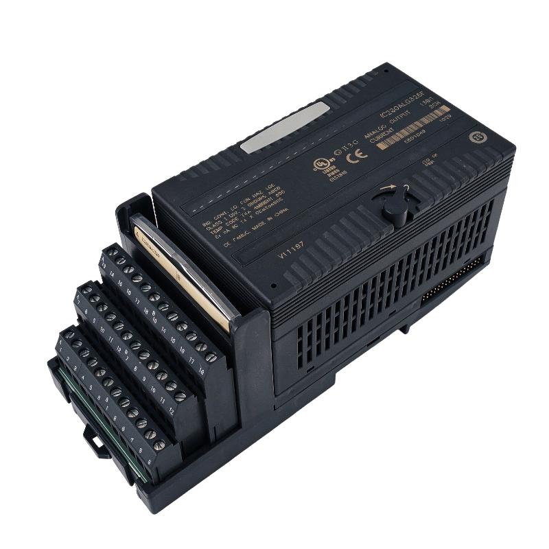
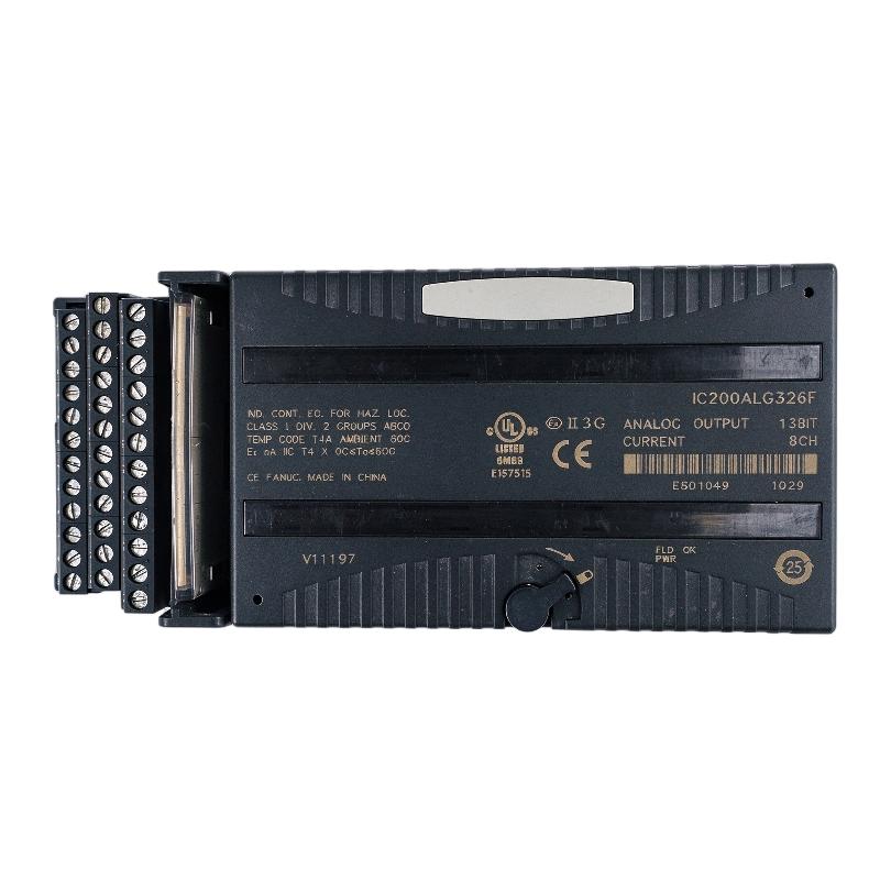
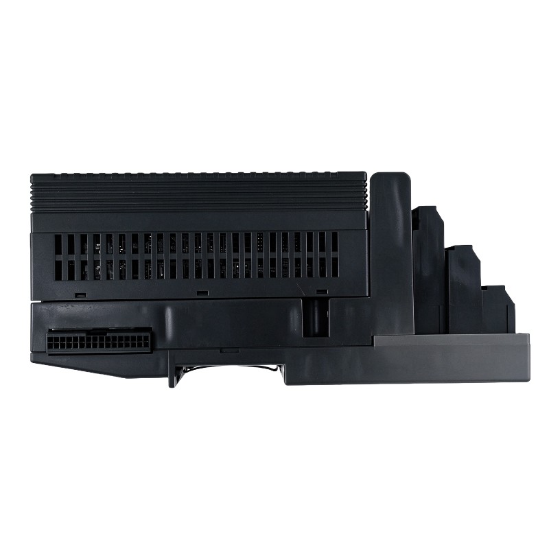
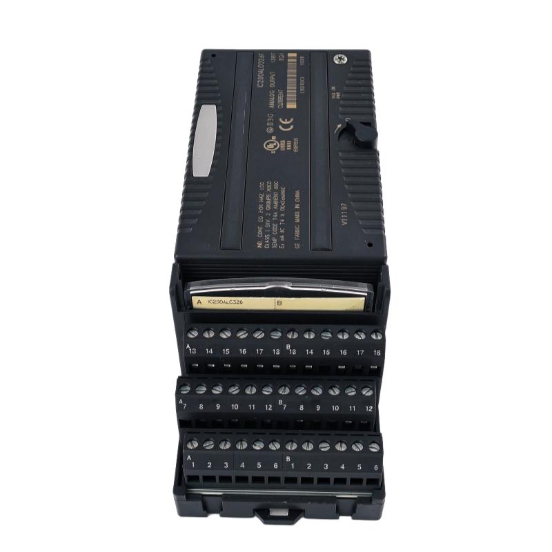
- GE
- IC200ALG326F
- Analog Output Module
- USA
- 110 x 66.8 x 50 mm
- 0.19 kg
- Xiamen, China
- New & In Stock
- T/T, PayPal, Western Union
- 1 Year
- 1-3 Working Days
- DHL, UPS, TNT, FedEx and EMS.
- 24-Hour Service
- COO
- 9
Our advantage

Global Logistics
We have a 10-year logistics and express cooperation agreement, so our products can be shipped to any place in the world.

Brand new and original
Our products are imported in bulk from the place of origin. Because of the cooperative relationship, our products are all original and 100% new.

24-hour service
We provide 7*24 hours service to our customers. We will be there whenever you need us.

Price advantage
All our products are priced very favorably because we have our own warehouse and supply.
| Company Information | |||
| [email protected] | |||
| Mobile | +8615980777398 | ||
| +8615980777398 | |||
| 15980777398 |
Product Overview
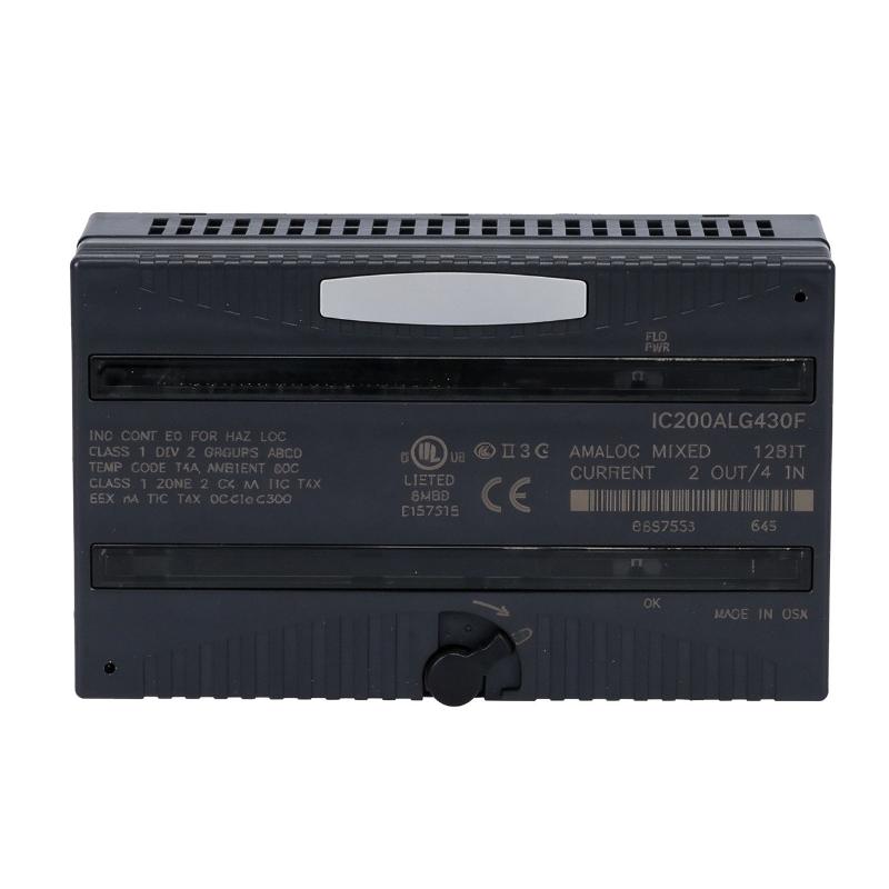
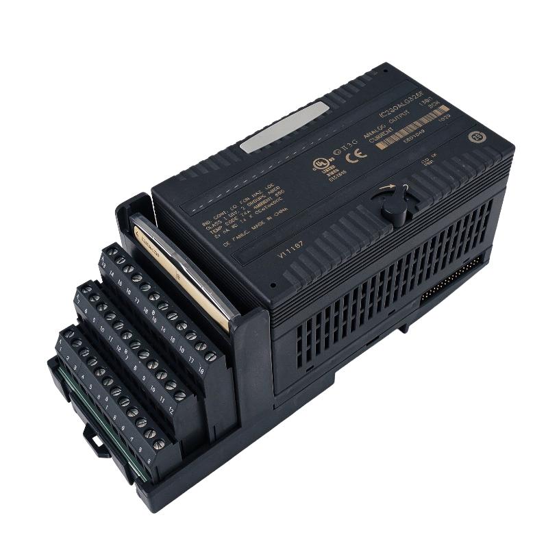
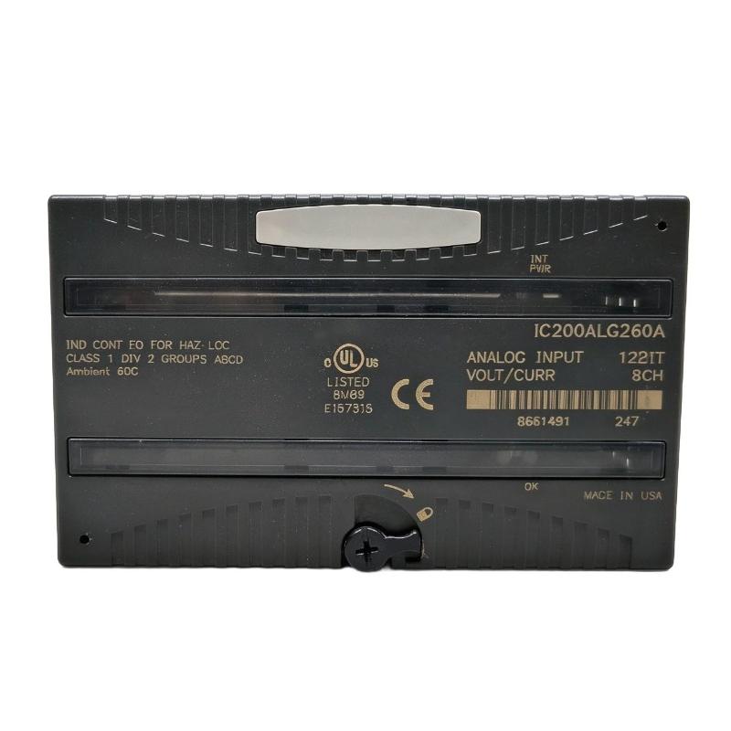
The GE IC200ALG326F VersaMax Analog Output Module is an industrial programmable logic controller (PLC) output module designed to convert digital control data into analog current signals. It belongs to the GE Fanuc VersaMax distributed I/O product family and is used in automation systems that require accurate current-based control of field devices.
Analog output modules are important components in industrial control systems because many process instruments and actuators require continuous analog signals rather than simple ON/OFF commands. Examples include control valve positioners, variable frequency drives, pressure regulators, and other equipment that accepts current references from a PLC.
The IC200ALG326F provides eight single-ended current-sourcing output channels arranged in one group. Each channel can generate a configurable current signal, with 4–20 mA as the standard range and 0–20 mA available through jumper configuration. Its 13-bit output resolution supports graduated control commands for connected field equipment.
The module operates with an external DC field power supply and communicates with the VersaMax backplane. The PLC CPU or Network Interface Unit handles the intelligent processing, while the analog output module converts the received output data into corresponding current signals.
The IC200ALG326F is suitable for industrial applications where multiple analog control signals are required in a compact distributed I/O installation. Its eight-channel design allows several actuators or process devices to be controlled from one module, helping reduce the number of separate output modules required in a system.
Technical Specifications
| Parameter | Specification |
|---|---|
| Brand | GE Fanuc / GE |
| Product Series | VersaMax |
| Model | IC200ALG326F |
| Product Type | Analog Output Module |
| Output Type | Analog Current Output |
| Number of Channels | 8 |
| Channel Configuration | 8 single-ended outputs, one group |
| Resolution | 13-bit |
| Default Output Range | 4–20 mA |
| Alternative Output Range | 0–20 mA |
| Output Configuration | Jumper selectable |
| External Field Power | 18–30 V DC |
| Backplane Power Consumption | 50 mA maximum at 5 V DC |
| Output Update Rate | 15 ms maximum |
| Typical Accuracy at 25°C | ±0.3% of full scale |
| Maximum Accuracy Error at 25°C | ±0.5% of full scale |
| LED Indicators | FLD PWR, OK |
| Diagnostics | Loss of user-side power |
| Dimensions Provided | 110 × 66.8 × 50 mm |
| Weight Provided | 0.19 kg |
| Mounting | VersaMax carrier-based installation |
| Typical Applications | Valve control, actuator control, process regulation, drive references |
Note: Specifications should be checked against the exact hardware revision and applicable product documentation. The supplied dimensions and weight are listing values; the module dimensions do not include the additional height of the carrier or mating connectors.
Function and Working Principle
The main function of the IC200ALG326F is to convert digital output values from a PLC into analog current signals. These signals are transmitted to connected field devices to control process variables such as flow, pressure, temperature, and motor speed references.
1. Digital-to-Analog Conversion
The PLC program calculates an output value according to the control logic, sensor feedback, operator settings, or process requirements.
The controller transfers this output data through the VersaMax backplane to the IC200ALG326F. The module then converts the digital value into a corresponding analog current output.
For example, a PLC may calculate that a control valve should be opened to 50% of its configured operating range. The analog output module generates the corresponding current reference, which is received by the valve positioner.
The final mechanical response depends on the connected field device and its own configuration.
2. Eight Independent Output Channels
The IC200ALG326F provides eight single-ended current outputs arranged in one group.
Each channel can be assigned to a separate control function. For example, one module may provide output signals for several control valves, drive references, or process regulators.
This arrangement is useful in distributed automation systems where multiple analog devices are installed near the same machine or process area.
The channels are not individually isolated from one another. System designers should therefore review the electrical requirements and grounding arrangement of connected equipment before installation.
3. 4–20 mA and 0–20 mA Output Ranges
The module supports two current-output ranges:
- 4–20 mA: Commonly used in industrial instrumentation because the 4 mA lower limit provides a live-zero reference.
- 0–20 mA: Used in applications where the control system requires a current range beginning at zero.
The output range is configured through jumper connections according to the module documentation.
In a 4–20 mA application, 4 mA represents the configured lower end of the range and 20 mA represents the upper end. A 12 mA signal represents approximately 50% of the configured span.
In a 0–20 mA application, 0 mA represents the lower end and 20 mA represents the upper end.
The PLC scaling, field-device scaling, and module jumper settings must agree. Incorrect configuration can cause the actuator to respond inaccurately even when the module itself is functioning normally.
4. External Field Power
The module requires an external DC supply for its analog output circuits. The documented supply range is 18–30 V DC.
The field power supply must have sufficient capacity for the connected output loads and the module’s electrical requirements. The backplane supply and field-side supply serve different functions and should not be treated as interchangeable.
The FLD PWR indicator helps technicians identify whether field-side power is present.
5. Output Behavior During Communication Interruptions
The module supports configurable output behavior when backplane power or communications are interrupted, or when the PLC stops.
Depending on the jumper configuration, outputs can be set to hold their last states or move to the configured low-end value. The selected behavior should reflect the process safety requirements.
For example, a control valve may need to move to a safe position when control communication is lost. In such applications, the module’s output behavior must be coordinated with the actuator’s fail-safe design and the overall safety strategy.
The external field power supply must remain available for the configured output behavior to be maintained.
Role in Industrial Control Systems
The IC200ALG326F provides the analog output interface between a VersaMax controller and external process equipment. It allows PLC logic to influence physical processes through continuous current signals.
PLC-Based Process Control
The PLC executes control programs using sensor inputs, operator commands, interlocks, and process calculations. When an output adjustment is required, the controller sends the corresponding digital value to the analog output module.
The IC200ALG326F converts that value into a current signal for the connected field device.
This arrangement allows the PLC to coordinate multiple analog control loops and machine functions.
Distributed I/O Architecture
VersaMax systems can place I/O modules close to the equipment they control. This distributed arrangement can help reduce long field wiring runs and simplify the organization of machine-control cabinets.
The IC200ALG326F is installed on a compatible VersaMax carrier. Its backplane communication allows the controller or Network Interface Unit to exchange output data with the module.
The carrier, power supply, controller, and other I/O components must be selected according to the system configuration.
HMI and Operator Control
A human-machine interface can allow operators to change process setpoints and monitor equipment status. The HMI typically communicates with the PLC, which processes operator commands and updates the analog output values.
For example, an operator may adjust a flow setpoint from the HMI. The PLC calculates the required valve command and transfers the output value to the IC200ALG326F.
This arrangement supports centralized operation while keeping field-device control within the PLC system.
Industrial Applications
The eight-channel current output design makes the IC200ALG326F suitable for applications requiring several analog control signals.
1. Control Valve Positioning
Many industrial control valves use 4–20 mA references to regulate their opening position.
The IC200ALG326F can provide current commands to compatible valve positioners. The PLC adjusts the signal according to process feedback, such as flow rate, pressure, or temperature.
This arrangement is widely used in chemical processing, water treatment, utilities, and general manufacturing.
2. Variable Frequency Drive Speed References
Some variable frequency drives accept analog current references for speed control.
The PLC can calculate a speed command and transmit it through an analog output channel. The drive then adjusts motor operation according to its configured input scaling.
Before connecting the module to a drive, verify the drive’s analog input type, signal range, input impedance, and grounding requirements.
3. Pump and Flow Regulation
Industrial pumping systems often require adjustable flow rates. A PLC can use process feedback to calculate the required pump command and send a corresponding current signal to compatible equipment.
The IC200ALG326F can provide multiple output channels for different pumps or related control devices.
The module does not independently regulate the process. It supplies the analog command generated by the controller.
4. Pressure Control Systems
Pressure regulation systems may use analog outputs to control valves, pressure regulators, or compatible drive equipment.
The PLC processes pressure transmitter feedback and calculates the required control action. The analog output module converts this command into a current signal for the final control element.
5. Temperature Control
Industrial heating and cooling systems may use analog output signals to control compatible power controllers, regulating valves, or other process equipment.
The PLC compares measured temperature with the desired setpoint and calculates an output command. The IC200ALG326F transmits the corresponding analog signal.
6. Chemical and Water Treatment
Water treatment and chemical processing facilities often use several analog-controlled devices, including dosing pumps, regulating valves, and flow-control equipment.
The eight output channels can support multiple control points within a distributed VersaMax I/O installation, provided the connected field devices are electrically compatible.
Installation and System Integration
Correct installation is essential for reliable analog signal generation and stable operation.
1. Verify the VersaMax Carrier
The IC200ALG326F requires a compatible VersaMax carrier base. Confirm the carrier model, mounting arrangement, terminal connections, and system configuration before installing the module.
The module should be securely seated and correctly connected to the carrier. Poor contact can result in communication errors or intermittent operation.
2. Provide the Correct Field Power Supply
The documented external field supply range is 18–30 V DC.
Check the polarity and voltage before connecting the supply. Confirm that the power supply can support the required output loads and that field-side power remains stable during operation.
The module’s FLD PWR indicator can help technicians identify the presence of field power.
3. Configure the Output Range
Before connecting field devices, verify whether the application requires 4–20 mA or 0–20 mA output.
Use the correct jumper arrangement specified in the module documentation. Confirm that the PLC scaling and connected equipment are configured for the same current range.
Incorrect range selection can lead to unexpected actuator positions or inaccurate process control.
4. Connect the Analog Output Wiring
Use suitable signal wiring for the current-output circuits. Follow the module’s terminal diagram and the field-device manufacturer’s wiring requirements.
Because the channels are arranged in one group and are not individually isolated, pay particular attention to common connections, grounding, and potential differences between field devices.
Where electrical noise is a concern, use appropriate cable routing and shielding practices.
5. Configure Output Fault Behavior
Select whether the outputs should hold their last values or return to the configured low-end state if communication or backplane power is interrupted.
This decision should be based on the process requirements and the behavior expected from connected actuators.
For critical processes, do not rely on an analog output module alone to provide a complete safety function. Use an appropriate independent safety design where required.
6. Commission and Test Each Channel
After installation, test all eight channels individually.
A suitable commissioning procedure includes:
- Confirming module recognition by the PLC.
- Checking the OK and FLD PWR indicators.
- Verifying the external field supply.
- Confirming the jumper configuration.
- Measuring output current with suitable test equipment.
- Checking PLC output scaling.
- Verifying field-device response.
- Testing output behavior during communication interruptions.
Document the final channel assignments and scaling parameters for future maintenance.
Compatible System Components
The IC200ALG326F operates as part of a VersaMax distributed I/O system. Its installation and operation depend on compatible system hardware and correctly selected field devices.
| Component | Function | Integration Considerations |
|---|---|---|
| VersaMax CPU | Executes PLC logic and calculates output values | Verify supported system configuration and I/O capacity |
| VersaMax Network Interface Unit | Connects distributed I/O to a control network | Confirm compatibility with the network architecture |
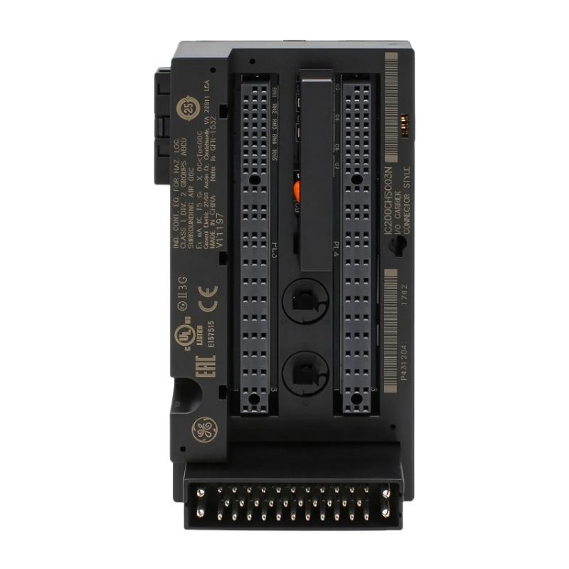
| VersaMax carrier base | Provides mechanical and electrical mounting | Select a compatible IC200CHS carrier |
| VersaMax power supply | Supplies system power | Check power capacity and system requirements |
| 24 V DC field power supply | Powers external analog output circuits | Maintain the required 18–30 V DC range |
| Analog control valve | Receives current commands for position control | Verify 4–20 mA or 0–20 mA compatibility |
| Variable frequency drive | Receives analog speed references | Check analog input type and scaling |
| Pressure regulator | Adjusts pressure according to a control command | Verify signal range and electrical loading |
| HMI | Provides operator setpoints and monitoring | Typically communicates through the PLC |
| Analog signal wiring | Carries current output signals | Follow terminal, grounding, and shielding requirements |
Compatibility should be confirmed against the exact VersaMax hardware revision and system documentation. The carrier, power supply, controller, and field devices are not necessarily included with the analog output module.
Alternative Models and Replacement Considerations
When replacing an IC200ALG326F, the most important factors are the number of channels, output signal type, resolution, electrical requirements, and module revision.
| Related Model | Product Description | Main Difference |
|---|---|---|
| IC200ALG325 | VersaMax 13-bit analog voltage output module | Provides voltage outputs rather than current outputs |
| IC200ALG327 | VersaMax 13-bit analog voltage output module | Provides 12 voltage output channels |
| IC200ALG328 | VersaMax 13-bit analog current output module | Provides 12 current output channels |
| IC200ALG331 | VersaMax isolated voltage/current analog module | Different channel count and isolation characteristics |
| IC200ALG320 | VersaMax 12-bit current output module | Different resolution and channel configuration |
| IC200ALG321 | VersaMax 12-bit voltage output module | Voltage output rather than current output |
These models are related VersaMax analog output products, not automatically interchangeable replacements.
Before selecting an alternative, verify:
- Number of required output channels.
- Current or voltage signal type.
- 4–20 mA or 0–20 mA operating range.
- Resolution and accuracy requirements.
- External field power requirements.
- Carrier and backplane compatibility.
- Terminal arrangement and wiring.
- Output default behavior.
- PLC configuration and program compatibility.
A replacement should be evaluated at the system level. Even when two modules provide similar output functions, differences in channel count, resolution, configuration, or terminal assignment can affect commissioning and operation.
Key Advantages
Eight Analog Current Outputs
The eight-channel design allows one module to control several compatible field devices, helping reduce the number of separate analog output modules required.
13-Bit Output Resolution
The 13-bit conversion capability provides graduated output commands for process-control applications requiring more than simple discrete signals.
Configurable Current Ranges
The module supports 4–20 mA and 0–20 mA operation through jumper configuration, allowing it to be used with different types of industrial instruments and actuators.
VersaMax Distributed I/O Integration
The module is designed for the VersaMax platform and can be installed as part of a distributed PLC I/O architecture.
Field Power Monitoring
The FLD PWR indicator provides a convenient visual indication of field-side power status, while the OK indicator indicates backplane power availability.
Configurable Output Behavior
The output state can be configured to hold the last value or return to the low-end range under specified communication or backplane interruption conditions.
Compact Installation
The module’s supplied dimensions of 110 × 66.8 × 50 mm support compact installation in compatible VersaMax I/O assemblies.
Technical FAQs
1. What is the GE IC200ALG326F?
The IC200ALG326F is a GE Fanuc VersaMax analog current output module. It provides eight single-ended output channels for converting PLC digital data into analog current signals.
2. How many output channels does the module provide?
It provides eight analog current output channels arranged in one group.
3. What is the output signal range?
The default output range is 4–20 mA. The module can also be configured for 0–20 mA using the specified jumper arrangement.
4. What is the resolution of the IC200ALG326F?
The module is specified as a 13-bit analog current output module.
5. Does the module require an external power supply?
Yes. The analog output circuits require an external DC field supply in the documented range of 18–30 V DC.
6. What do the FLD PWR and OK indicators mean?
The FLD PWR LED indicates the presence of user-side field power. The OK LED indicates that backplane power is present.
7. Can the module control a 4–20 mA valve positioner?
Yes, provided the valve positioner accepts a compatible current input and the module is configured correctly. The PLC scaling, module jumper settings, and field-device signal range must match.
8. What happens if PLC communication is interrupted?
The output behavior can be configured to hold the last state or move to the configured low-end value. The selected behavior depends on the jumper settings and requires the external field power supply to remain available.
9. Is the module individually isolated channel by channel?
No. The eight channels are arranged in one group and do not provide channel-to-channel isolation. Review grounding and field-device wiring requirements before connecting multiple devices.
10. Can the IC200ALG326F be replaced by an IC200ALG328?
Not automatically. The IC200ALG328 is a related 12-channel current output module, while the IC200ALG326F provides eight channels. Check system configuration, wiring, scaling, and hardware compatibility before replacement.
Procurement and Maintenance Recommendations
When purchasing the GE IC200ALG326F, verify the complete model number and revision suffix. The final letter is important because it identifies a particular hardware revision. Do not assume that a module with a similar base number has identical hardware or documentation.
For new, surplus, or refurbished units, inspect the module label, terminal condition, housing, connector contacts, and visible signs of overheating or physical damage. Request clear product photographs and confirm the supplier’s testing and warranty arrangements.
During maintenance, check the external field power supply, module indicators, carrier connection, output wiring, and terminal condition. If an output channel does not produce the expected current, verify the PLC output value, module configuration, jumper settings, field supply, wiring, and connected device before concluding that the module is defective.
For critical applications, periodically test the output channels using suitable current-measuring equipment. Record the expected current range and corresponding process value for each channel.
Keeping a backup of the PLC program, output scaling, channel assignments, and jumper configuration can reduce troubleshooting time and support faster replacement.
Conclusion
The GE IC200ALG326F VersaMax Analog Output Module is an eight-channel, 13-bit current output module designed for industrial PLC and distributed I/O systems. It supports 4–20 mA and 0–20 mA output ranges and requires an external 18–30 V DC field power supply.
With its eight single-ended output channels, the module can provide analog control signals for compatible valves, drives, regulators, and other industrial field devices. Correct carrier selection, field power, jumper configuration, signal wiring, and PLC scaling are essential for reliable operation.
For maintenance and replacement projects, confirming the exact IC200ALG326F revision and system compatibility helps ensure that the module can perform its intended role in the VersaMax automation system.