

ProductPRODUCT
Featured products
Contact Us
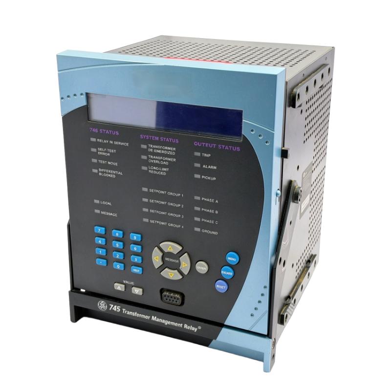
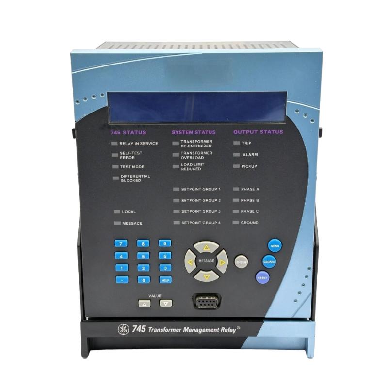
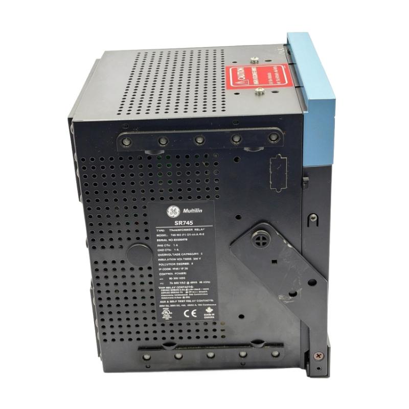
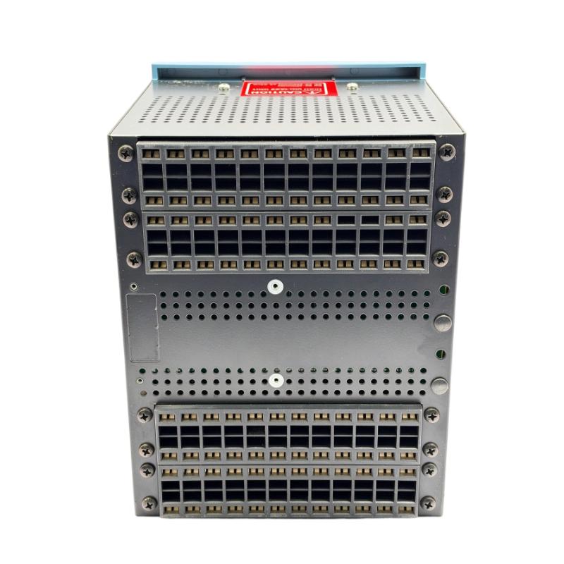
- GE
- 745-W2-P1-G1-HI-E
- Multilin 745 Transformer Management Relay
- USA
- 252 x 216 x 224 mm
- 8.4 kg
- Xiamen, China
- New & In Stock
- T/T, PayPal, Western Union
- 1 Year
- 1-3 Working Days
- DHL, UPS, TNT, FedEx and EMS.
- 24-Hour Service
- COO
- 5
Our advantage

Global Logistics
We have a 10-year logistics and express cooperation agreement, so our products can be shipped to any place in the world.

Brand new and original
Our products are imported in bulk from the place of origin. Because of the cooperative relationship, our products are all original and 100% new.

24-hour service
We provide 7*24 hours service to our customers. We will be there whenever you need us.

Price advantage
All our products are priced very favorably because we have our own warehouse and supply.
| Company Information | |||
| [email protected] | |||
| Mobile | +8615980777398 | ||
| +8615980777398 | |||
| 15980777398 |
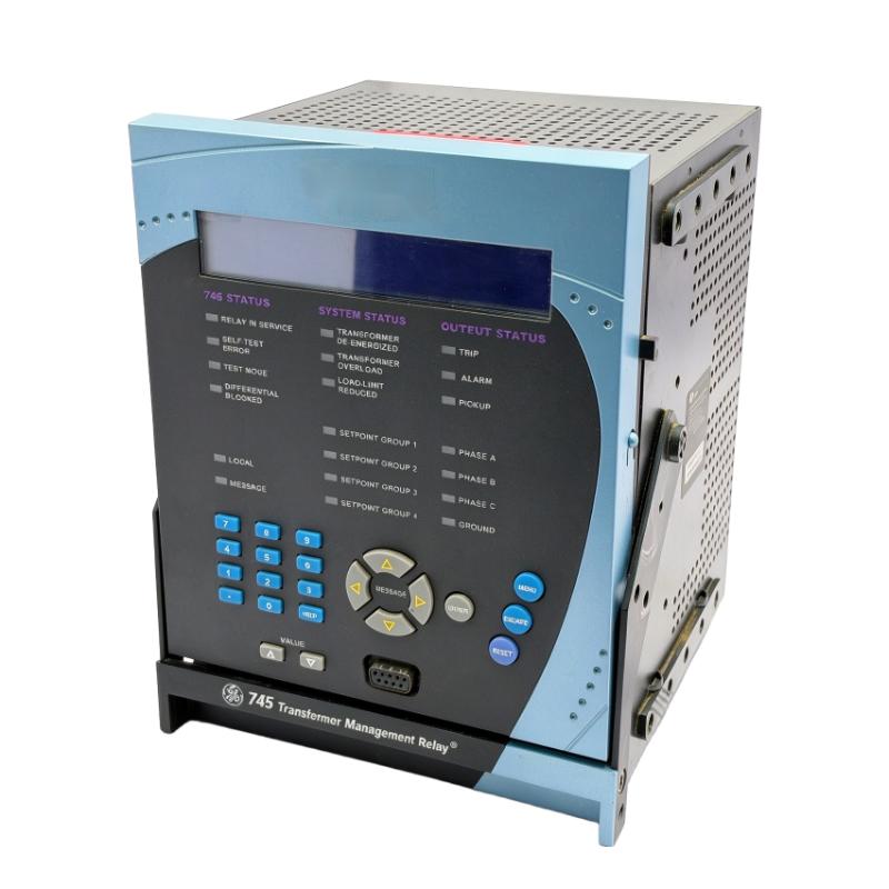
Product Overview
The GE Multilin 745-W2-P1-G1-HI Transformer Management Relay is a microprocessor-based protection and monitoring device designed for industrial power systems and utility transformer installations. It belongs to the GE Multilin 745 Transformer Management Relay family and is intended to provide protection, monitoring, and diagnostic functions for power transformers.
Transformers are essential components in electrical distribution networks, substations, power generation facilities, and industrial plants. Electrical faults, overloads, abnormal operating conditions, and insulation deterioration can affect transformer reliability and service life. A dedicated transformer protection relay monitors electrical measurements and evaluates operating conditions so that appropriate alarms or protective actions can be initiated.
The 745-W2-P1-G1-HI is configured for two windings per phase. Its P1 designation identifies 1 A phase current inputs, while G1 identifies 1 A ground current inputs. The HI suffix specifies a high-range auxiliary control power supply supporting 90–300 V DC or 70–265 V AC at 48–62 Hz.
The GE Multilin 745 platform combines transformer differential protection with additional protection, measurement, event recording, and diagnostic capabilities. Depending on the complete relay configuration and enabled functions, it can help operators identify abnormal electrical conditions and investigate transformer disturbances.
This model is suitable for applications where the protection system must monitor a two-winding transformer and coordinate with the surrounding electrical protection and control equipment. Correct current-transformer selection, relay settings, trip-circuit wiring, and commissioning are essential for reliable operation.
Technical Specifications
| Parameter | Specification |
|---|---|
| Brand | GE Multilin |
| Manufacturer | General Electric |
| Model | 745-W2-P1-G1-HI |
| Product Series | Multilin 745 |
| Product Type | Transformer Management Relay |
| Application | Two-winding transformer protection |
| Transformer Configuration | W2 – Two windings per phase |
| Phase Current Input | P1 – 1 A |
| Ground Current Input | G1 – 1 A |
| Control Power | HI – High-range AC/DC supply |
| DC Control Power Range | 90–300 V DC |
| AC Control Power Range | 70–265 V AC |
| AC Frequency | 48–62 Hz |
| Protection Functions | Transformer differential and overcurrent protection, subject to configuration |
| Monitoring Functions | Electrical measurements, transformer operating data, and diagnostics |
| Event Recording | Supported by the 745 platform |
| Communication | Serial communication capabilities; interface and protocol depend on configuration |
| Dimensions Provided | 252 × 216 × 224 mm |
| Weight Provided | 8.4 kg |
| Typical Installation | Electrical protection panel or substation control cabinet |
| Product Family Status | Legacy product family |
Note: The dimensions and weight above are the supplied listing values. Confirm the physical unit, mounting arrangement, and exact configuration before panel design or shipping.
Function and Working Principle
The GE Multilin 745 relay continuously evaluates electrical signals received from instrument transformers and other configured measurement inputs. It compares measured operating conditions with programmed protection settings and determines whether an alarm or protective operation is required.
1. Transformer Differential Protection
Transformer differential protection is one of the principal functions of the Multilin 745 platform.
The relay compares current measurements from the transformer windings. Under normal operating conditions, the currents should have a predictable relationship after accounting for transformer ratio and phase displacement.
When an internal transformer fault occurs, the difference between the measured currents may increase beyond the configured operating threshold. The differential protection element can then initiate a trip command to isolate the affected transformer.
Correct current-transformer ratios, polarity, wiring, and relay configuration are essential. Incorrect settings can cause unwanted operation or reduce the sensitivity of the protection system.
2. Overcurrent Protection
Overcurrent protection monitors current levels and evaluates whether they exceed configured pickup values.
Depending on the enabled elements and settings, the relay can provide protection against excessive current conditions associated with external faults, abnormal loading, or other disturbances.
Time-current characteristics and coordination settings should be selected according to the transformer rating, upstream and downstream protection devices, and the overall power-system protection study.
3. Ground-Fault Monitoring
Ground-current measurements help identify current conditions associated with earth faults. The G1 configuration specifies 1 A ground-current inputs.
The relay can use these measurements as part of its ground-related protection strategy. The availability of specific restricted ground-fault functions depends on the selected options and configuration. The R option is a separately identified ordering option and should not be assumed to be included in the base catalog number.
4. Harmonic Restraint and Transformer Inrush Considerations
Transformer energization can produce magnetizing inrush current. This current may be substantially different from normal load current and can resemble an internal fault under some measurement conditions.
Transformer differential protection therefore needs appropriate restraint or blocking logic to distinguish inrush conditions from genuine internal faults.
The Multilin 745 platform provides harmonic-related protection features intended to support reliable transformer differential protection. Correct configuration is important to maintain both security and sensitivity.
5. Monitoring and Diagnostics
The relay provides measurement and diagnostic capabilities that help operators evaluate transformer operating conditions and investigate protection events.
Depending on the installed configuration, available information may include current measurements, operating records, event information, and fault-related data.
These functions can support maintenance planning and troubleshooting by helping engineers understand the conditions that preceded a protection operation.
6. Auxiliary Control Power
The HI suffix identifies the high-range control power supply configuration.
The supported ranges are:
- 90–300 V DC
- 70–265 V AC
- 48–62 Hz for AC operation
The control supply must remain within the specified range. Before energizing the relay, verify the actual auxiliary supply, terminal connections, and equipment nameplate.
Role in Industrial Power Systems
The 745-W2-P1-G1-HI operates as a dedicated electrical protection device rather than a general-purpose PLC module. It monitors transformer electrical conditions and works with circuit breakers, current transformers, control circuits, and station monitoring systems.
Transformer Protection
The relay can serve as a primary or backup protection device in a suitable transformer protection scheme. Its protection functions help detect abnormal operating conditions and provide trip or alarm outputs according to the configured logic.
The exact protection arrangement depends on transformer design, system grounding, CT connections, and the project’s protection philosophy.
Substation Automation
In substations, transformer protection relays form part of the wider protection and control architecture. They may exchange status, measurement, and event information with station control or supervisory systems through supported communication interfaces.
The communication protocol and available ports should be verified against the specific hardware and configuration. Do not assume that every optional communication feature is installed on this base model.
Circuit Breaker Coordination
When a protection element identifies a condition requiring isolation, the relay can operate configured output contacts connected to the relevant trip circuit.
Coordination with circuit breakers and other protective devices is essential. Engineers must verify trip-circuit voltage, contact ratings, wiring, interlocks, and protection coordination before commissioning.
Electrical Monitoring and Maintenance
The relay’s monitoring and recording functions can help maintenance personnel investigate abnormal events and evaluate transformer operating conditions.
Recorded information can be useful when reviewing fault events, identifying recurring disturbances, and determining whether further transformer inspection is necessary.
Industrial Applications
The GE Multilin 745-W2-P1-G1-HI is intended for transformer protection in electrical power systems. Typical applications include:
1. Industrial Power Distribution
Manufacturing plants often use transformers to supply different voltage levels to production equipment, motor-control centers, and auxiliary systems.
A transformer protection relay can monitor electrical conditions and provide protective functions for transformers supplying critical plant loads.
2. Utility Substations
Utility substations use power transformers to transfer electrical energy between transmission and distribution voltage levels.
The Multilin 745 platform can be incorporated into suitable two-winding transformer protection schemes, subject to the project’s current-transformer arrangement and protection requirements.
3. Power Generation Facilities
Power stations contain transformers used for generator step-up, station service, and auxiliary distribution.
A dedicated transformer relay can provide protection and monitoring for appropriately configured transformer applications.
4. Oil and Gas Facilities
Oil and gas installations depend on electrical distribution systems for pumps, compressors, processing equipment, and utility services.
Transformer protection is important for maintaining electrical reliability and limiting the consequences of transformer faults.
5. Mining and Heavy Industry
Mining operations and heavy industrial facilities often use transformers to supply large electrical loads across distributed installations.
A transformer management relay can support protection and monitoring within the electrical distribution network.
6. Infrastructure and Commercial Power Systems
Large infrastructure facilities may use transformers to supply buildings, transport systems, water facilities, and other essential services.
The relay can be considered for compatible two-winding transformer protection applications where its ratings and functions meet the system design.
Installation and System Integration
Correct installation and commissioning are essential for transformer protection relays. Incorrect CT wiring, control power, or protection settings can compromise the protection scheme.
1. Verify the Auxiliary Power Supply
The HI configuration supports 90–300 V DC or 70–265 V AC at 48–62 Hz.
Before applying power, confirm that the available supply falls within the specified range. Verify terminal assignments and polarity for DC connections according to the manufacturer’s documentation.
2. Confirm Current Transformer Compatibility
The P1 and G1 designations identify 1 A phase and ground current input configurations.
The current-transformer secondary ratings must match the relay’s input requirements. Confirm CT ratios, polarity, burden, wiring, and grounding arrangements before connecting the relay.
Never assume that a 5 A CT secondary can be connected directly to a 1 A input configuration.
3. Install in a Suitable Protection Panel
The supplied dimensions are 252 × 216 × 224 mm. Confirm the manufacturer’s mounting drawing and actual enclosure requirements before preparing the panel.
Allow sufficient clearance for wiring, ventilation, inspection, and maintenance. Protect the relay from excessive vibration, conductive dust, moisture, and environmental conditions outside its specified operating limits.
4. Configure Transformer Data
Relay settings should reflect the actual transformer and power-system design.
Important configuration information may include:
- Transformer rated power.
- Primary and secondary voltage ratings.
- Transformer vector group.
- Current-transformer ratios.
- Phase and ground current input ratings.
- System frequency.
- Differential protection settings.
- Overcurrent pickup and timing values.
- Alarm and trip output assignments.
Incorrect transformer or CT data can cause unreliable protection operation.
5. Configure Trip and Alarm Circuits
Connect the relay outputs to the appropriate circuit-breaker trip circuits, alarm systems, and control equipment.
Verify output contact ratings and the external control-circuit voltage. Perform trip-circuit continuity checks and functional testing before placing the protection scheme into service.
6. Test and Commission the Relay
Commissioning should include inspection, configuration verification, secondary injection testing, trip logic testing, and communication checks where applicable.
Protection engineers should confirm that each enabled element operates according to the approved protection study. Test results and final settings should be documented for future maintenance.
Compatible System Components
The 745-W2-P1-G1-HI is normally used as part of a complete transformer protection and control system.
| Component | Function | Integration Considerations |
|---|---|---|
| Power transformer | Equipment being protected | Confirm winding configuration, voltage, power rating, and vector group |
| Phase current transformers | Supply phase-current measurements | Must match the 1 A P1 input configuration |
| Ground current transformers | Supply ground-current measurements | Must match the 1 A G1 input configuration |
| Circuit breaker | Disconnects the transformer when required | Verify trip-coil ratings and protection coordination |
| DC or AC control supply | Powers the relay | Must remain within the HI supply range |
| Protection panel | Houses the relay and associated wiring | Confirm mounting dimensions and environmental conditions |
| Station control system | Supervises electrical equipment | Confirm supported communication interfaces and protocols |
| Alarm annunciator | Displays protection and equipment alarms | Verify output contact assignments and alarm logic |
| Engineering workstation | Supports configuration and maintenance | Use compatible manufacturer software and approved procedures |
The components listed are typical parts of a transformer protection installation. They are not necessarily supplied with the relay.
Alternative Models and Replacement Considerations
The GE Multilin 745 is a legacy transformer protection platform. When replacing an existing unit, the complete catalog number and installed options must be compared.
| Alternative | Replacement Considerations |
|---|---|
| GE Multilin 745-W2 variants | May provide a closer replacement path, but CT ratings, control power, and options must match |
| GE Multilin 745-W3 variants | Designed for three-winding transformer configurations; not a direct substitute for a two-winding application without engineering review |
| GE Multilin 745 models with P5 inputs | Use different 5 A phase-current input ratings and cannot be treated as direct replacements for a 1 A input model |
| GE Multilin T60 Transformer Protection System | A different protection platform that may be considered for an upgrade after application review |
| Other modern transformer differential relays | May support replacement or modernization, but require protection-study review and engineering changes |
Before selecting a replacement, compare:
- Number of transformer windings.
- Phase CT input ratings.
- Ground CT input ratings.
- Auxiliary control power range.
- Differential protection characteristics.
- Overcurrent protection functions.
- Ground-fault protection options.
- Communication interfaces and protocols.
- Display and operator-interface configuration.
- Analog input and output requirements.
- Mounting dimensions and terminal arrangements.
A relay with the same family name is not necessarily electrically or functionally interchangeable. Replacement should be approved by qualified protection engineers.
Key Advantages
Dedicated Transformer Protection
The Multilin 745 platform is designed specifically for transformer protection and management rather than general-purpose automation control.
Two-Winding Transformer Configuration
The W2 designation identifies a configuration intended for two windings per phase, supporting suitable transformer protection schemes.
1 A Current Input Configuration
The P1 and G1 options identify 1 A phase and ground current input ratings, allowing integration with compatible instrument transformers.
Wide Auxiliary Power Range
The HI control power configuration supports a broad AC/DC supply range, helping accommodate different substation and industrial control power arrangements.
Differential Protection Capability
Transformer differential protection helps identify internal faults by comparing current measurements from the transformer windings.
Monitoring and Event Information
Measurement, recording, and diagnostic functions can help engineers investigate disturbances and support maintenance activities.
Integration into Protection Systems
The relay can work with current transformers, circuit breakers, alarm circuits, and station control systems as part of a coordinated electrical protection architecture.
Technical FAQs
1. What is the GE 745-W2-P1-G1-HI used for?
It is a transformer management and protection relay designed for two-winding transformer applications. It provides protection, monitoring, and diagnostic functions within industrial and utility power systems.
2. What does W2 mean in the model number?
W2 identifies a configuration for two windings per phase.
3. What does P1 mean?
P1 identifies the 1 A phase current input configuration. The connected phase current transformers must have compatible secondary ratings.
4. What does G1 mean?
G1 identifies the 1 A ground current input configuration. The ground-current measurement circuit must be designed for the corresponding input rating.
5. What does HI mean?
HI identifies the high-range auxiliary control power supply. It supports 90–300 V DC or 70–265 V AC at 48–62 Hz.
6. Does the relay support transformer differential protection?
Yes. Transformer differential protection is one of the principal functions of the GE Multilin 745 platform. Correct CT configuration and relay settings are essential.
7. Does this exact model include restricted ground-fault protection?
The R suffix identifies the restricted ground-fault option in the 745 ordering system. Since the supplied model number ends at HI and does not include the R suffix, that option should not be assumed to be installed.
8. Can this relay be connected to a PLC?
It can be integrated into a broader monitoring and control system through supported interfaces and configured signals. However, it is a dedicated protection relay, not a PLC I/O module. Confirm the actual communication ports, protocols, and available signals before planning integration.
9. What should be checked before purchasing a used relay?
Verify the complete catalog number, nameplate, current input ratings, control power range, hardware condition, firmware information, and available test records. Confirm whether the relay has the required optional functions for the intended application.
10. Can a 5 A CT be connected to this model?
The P1 and G1 configuration identifies 1 A inputs. A 5 A CT secondary should not be connected directly unless an approved and properly engineered interface arrangement is provided. Confirm compatibility with the manufacturer documentation and protection design.
Procurement and Maintenance Recommendations
The GE Multilin 745-W2-P1-G1-HI is a specialized electrical protection device. Procurement should therefore focus on configuration accuracy rather than appearance or general product-family similarity.
Before ordering, verify the complete catalog number and confirm that the two-winding configuration, 1 A phase inputs, 1 A ground inputs, and HI auxiliary power supply match the existing protection scheme.
For used or surplus units, request clear photographs of the nameplate, front panel, rear terminals, and connectors. Ask for available functional test records and confirm the hardware and firmware information where possible.
During maintenance, inspect terminal connections, wiring condition, panel ventilation, auxiliary power quality, and the integrity of the CT circuits. Periodic testing should follow the plant’s protection maintenance schedule and applicable electrical safety procedures.
Keep a documented backup of relay settings and event information where supported. Before replacing or reconfiguring the relay, ensure that the approved protection settings and coordination study are available.
Because the 745 is a legacy protection platform, replacement planning should include a review of the complete transformer protection scheme. A modern replacement may require new wiring, updated communication arrangements, revised settings, and renewed commissioning tests.
Conclusion
The GE Multilin 745-W2-P1-G1-HI Transformer Management Relay is a dedicated protection and monitoring device for two-winding transformer applications. Its configuration includes 1 A phase current inputs, 1 A ground current inputs, and a high-range auxiliary supply supporting 90–300 V DC or 70–265 V AC.
The 745 platform provides transformer differential protection, overcurrent protection, monitoring, and diagnostic capabilities to support reliable operation of industrial and utility power systems. Accurate CT matching, correct auxiliary power, and carefully engineered protection settings are essential for safe and dependable operation.
For maintenance and replacement projects, confirming the complete model number and installed options is the most important step in ensuring compatibility with the existing transformer protection system.