

ProductPRODUCT
Featured products

Contact Us
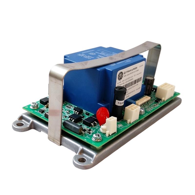


- GE
- 151X1225EK01PC04
- Battery Charger Assembly
- USA
- 216 × 52 × 152 mm
- 0.55 kg
- Xiamen, China
- New & In Stock
- T/T, PayPal, Western Union
- 1 Year
- 1-3 Working Days
- DHL, UPS, TNT, FedEx and EMS.
- 24-Hour Service
- COO
- 5
Our advantage

Global Logistics
We have a 10-year logistics and express cooperation agreement, so our products can be shipped to any place in the world.

Brand new and original
Our products are imported in bulk from the place of origin. Because of the cooperative relationship, our products are all original and 100% new.

24-hour service
We provide 7*24 hours service to our customers. We will be there whenever you need us.

Price advantage
All our products are priced very favorably because we have our own warehouse and supply.
| Company Information | |||
| [email protected] | |||
| Mobile | +8615980777398 | ||
| +8615980777398 | |||
| 15980777398 |
Product Overview
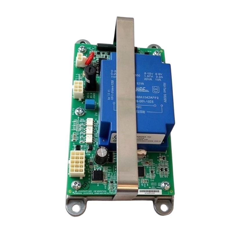
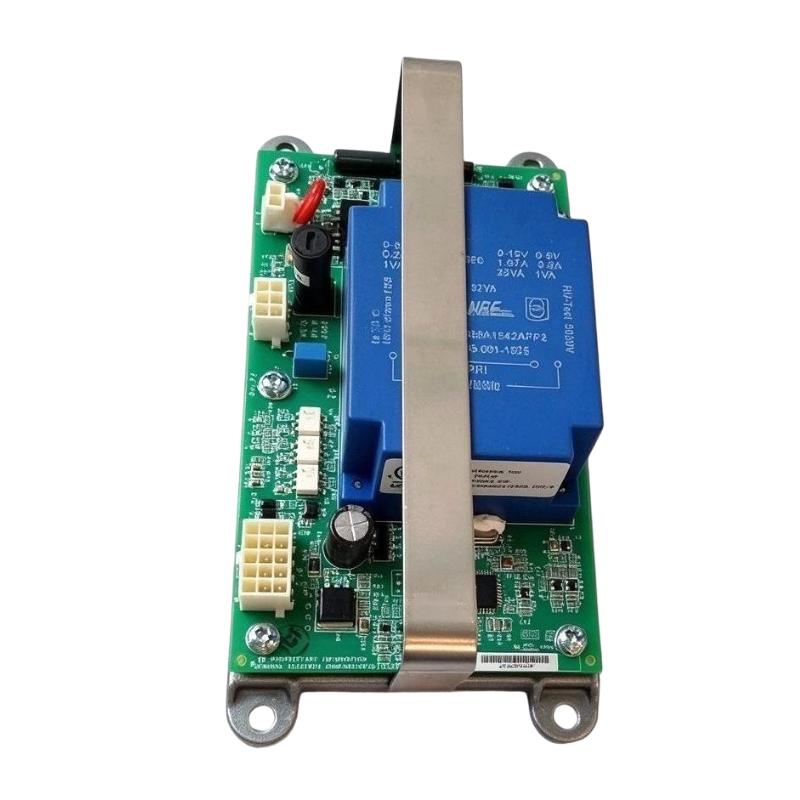
The GE 151X1225EK01PC04 Battery Charger Assembly is an industrial power and battery-charging component developed for GE energy and electrical control equipment. It belongs to the GE 151X board and module product family and is identified as a battery charger assembly used in industrial power-related applications.
Industrial control and energy systems require dependable auxiliary power to support control electronics, monitoring devices, and backup power arrangements. Battery charging assemblies help maintain the required battery condition so that designated equipment can continue to receive power when normal supply conditions are interrupted or when backup operation is required.
The 151X1225EK01PC04 is associated with a 12 V DC, 2 A output configuration. Available product information also identifies a 230 V AC input, with a nominal input frequency of 50–60 Hz. These electrical characteristics make accurate supply verification essential before installation or replacement.
This assembly is identified by its complete part number, which should be used when sourcing replacement equipment. Similar-looking GE charger boards may have different connector arrangements, revisions, output characteristics, or intended applications. The full catalog number and board revision should therefore be checked before ordering.
The 151X1225EK01PC04 is relevant to maintenance work involving GE industrial power and energy equipment. Its condition and compatibility should be evaluated as part of the complete charging and backup-power system rather than as an isolated electronic board.
Technical Specifications
| Parameter | Specification |
|---|---|
| Brand | GE |
| Manufacturer | General Electric |
| Model | 151X1225EK01PC04 |
| Product Series | 151X Boards and Modules |
| Product Type | Battery Charger Assembly |
| Associated Part Number | 109W6930P001 |
| Input Voltage | 230 V AC |
| Input Frequency | 50–60 Hz |
| Input Current | 0.5 A (listed specification) |
| Output Voltage | 12 V DC |
| Output Current | 2 A |
| Output Power | 24 W at 12 V DC / 2 A |
| Mounting Strategy | Metal backplane mounting |
| Mounting Features | Six screw standoffs |
| Installation Holes | Four factory-drilled holes |
| Connectors | Three plugs, identified as PL1–PL3 |
| Board Revision | BA (reported in available product data) |
| Dimensions Provided | 216 × 52 × 152 mm |
| Weight Provided | 0.55 kg |
| Typical Function | Industrial battery charging and auxiliary DC power |
Note: Specifications are based on available product information and the supplied listing data. Confirm the input, output, connector configuration, revision, and physical measurements against the actual unit before installation.
Function and Working Principle
The GE 151X1225EK01PC04 combines battery-charging and power-conversion functions within an industrial assembly. Its purpose is to provide a designated DC output for compatible equipment and support the charging requirements of the associated battery arrangement.
1. AC Input and Power Conversion
The assembly is associated with a 230 V AC input supply. Its power-conversion circuitry processes the incoming electrical energy to provide a suitable DC output.
The documented output specification is 12 V DC at up to 2 A. This output can support the designated charging circuit or compatible DC load, provided that the connected equipment’s voltage, current, and operating requirements match the assembly’s specifications.
Input voltage and frequency must be checked before energizing the equipment. Applying an incorrect supply can damage the charger or connected control components.
2. Battery Charging Function
Industrial backup batteries require controlled charging to maintain their operating condition. A charger assembly supplies the electrical energy needed by the associated battery system according to its designed charging characteristics.
The 151X1225EK01PC04 is identified as a battery charger assembly. However, the exact battery chemistry, charging stages, charge termination thresholds, and temperature compensation characteristics should be confirmed from the correct technical documentation for the installed system.
A replacement charger should not be selected based solely on its nominal output voltage. Its charging characteristics must also be suitable for the connected battery.
3. DC Output Supply
The listed 12 V DC / 2 A output provides a defined electrical supply for compatible charging or auxiliary power circuits.
Stable DC power is important in industrial systems because voltage abnormalities may affect electronic control devices, monitoring circuits, and other connected equipment.
The output should be checked under suitable test conditions before the assembly is returned to service. Verify polarity, voltage regulation, connector condition, and the behavior of the connected battery circuit.
4. Electrical Connection and Distribution
The assembly uses three plugs identified as PL1, PL2, and PL3 in available product information. These connectors form part of its electrical interface with the surrounding equipment.
Connector identification is particularly important during replacement. The correct plug positions, pin assignments, wiring orientation, and board revision must be confirmed rather than assumed from the physical appearance of another charger assembly.
Role in Industrial Control and Energy Systems
Battery charger assemblies support the auxiliary power arrangements used in industrial electrical and energy equipment. Their function is closely related to system availability, backup power readiness, and the condition of connected batteries.
Battery Backup Support
A backup battery arrangement can provide power to designated equipment when the normal supply is unavailable. The charger helps maintain battery readiness during normal operation.
The charger is only one part of this arrangement. Battery condition, protection devices, wiring, monitoring circuits, and the connected load all influence the performance of the complete backup-power system.
Auxiliary DC Power
Industrial equipment often contains electronic circuits that require a stable DC supply. A compatible charger assembly may support the designated auxiliary power circuit while maintaining the associated battery-charging function.
The exact load supported by this model should be confirmed against the equipment wiring diagram and original system documentation.
Equipment Availability
A properly maintained charging system helps reduce the risk of backup batteries being unavailable when needed. Regular inspection of the charger, battery connections, and DC output can help identify developing problems before they affect system operation.
Integration with GE Energy Equipment
The 151X1225EK01PC04 belongs to the GE 151X product family and is associated with GE energy-related equipment. Its installation should follow the original equipment configuration, including mounting arrangements, connectors, and electrical ratings.
The 151X series designation alone does not establish compatibility with every GE control or energy system. Confirm the complete part number and revision before replacement.
Industrial Applications
The 151X1225EK01PC04 is intended for applications where its specified charging and DC power characteristics match the equipment requirements.
1. Industrial Energy Equipment
Industrial energy systems may use dedicated charger assemblies to maintain batteries associated with auxiliary power circuits. The charger helps support the electrical infrastructure required by designated monitoring and control equipment.
2. Backup Battery Systems
Backup batteries are used in applications where selected electrical loads need continued power during supply interruptions. A compatible charger helps maintain battery charge during normal operation.
The battery type and charging profile must match the charger’s design.
3. GE Electrical and Power Assemblies
The 151X1225EK01PC04 may be encountered in maintenance and repair projects involving GE 151X boards and related power equipment.
When replacing the assembly, technicians should check the original equipment documentation, connector locations, mounting points, and revision information.
4. Industrial Control Power Circuits
Some industrial control installations use dedicated DC power circuits for auxiliary electronics and designated control functions. A suitable charger assembly can support these circuits as part of a broader power architecture.
The actual load and charging connections should be identified from the system wiring diagram.
5. Equipment Maintenance and Refurbishment
The component may be required during the repair or refurbishment of existing GE equipment. Accurate part-number identification is important when maintaining older installations or sourcing replacement assemblies.
Installation and System Integration
Correct installation is essential for electrical safety and reliable battery-charging operation.
1. Verify the Input Supply
The listed input specification is 230 V AC at 50–60 Hz. Before installation, confirm that the available supply matches the actual unit’s nameplate and the original system design.
Check the input wiring, protective devices, grounding arrangement, and isolation requirements before connecting the assembly.
2. Inspect the Mounting Arrangement
The assembly is associated with a metal backplane mounting design. Available product information identifies six screw standoffs and four factory-drilled installation holes.
The supplied dimensions are 216 × 52 × 152 mm. Verify these measurements against the actual unit before preparing the mounting location.
Ensure that the assembly is securely fixed and that sufficient space is available for wiring access and heat dissipation.
3. Check Connector Identification
The available product description identifies three plugs: PL1, PL2, and PL3.
Before disconnecting an existing assembly, record the connector positions and wiring arrangement. Confirm pin assignments and polarity using the appropriate wiring diagram.
Do not rely only on connector shape or cable color when installing a replacement.
4. Verify Battery Compatibility
Confirm the battery voltage, chemistry, capacity, and charging requirements before connecting the charger. The listed 12 V DC output does not by itself establish compatibility with every 12 V battery.
The charging profile must be appropriate for the connected battery. Incorrect charging parameters can reduce battery service life or create unsafe operating conditions.
5. Inspect the DC Output
After installation, verify the output voltage and polarity using appropriate test equipment. Check that the charger operates within its specified output range and that the connected circuit does not exceed its rated current.
Investigate abnormal voltage, excessive heating, unusual noise, or unstable operation before returning the system to service.
6. Perform Functional Testing
A suitable commissioning procedure should include:
- Input voltage verification.
- Connector and wiring inspection.
- Output voltage and polarity checks.
- Battery connection verification.
- Charging operation checks.
- Inspection for abnormal temperature or noise.
- Confirmation of associated system alarms and indications.
Record the results for future maintenance reference.
Compatible System Components
The 151X1225EK01PC04 operates as part of a larger electrical and battery-charging arrangement.
| Component | Function | Compatibility Considerations |
|---|---|---|
| Compatible backup battery | Stores electrical energy for backup operation | Confirm battery voltage, chemistry, capacity, and charging profile |
| AC input supply | Provides energy to the charger assembly | Verify the 230 V AC input and frequency requirements |
| DC power circuit | Receives the charger output | Confirm the 12 V DC output requirements and current limits |
| GE control or energy equipment | Provides the operating environment | Verify the exact equipment model and approved configuration |
| Connector harness | Connects the assembly to surrounding circuits | Check PL1–PL3 positions, pin assignments, and wiring |
| Metal mounting backplane | Supports the charger assembly | Confirm mounting-hole locations and mechanical clearance |
| Circuit protection | Protects the input and connected electrical circuits | Follow the original system design and applicable electrical codes |
| Battery monitoring circuit | Monitors battery condition where provided | Confirm signal interfaces and system-specific requirements |
The listed components describe a typical system arrangement. They should not be interpreted as items included with the 151X1225EK01PC04.
Alternative Models and Replacement Considerations
When replacing a GE battery charger assembly, a similar product name or output voltage is not sufficient to establish compatibility.
| Alternative or Related Part | Consideration |
|---|---|
| GE 151X1225EK01PC03 | A related charger-board part number, but revision and electrical compatibility must be verified |
| GE 109W6930P001 | Associated part number reported for the 151X1225EK01PC04; confirm the exact assembly and revision |
| GE 151X charger assemblies | Other assemblies in the same family may have different functions and connector configurations |
| GE-compatible industrial DC charger | May be considered only after verifying input, output, charging profile, and system interfaces |
Before selecting a replacement, compare:
- Complete part number and board revision.
- AC input voltage and frequency.
- DC output voltage and current.
- Battery chemistry and charging profile.
- Connector count and pin assignments.
- Mounting dimensions and backplane arrangement.
- Protection and monitoring functions.
- Original equipment compatibility.
A replacement with a nominal 12 V output is not automatically suitable. The charging characteristics and electrical interfaces must also match the original design.
Key Advantages
Integrated Charging and DC Power Function
The assembly combines battery-charging and DC power functions within a dedicated industrial component, supporting the designated power architecture.
Defined Output Rating
Its listed 12 V DC / 2 A output provides a clear reference for checking electrical compatibility with the intended system.
Industrial Mounting Design
The metal backplane and standoff arrangement provide a defined mounting method for installation within compatible equipment.
Identifiable Connector Arrangement
The three-plug configuration provides identifiable connection points for system integration, subject to verification of the correct wiring and pin assignments.
Maintenance and Replacement Support
The complete part number helps technicians identify the required assembly when repairing or maintaining existing GE equipment.
Application-Specific Integration
The charger assembly is intended for use within a designated industrial power arrangement rather than as a general-purpose consumer battery charger.
Technical FAQs
1. What is the GE 151X1225EK01PC04?
It is a GE Battery Charger Assembly belonging to the 151X Boards and Modules family. It is associated with industrial battery-charging and DC power applications.
2. What is the input voltage?
Available product information lists a 230 V AC input at 50–60 Hz. Confirm the actual unit’s nameplate before connecting the supply.
3. What is the DC output rating?
The listed output is 12 V DC at 2 A. Confirm that this rating matches the requirements of the connected battery and equipment.
4. Is 151X1225EK01PC04 associated with 109W6930P001?
Yes. Available supplier information associates these part numbers. Verify the actual assembly label and revision before treating them as interchangeable identifiers.
5. How many connectors does the assembly have?
Available product information identifies three plugs, labeled PL1, PL2, and PL3. Check the original wiring diagram for connector assignments.
6. What is the mounting arrangement?
The assembly is described as using a metal backplane, six screw standoffs, and four factory-drilled mounting holes.
7. Can it charge any 12 V battery?
No. The battery chemistry, capacity, and required charging profile must be compatible with the charger. A matching nominal voltage alone is not sufficient.
8. What should be checked before purchasing?
Verify the complete part number, board revision, connector condition, input and output ratings, physical condition, and compatibility with the installed GE equipment. Request photographs of the actual unit where possible.
9. What should be checked during maintenance?
Inspect the AC input connections, DC output, connector condition, mounting hardware, battery wiring, and any signs of overheating or component deterioration. Functional testing should be performed using an appropriate procedure.
10. Are the listed dimensions and weight manufacturer-confirmed?
The dimensions of 216 × 52 × 152 mm and weight of 0.55 kg are the supplied listing values. Supplier records for this part show varying physical measurements, so verify the actual assembly and shipping configuration before using these figures for logistics.
Procurement and Maintenance Recommendations
When sourcing the GE 151X1225EK01PC04, begin by checking the full part number printed on the existing assembly. Confirm whether the replacement is marked with the same revision and whether the associated part number 109W6930P001 appears in the equipment documentation.
For new, surplus, or refurbished units, request clear photographs of the front, rear, connectors, and identification labels. Confirm the electrical ratings, physical condition, and available testing information. If the assembly is supplied with a mounting backplane or additional hardware, verify exactly what is included.
During maintenance, inspect the charger and associated battery system together. Check the AC input, DC output, connectors, wiring, and battery condition. Abnormal charging behavior may originate from the charger, battery, wiring, or another part of the power system.
Keep the original wiring diagram and commissioning records available. When replacing the assembly, document connector positions and test the charging function before returning the equipment to normal operation.
Conclusion
The GE 151X1225EK01PC04 Battery Charger Assembly is an industrial charging and DC power component associated with GE 151X boards and modules. Available product information identifies a 230 V AC input and a 12 V DC / 2 A output, together with a metal backplane mounting arrangement and three plug connections.
For maintenance and replacement projects, the complete part number, board revision, charging characteristics, connector assignments, and mounting configuration should all be verified. Careful compatibility checks help ensure that the replacement assembly supports the intended battery and industrial power system.