

ProductPRODUCT
Featured products
Contact Us
- GE
- 151X1225EK01PC03
- Charger Board Assembly
- USA
- 216 × 52 × 152 mm
- 0.55 kg
- Xiamen, China
- New & In Stock
- T/T, PayPal, Western Union
- 1 Year
- 1-3 Working Days
- DHL, UPS, TNT, FedEx and EMS.
- 24-Hour Service
- COO
- 5
Our advantage

Global Logistics
We have a 10-year logistics and express cooperation agreement, so our products can be shipped to any place in the world.

Brand new and original
Our products are imported in bulk from the place of origin. Because of the cooperative relationship, our products are all original and 100% new.

24-hour service
We provide 7*24 hours service to our customers. We will be there whenever you need us.

Price advantage
All our products are priced very favorably because we have our own warehouse and supply.
| Company Information | |||
| [email protected] | |||
| Mobile | +8615980777398 | ||
| +8615980777398 | |||
| 15980777398 |
Product Overview
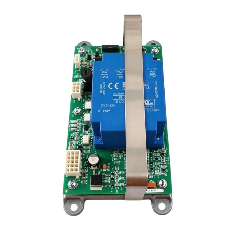
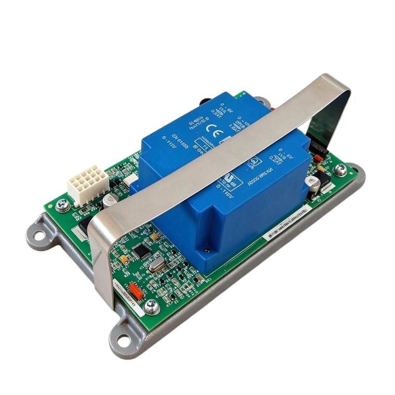
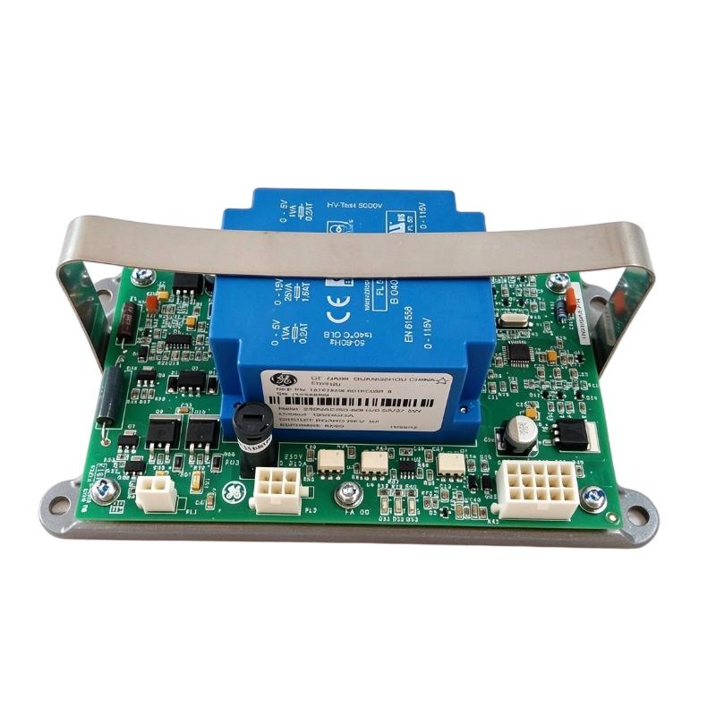
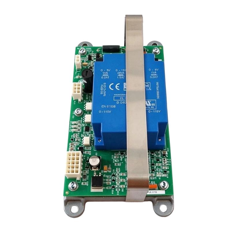
The GE 151X1225EK01PC03 Charger Board Assembly is an electronic charging circuit board associated with GE Energy’s 151X series equipment. It is designed for battery-charging applications and provides a regulated DC output for compatible charging and auxiliary power circuits.
In industrial energy systems, battery charging equipment plays an important role in maintaining the availability of backup power. Batteries may be required to support control electronics, protection circuits, monitoring equipment, and other essential functions when the primary power supply is interrupted. A charger board is therefore an important part of the overall electrical support architecture.
The 151X1225EK01PC03 is identified in product documentation and industrial spare-parts listings as a Charger Output Board. Its published electrical information identifies a 230 V AC input at 50–60 Hz and a 12 V DC output rated at up to 2 A. The input rating is approximately 52 VA.
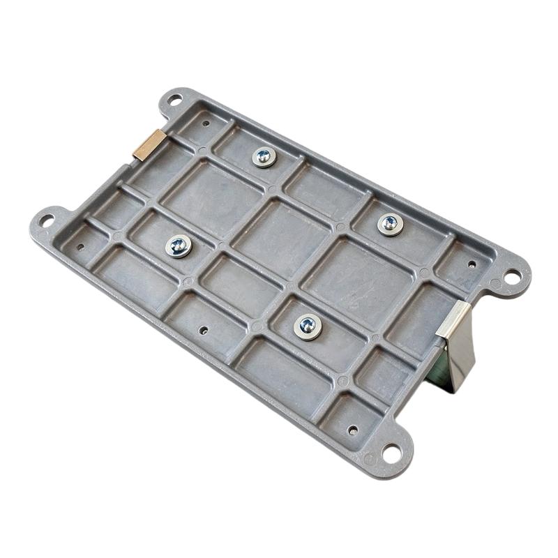
The board is associated with GE Energy equipment and is listed as part of the GE 151X Boards and Modules product range. Its physical construction includes a metal mounting backplate, electrical connectors, and circuit-board components. These features allow it to be installed as part of a compatible charging assembly.
The complete part number is important when sourcing a replacement. Similar GE charger boards may have different output ratings, connector arrangements, revisions, or application requirements. Before installation, users should compare the part number, revision, electrical ratings, connector layout, and physical mounting arrangement with the original unit.
Technical Specifications
| Parameter | Specification |
|---|---|
| Brand | GE |
| Manufacturer | General Electric / GE Energy |
| Model | 151X1225EK01PC03 |
| Product Type | Charger Board Assembly |
| Functional Description | Charger Output Board |
| Product Series | GE 151X Boards and Modules |
| AC Input Voltage | 230 V AC |
| Input Frequency | 50–60 Hz |
| DC Output Voltage | 12 V DC |
| Maximum Listed Output Current | 2 A |
| Input Rating | Approximately 52 VA |
| Board Revision Reference | Rev. 7 listed in supplier technical information |
| Mounting | Metal backplate with drilled mounting holes |
| Electrical Connections | Multiple board connectors |
| Dimensions Provided | 216 × 52 × 152 mm |
| Weight Provided | 0.55 kg |
| Typical Application | Battery charging and auxiliary DC power |
| Manufacturer | GE Energy |
Note: The electrical ratings above reflect available product-specific technical information. Confirm the actual nameplate, board revision, and associated charging assembly before installation. Dimensions and weight are the supplied listing values.
Function and Working Principle
The GE 151X1225EK01PC03 is a charger output board intended to support the conversion and regulation of electrical power for a compatible DC charging circuit.
Its operation is part of a larger charging system. The complete system may include an AC input, power-conversion circuitry, voltage regulation, current-limiting functions, battery connections, and monitoring or protection components.
1. AC Input Reception
The board’s associated charging configuration is listed with a 230 V AC input and a frequency range of 50–60 Hz.
The incoming AC supply provides the energy required by the charging circuit. The input must remain within the specified electrical limits of the complete assembly.
Incorrect supply voltage, frequency, wiring, or grounding can cause abnormal operation and may damage electronic components.
2. DC Output Provision
The published output specification is 12 V DC at up to 2 A.
This DC output can support compatible battery-charging or auxiliary power applications. The actual charging behavior depends on the complete charging circuit, battery characteristics, control components, and protection arrangements.
A 12 V output rating should not be interpreted as proof that the board can charge every 12 V battery type. Battery chemistry, charging voltage profile, current limits, temperature conditions, and charging termination requirements must all be considered.
3. Voltage Regulation
Stable DC voltage is important for battery charging and electronic power applications.
The charging assembly must maintain output conditions suitable for its intended load. Regulation performance depends on the board design and the associated power-conversion and control circuitry.
During maintenance, technicians should check the output voltage under appropriate test conditions and compare measurements with the applicable technical documentation.
4. Current Management
The listed output current is up to 2 A. This value represents an electrical rating, not a guarantee that the board will continuously deliver 2 A under every operating condition.
The actual current depends on the connected load, battery condition, temperature, and the charging system’s control and protection design.
Operating beyond the rated output can lead to excessive heating, unstable voltage, or premature component failure.
5. Electrical Connection and Mounting
The board uses multiple electrical connectors and a metal backplate with mounting holes. These features support electrical integration and mechanical installation within a compatible assembly.
Connector positions, pin assignments, and mounting details must be checked against the original equipment documentation. Similar-looking connectors should not be assumed to have identical electrical functions.
Role in Industrial Power and Automation Systems
The 151X1225EK01PC03 supports the charging and auxiliary power functions of compatible GE Energy equipment. Its role is related to maintaining DC power availability rather than performing general PLC logic processing or motor control.
Battery Charging Support
Industrial equipment may rely on batteries to maintain essential electrical functions during power interruptions. A compatible charger assembly helps maintain the battery’s charge within the limits established by the charging system.
The charger board is one component in this arrangement. Battery condition, charger control, protection devices, and wiring all influence overall performance.
Auxiliary DC Power
A regulated DC output may be used by compatible auxiliary circuits within an electrical installation. These circuits may include control electronics, monitoring devices, or other low-voltage equipment, depending on the original system design.
The board should only be connected to loads and circuits approved for its output specification.
Integration with GE Energy Equipment
The 151X1225EK01PC03 belongs to the GE 151X board and module family. Correct integration depends on the intended equipment platform, the associated charger assembly, and the board’s hardware revision.
When replacing an existing board, verify the complete part number and revision. A different charger board may have a similar physical layout but different electrical characteristics.
Support for Equipment Availability
Reliable auxiliary power is important in industrial installations where control and monitoring functions must remain available. Maintaining the charging system can therefore contribute to the operational readiness of the wider installation.
However, the charger board alone does not provide a complete backup-power system. Battery capacity, battery condition, protection, wiring, and system-level design remain essential.
Industrial Applications
The GE 151X1225EK01PC03 is relevant to compatible GE Energy battery-charging and auxiliary power arrangements.
1. Industrial Battery Charging Systems
Industrial battery systems provide stored electrical energy for equipment that requires backup or auxiliary power.
A compatible charger assembly helps maintain battery charge during normal operation so that stored energy is available when required.
2. Power Generation Equipment
Power-generation installations use auxiliary electrical systems to support control, monitoring, and protection functions.
Battery charging equipment may form part of these auxiliary systems. The 151X1225EK01PC03 should only be used in equipment configurations that specify this board or an approved equivalent.
3. Renewable Energy Equipment
Renewable energy installations may contain auxiliary DC systems that support monitoring, control, and other electrical functions.
Battery charging is one part of the broader power-management arrangement. The charger board’s actual suitability depends on the system design and the required DC output characteristics.
4. Industrial Control Power Systems
Some industrial installations use dedicated DC power circuits for control and monitoring equipment. A charger assembly may help maintain the associated battery supply.
The 151X1225EK01PC03’s 12 V DC, 2 A output specification should be checked against the load and battery requirements before it is considered for such an application.
5. Electrical Maintenance and Spare-Parts Replacement
The board may be required during maintenance of existing GE Energy equipment. Keeping an accurately identified spare can help reduce downtime when a charger output board develops a fault.
For replacement projects, the original part number, revision, connector arrangement, and electrical characteristics should be verified before procurement.
Installation and System Integration
Correct installation is necessary to protect the board and ensure reliable operation of the charging system.
1. Verify the Exact Part Number
Before installation, confirm that the replacement is marked 151X1225EK01PC03.
Check the board revision and compare it with the original component. Do not rely only on product appearance or the general description “GE charger board.”
2. Confirm Input Voltage and Frequency
The associated charging configuration is listed for 230 V AC input at 50–60 Hz.
Verify the supply conditions and the electrical requirements of the complete charger assembly before connecting power. Incorrect input conditions may damage the board or cause abnormal operation.
3. Check the DC Output Requirements
The listed output is 12 V DC at up to 2 A.
Before connecting a battery or auxiliary load, confirm that its voltage, current, charging profile, and connection requirements are compatible with the original system.
Do not connect a battery solely because its nominal voltage is 12 V. Different battery chemistries may require different charging characteristics.
4. Inspect Connectors and Wiring
Inspect all electrical connectors for corrosion, loose contacts, damaged insulation, or signs of overheating.
Verify connector orientation and pin assignments against the equipment wiring documentation. Incorrect connections may cause short circuits, reversed polarity, or damage to associated electronics.
5. Confirm Mechanical Mounting
The supplied dimensions are 216 × 52 × 152 mm, with a listed weight of 0.55 kg.
Check the board’s actual dimensions, mounting-hole positions, and backplate arrangement before installation. Ensure that the assembly is securely mounted and that wiring does not place excessive mechanical stress on the connectors.
6. Follow Electrical Safety Procedures
Isolate the AC supply and any connected battery source before removing or installing the board. Battery systems can retain hazardous energy even when the AC input is disconnected.
Follow the equipment manufacturer’s safety procedures and use appropriate protective equipment. Installation and testing should be performed by qualified personnel.
7. Test the Charging System
After installation, inspect all connections and verify the input supply before energizing the assembly.
Measure the DC output under suitable test conditions and compare the result with the applicable specification. Where permitted by the equipment procedure, verify charging behavior and check for abnormal heating, noise, or fault indications.
Record the replacement part number and revision for future maintenance.
Compatible System Components
The 151X1225EK01PC03 should be treated as a component of a compatible GE Energy charging assembly. Its operation depends on the surrounding power and battery system.
| Component | Function | Compatibility Considerations |
|---|---|---|
| AC input supply | Provides electrical energy to the charger | Confirm 230 V AC and 50–60 Hz requirements |
| Charger power-conversion circuit | Converts input power for the DC charging circuit | Must match the original GE charging assembly |
| Battery | Stores electrical energy | Confirm nominal voltage, chemistry, capacity, and charging profile |
| DC output wiring | Transfers regulated DC power | Verify conductor size, polarity, insulation, and current rating |
| Protection devices | Help protect the charging circuit | Use the protection specified for the original installation |
| Monitoring circuitry | Monitors charging or system conditions | Confirm signal and interface compatibility |
| Mounting backplate | Supports the board mechanically | Verify hole positions and assembly dimensions |
| GE Energy equipment | Provides the intended operating platform | Confirm the exact system and board revision |
These components are examples of the wider charging arrangement. They are not necessarily supplied with the 151X1225EK01PC03 board.
Alternative Models and Replacement Considerations
The GE 151X series contains multiple boards and assemblies with different electrical functions. A part from the same series should not automatically be considered a direct replacement.
| Related Part or Option | Description | Replacement Considerations |
|---|---|---|
| 151X1225EK01PC04 | Related GE battery charger assembly | Verify output rating, revision, and system compatibility |
| 151X1225EK01PC03R | Related charger card assembly listing | Confirm revision and exact electrical configuration |
| 109W6930P001 | Associated GE battery-charger part reference in industry listings | Verify cross-reference documentation before substitution |
| Original 151X1225EK01PC03 | Exact replacement part number | Preferred reference when maintaining an existing installation |
Before selecting an alternative, compare:
- Complete part number and revision.
- AC input voltage and frequency.
- DC output voltage and current.
- Connector locations and pin assignments.
- Mounting-hole positions and backplate dimensions.
- Battery type and charging requirements.
- Compatibility with the original GE Energy equipment.
- Protection and monitoring arrangements.
A replacement board with a similar description may not have the same electrical characteristics. Cross-reference information should be confirmed through the equipment documentation before installation.
Key Advantages
Defined DC Output Rating
The listed 12 V DC output and 2 A current rating provide a clear reference for evaluating compatible charging and auxiliary power applications.
Industrial Charger Application
The board is designed for use within an industrial charging arrangement rather than as a general-purpose controller or signal-processing module.
Compact Board Assembly
Its circuit-board construction and metal mounting backplate support installation within a compatible equipment assembly.
Multiple Electrical Connections
The board’s connector arrangement allows it to interface with the associated charging equipment. Correct pin identification remains essential during replacement.
GE Energy Product Identification
The complete 151X1225EK01PC03 part number helps maintenance teams identify the required spare and distinguish it from related GE charger assemblies.
Maintenance and Replacement Value
For existing installations, sourcing the correct charger output board can support repair and maintenance activities without requiring an immediate redesign of the complete charging system.
Technical FAQs
1. What is the GE 151X1225EK01PC03?
It is a GE Energy charger output board associated with the 151X series of boards and modules. It is used within compatible battery-charging equipment.
2. What is the input voltage?
The associated product specification lists a 230 V AC input.
3. What is the output voltage?
The listed DC output is 12 V DC.
4. What is the maximum listed output current?
The published output rating is up to 2 A. Actual operating current depends on the connected battery or load and the charging system’s design.
5. Is the 151X1225EK01PC03 a complete battery charger?
It is identified as a charger output board or charger board assembly. Whether it represents a complete functional charger depends on the exact assembly supplied and the equipment configuration. Confirm the included components before purchasing.
6. Can it charge any 12 V battery?
No. A 12 V nominal battery may require a specific charging voltage profile, current limit, and charging termination method. Compatibility must be confirmed for the battery chemistry and original charger design.
7. Is it compatible with other GE 151X boards?
It belongs to the GE 151X board family, but this does not mean it is interchangeable with other 151X products. Confirm the intended system, electrical ratings, connectors, and revision.
8. What should be checked before replacing the board?
Verify the complete part number, revision, input and output ratings, connector positions, wiring, and mounting arrangement. Also inspect the associated charging circuit and battery for faults that may have caused the original board to fail.
9. How should the board be stored?
Store the board in suitable electrostatic-protective packaging in a clean, dry environment. Avoid moisture, dust, conductive contamination, and mechanical impact. Follow the manufacturer’s storage recommendations where available.
10. What are the supplied dimensions and weight?
The supplied listing data gives dimensions of 216 × 52 × 152 mm and a weight of 0.55 kg. Verify these figures against the actual unit before using them for shipping or installation planning.
Procurement and Maintenance Recommendations
When sourcing the GE 151X1225EK01PC03, confirm the exact part number and revision before placing an order. Product descriptions such as “GE Charger Board” are not sufficient for reliable identification because related assemblies may have different electrical specifications.
For new, surplus, or refurbished units, request clear photographs of the front and rear of the board, connector areas, mounting backplate, and identification labels. Confirm the board’s condition and whether it has been tested.
For maintenance, inspect the board and surrounding charging equipment for loose connectors, corrosion, damaged wiring, contamination, and signs of overheating. Check the battery and associated protection components as well as the charger board itself. A battery fault or external circuit problem may cause repeated failures if it is not corrected.
Record the installed board’s part number and revision after replacement. Keep the applicable wiring diagrams and charging-system settings available for future maintenance.
Conclusion
The GE 151X1225EK01PC03 Charger Board Assembly is an industrial charger output board associated with GE Energy’s 151X product family. Its available electrical specifications identify a 230 V AC, 50–60 Hz input and a 12 V DC output rated at up to 2 A.
The board supports compatible battery-charging and auxiliary DC power arrangements. Correct part-number identification, revision verification, electrical compatibility checks, and careful installation are essential when maintaining or replacing this component in an existing GE Energy system.