

ProductPRODUCT
Featured products
Contact Us
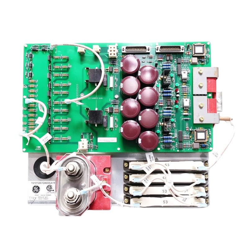
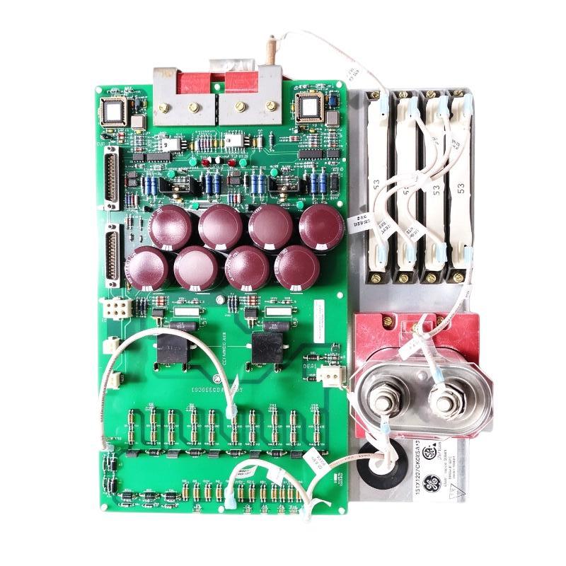
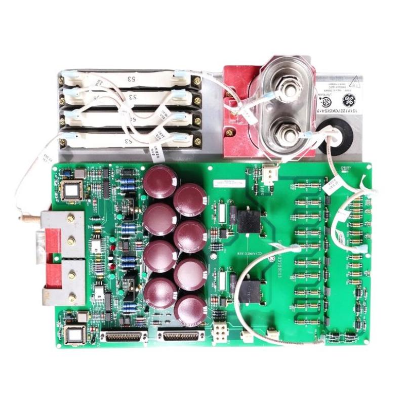
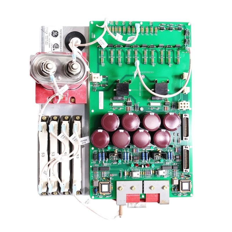
- GE
- 151X1207CK02SA01
- De-excitation Module
- USA
- 220 x 35 x 100 mm
- 0.7 kg
- Xiamen, China
- New & In Stock
- T/T, PayPal, Western Union
- 1 Year
- 1-3 Working Days
- DHL, UPS, TNT, FedEx and EMS.
- 24-Hour Service
- COO
- 5
Our advantage

Global Logistics
We have a 10-year logistics and express cooperation agreement, so our products can be shipped to any place in the world.

Brand new and original
Our products are imported in bulk from the place of origin. Because of the cooperative relationship, our products are all original and 100% new.

24-hour service
We provide 7*24 hours service to our customers. We will be there whenever you need us.

Price advantage
All our products are priced very favorably because we have our own warehouse and supply.
| Company Information | |||
| [email protected] | |||
| Mobile | +8615980777398 | ||
| +8615980777398 | |||
| 15980777398 |
Product Overview
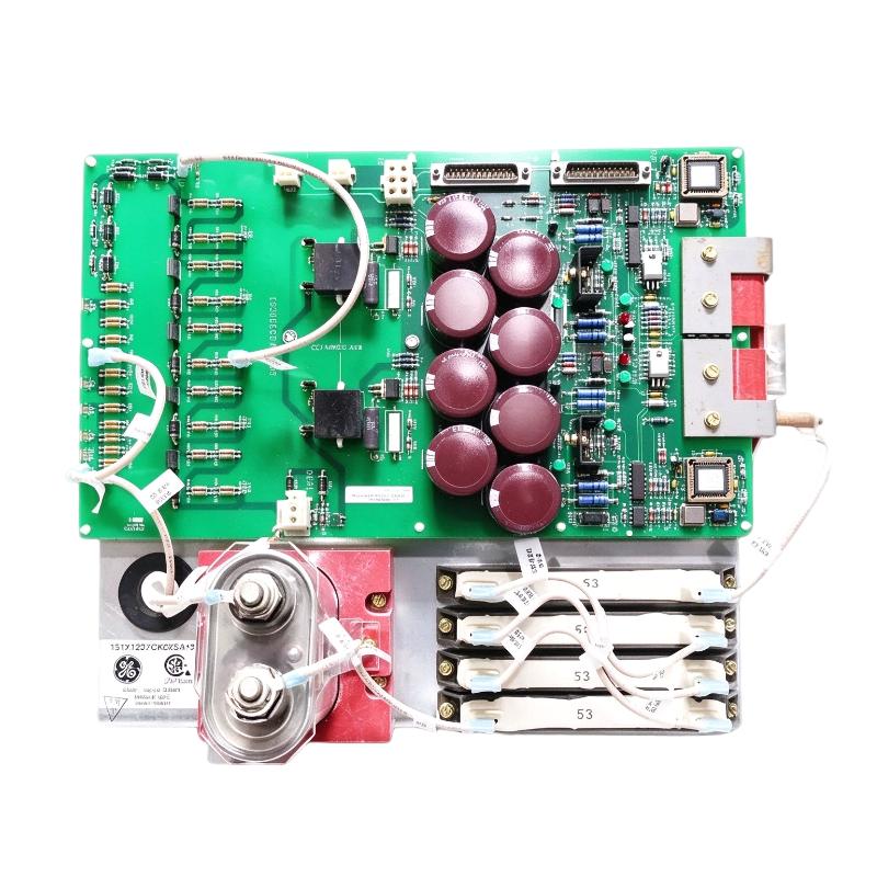
The GE 151X1207CK02SA01 De-Excitation Module is an electrical component associated with the GE EX2100 generator excitation system. It is identified in industrial spare-parts references as a 600 V/1000 V generator auxiliary de-excitation module. Its role is related to the excitation and de-excitation functions used in generator control and protection arrangements.
A generator excitation system regulates the magnetic field of a synchronous generator. During normal operation, the excitation system supplies and controls field current to maintain the required generator voltage and reactive power characteristics. When a shutdown or protection event occurs, the excitation system must also support the appropriate removal or reduction of field excitation.
De-excitation is an important part of generator protection. Depending on the generator design and system configuration, the de-excitation circuit helps reduce stored magnetic energy in the rotor field winding and brings the excitation system into a defined safe state. The exact switching arrangement and energy-dissipation method depend on the complete excitation-system design.
The 151X1207CK02SA01 is associated with GE EX2100 excitation equipment used in generator applications, including power-generation installations. It should be treated as a system-specific component rather than a general-purpose control module. Correct identification is essential because excitation-system components can have similar physical appearances while serving different electrical functions.
For maintenance and replacement projects, engineers should verify the complete part number, cabinet configuration, electrical ratings, terminal connections, and associated components before installation.
Technical Specifications
| Parameter | Specification |
|---|---|
| Brand | GE |
| Manufacturer | General Electric |
| Model | 151X1207CK02SA01 |
| Product Type | De-Excitation Module |
| Product Description | 600 V/1000 V Generator Auxiliary De-Excitation Module |
| System Association | GE EX2100 Excitation System |
| Application | Generator excitation and de-excitation circuit |
| Equipment Category | Generator excitation control component |
| Dimensions Provided | 220 × 35 × 100 mm |
| Weight Provided | 0.7 kg |
| Installation Environment | Industrial electrical control cabinet |
| Typical Industry | Power generation |
| Replacement Requirement | Verify exact part number and system configuration |
Note: The dimensions and weight are the supplied product-listing values. The precise electrical ratings, internal circuit design, and connection details should be confirmed using the original GE documentation for the installed assembly.
Function and Working Principle
The GE 151X1207CK02SA01 is associated with the de-excitation function of a generator excitation system. Understanding its application requires considering how excitation and de-excitation work together.
1. Generator Field Excitation
A synchronous generator requires a magnetic field in its rotor to generate electrical power. The excitation system supplies field current and regulates the magnetic field according to operating requirements.
During normal operation, the excitation controller monitors generator conditions and adjusts excitation as needed. This supports generator voltage regulation and coordinated operation with the wider power-generation system.
The excitation circuit may include power conversion equipment, control electronics, switching devices, protective components, and field connections.
2. De-Excitation Function
When a generator is stopped or a protective condition requires excitation to be removed, the field current must be reduced through an appropriate electrical path.
The de-excitation arrangement is designed to manage the energy stored in the rotor field winding. Depending on the system architecture, this may involve switching devices and energy-dissipation components.
The 151X1207CK02SA01 is identified as a generator auxiliary de-excitation module in EX2100-related parts references. Its exact circuit-level contribution should be confirmed from the system schematic rather than inferred from the product name alone.
3. Coordination with Generator Protection
Generator protection systems monitor electrical and mechanical operating conditions. Depending on the protection scheme, certain abnormal conditions may require the excitation system to reduce or remove field excitation.
The de-excitation circuit must operate as part of the overall protection design. Correct coordination between the excitation controller, switching devices, protective relays, and field circuit is therefore essential.
4. Electrical Switching and Energy Management
De-excitation is not simply the same as issuing a normal motor or generator stop command. The rotor field winding stores magnetic energy, and the excitation system must provide a suitable electrical path for managing that energy.
The switching and energy-dissipation arrangement depends on the generator and excitation-system design. Maintenance personnel should follow the original circuit drawings and safety procedures when inspecting or replacing associated components.
Role in the GE EX2100 Excitation System
The GE EX2100 is an excitation control platform used in generator applications. It coordinates excitation regulation, monitoring, and related control and protection functions.
The 151X1207CK02SA01 is associated with the EX2100 de-excitation arrangement and should be evaluated as part of the complete system.
1. Excitation-System Support
The module belongs to the wider generator excitation equipment architecture. Its role is related to the auxiliary de-excitation function, which operates alongside the normal field-excitation control arrangement.
2. Interaction with Power Components
Excitation systems include power components that handle field-current requirements. These may include rectifier assemblies, switching devices, reactors, resistors, fuses, and associated electrical connections.
The module must be compatible with the installed power circuit and the relevant system configuration. Component substitutions should not be based only on physical dimensions.
3. Coordination with Control Equipment
The excitation controller manages the operating sequence and monitors system conditions. De-excitation hardware must be correctly integrated with the control and protection architecture.
Before replacement, engineers should verify the relevant wiring diagrams, control signals, and equipment revisions.
4. Support for Maintenance and System Availability
Power-generation equipment often operates for extended periods. Keeping correctly identified spare components available can help maintenance teams respond to equipment faults and reduce delays during planned maintenance.
A replacement should be checked for model accuracy, physical condition, and electrical compatibility before being introduced into an operating excitation system.
Industrial Applications
The GE 151X1207CK02SA01 is associated with generator excitation equipment rather than general-purpose factory automation. Its application is therefore concentrated in power-generation and related electrical installations.
1. Thermal Power Plants
Thermal power stations use synchronous generators driven by steam turbines. The excitation system regulates generator field conditions and supports voltage control.
De-excitation equipment forms part of the wider excitation and protection arrangement. Correct maintenance of these components helps preserve the intended operation of the generator system.
2. Gas Turbine Power Plants
Gas turbine generators require excitation equipment to regulate generator voltage and coordinate electrical operation with the power network.
The GE EX2100 platform is associated with generator excitation applications. Components such as the 151X1207CK02SA01 may be relevant when maintaining compatible installations.
3. Combined-Cycle Power Stations
Combined-cycle facilities integrate gas and steam turbine generation. Their generator excitation systems are important to stable electrical operation and coordinated protection.
During maintenance, the exact excitation-system model and installed hardware configuration should be identified before spare parts are selected.
4. Industrial Captive Power Plants
Large industrial facilities may operate their own generators to support production processes. Generator excitation equipment is part of the electrical infrastructure that maintains generator voltage and supports safe operation.
Correct de-excitation-system maintenance is important because excitation equipment interacts with generator protection and shutdown procedures.
5. Generator Maintenance and Retrofit Projects
The module may be relevant to maintenance, repair, or spare-parts replacement work involving compatible GE EX2100 equipment.
Before using it in a retrofit, confirm whether the existing excitation-system design, wiring, and associated components support the proposed replacement.
Installation and System Integration
Installation or replacement of a generator de-excitation component requires qualified electrical personnel and access to the correct system documentation.
1. Verify the Complete Part Number
Confirm that the component is marked 151X1207CK02SA01. Do not rely solely on a supplier description or external appearance.
Check the equipment revision, assembly identification, and any applicable engineering changes. Similar GE part numbers may refer to different excitation-system components.
2. Review the Excitation-System Drawings
Before installation, consult the original EX2100 electrical drawings and equipment documentation.
Confirm the module’s position in the circuit, terminal identification, conductor routing, and relationship to the associated switching and protection components.
3. Apply Electrical Safety Procedures
Excitation systems may contain hazardous voltages and stored electrical energy. Isolate the relevant equipment, follow approved lockout/tagout procedures, and verify the electrical state before maintenance.
Only qualified personnel should work on generator excitation and de-excitation circuits.
4. Inspect Associated Components
Before replacing the module, inspect the surrounding equipment for signs of overheating, damaged insulation, loose terminals, contamination, or mechanical damage.
The condition of associated fuses, switching components, resistors, reactors, and wiring should also be evaluated where relevant to the circuit.
5. Confirm Mechanical Installation
The supplied dimensions are 220 × 35 × 100 mm, with a listed weight of 0.7 kg. Confirm the actual mounting arrangement and clearances against the original cabinet drawing.
Do not modify the mounting or wiring arrangement without engineering approval.
6. Verify the System After Replacement
After installation, qualified personnel should perform the inspections and tests specified by the excitation-system maintenance procedure.
Check the wiring, terminal connections, protective arrangements, and relevant control indications. Any functional testing of the de-excitation circuit must follow the approved generator and excitation-system test procedure.
Compatible System Components
The 151X1207CK02SA01 should be considered in the context of the complete GE EX2100 generator excitation system.
| Component or Equipment | Function | Integration Considerations |
|---|---|---|
| GE EX2100 Excitation System | Controls generator excitation | Verify the exact system revision and configuration |
| Excitation Controller | Regulates and monitors excitation operation | Confirm control logic and associated interfaces |
| Generator Field Circuit | Carries rotor field current | Follow the generator-specific electrical drawings |
| De-Excitation Circuit | Supports removal or reduction of field excitation | Verify the designed switching and energy-dissipation path |
| SCR or Rectifier Assembly | Converts electrical power for excitation | Confirm current, voltage, and assembly compatibility |
| De-Excitation Resistor | May dissipate stored field energy | Select only according to the original circuit design |
| Reactor or Inductor Assembly | Provides circuit-specific electrical characteristics | Verify the correct electrical rating and connection |
| Protective Devices | Detect and respond to abnormal conditions | Confirm coordination with the excitation system |
| Electrical Control Cabinet | Houses excitation and protection components | Check mounting, insulation, ventilation, and safety requirements |
The table describes related equipment categories. It does not mean that all components are supplied with the 151X1207CK02SA01.
Alternative Models and Replacement Considerations
The 151X1207CK02SA01 is a system-specific GE component. Other EX2100 de-excitation parts may look similar or belong to the same equipment family, but they should not be treated as direct substitutes without engineering confirmation.
| Related Model or Component | Description | Replacement Consideration |
|---|---|---|
| 151X1207CK02SA12 | GE de-excitation module variant | Verify electrical rating and system compatibility |
| 151X1207CK02SA14 | GE de-excitation and crowbar module | Different functional description; not automatically interchangeable |
| 151X1207CK02VA22 | GE de-excitation resistor | Related circuit component, not a module substitute |
| 151X1207DC13SA23 | EX2100 positive SCR assembly | A power component with a different function |
| 151X1207DC14SA23 | EX2100 negative SCR assembly | A power component with a different function |
| 151X1207CD15PC18 | GE 25 A, 1000 V fuse reference | Protective component, not a direct replacement |
Before selecting an alternative, compare:
- Complete catalog number and hardware revision.
- Rated voltage and current.
- De-excitation circuit function.
- Terminal arrangement and connection points.
- Mounting and mechanical dimensions.
- Compatibility with the EX2100 cabinet.
- Associated resistor, reactor, and switching arrangements.
- Original engineering drawings and approved replacement documentation.
The most important consideration is electrical and functional compatibility. A component with a similar product name or voltage description may still have a different role in the excitation circuit.
Key Advantages
Application-Specific Design
The 151X1207CK02SA01 is identified for use in the GE EX2100 generator excitation environment, making accurate model matching important for maintenance projects.
Support for De-Excitation Functions
The module is associated with the generator auxiliary de-excitation arrangement, which forms part of the wider excitation and protection architecture.
Integration with Generator Equipment
Its system association makes it relevant to power-generation installations using compatible GE excitation equipment.
Maintenance and Spare-Parts Value
Correctly identified spare modules can support maintenance planning for existing generator excitation systems.
Compact Listing Dimensions
The supplied dimensions of 220 × 35 × 100 mm and weight of 0.7 kg provide useful reference information for inventory management and preliminary logistics planning.
Technical FAQs
1. What is the GE 151X1207CK02SA01?
It is a GE component identified as a 600 V/1000 V generator auxiliary de-excitation module associated with the EX2100 excitation system.
2. What is the main application of this module?
It is associated with generator de-excitation functions in compatible GE EX2100 excitation installations. The precise circuit role should be confirmed using the original system drawings.
3. Is it a standard PLC module?
No. It is an excitation-system component rather than a general-purpose PLC input, output, or communication module.
4. What does de-excitation mean?
De-excitation refers to reducing or removing the generator’s rotor field excitation. The associated circuit manages the stored energy in the field winding according to the generator’s electrical design.
5. Can it be used in any GE EX2100 system?
Not automatically. The exact hardware revision, electrical configuration, and circuit design must be checked before installation.
6. Is it interchangeable with 151X1207CK02SA12?
Interchangeability should not be assumed. Compare the electrical ratings, function, assembly revision, and original GE documentation before selecting a substitute.
7. What should be checked before purchasing?
Verify the complete part number, nameplate or identification label, physical condition, terminal condition, and compatibility with the installed EX2100 system. For critical applications, request appropriate inspection and testing information.
8. What are the product dimensions and weight?
The supplied listing dimensions are 220 × 35 × 100 mm, and the supplied weight is 0.7 kg. Confirm these values against the physical item before shipping or installation planning.
9. Can the module be replaced while the generator is operating?
Maintenance work must follow the generator manufacturer’s safety and operating procedures. Do not assume that the component can be removed or replaced under energized conditions. Isolation and verification requirements must be determined by qualified personnel.
10. Why is the exact part number important?
Generator excitation components can have different electrical functions and ratings even when they belong to the same product family. Incorrect substitution may affect the excitation or protection circuit.
Procurement and Maintenance Recommendations
When purchasing the GE 151X1207CK02SA01, begin by confirming the full catalog number and its intended application in the GE EX2100 excitation system.
For new, surplus, or refurbished equipment, request clear photographs of the identification label, external connections, and physical condition. Confirm the hardware revision and ask whether inspection or functional test records are available.
For critical power-generation equipment, procurement should be coordinated with the plant’s electrical engineering and maintenance teams. Verify the component against the original circuit drawings and approved spare-parts list before installation.
During maintenance, inspect the module and surrounding excitation equipment for signs of overheating, contamination, loose connections, or insulation damage. Keep the equipment records, drawings, and replacement history up to date.
Do not use a related de-excitation module, resistor, or switching assembly as a substitute without confirming its function and electrical compatibility. Any replacement or testing procedure should be performed by qualified personnel following the approved generator and excitation-system instructions.
Conclusion
The GE 151X1207CK02SA01 De-Excitation Module is identified as a 600 V/1000 V generator auxiliary de-excitation component associated with the GE EX2100 excitation system. It belongs to the generator excitation and protection environment and should be selected according to the exact electrical and mechanical configuration of the installed equipment.
For power-generation maintenance and spare-parts procurement, accurate part-number verification is essential. Confirm the original system drawings, component ratings, and installation requirements before replacing or commissioning this module.