
NewsNEWCENTER
Featured products

Contact Us
Emerson KJ1501X1-BA1 Power Supply Module: Installation, Setup and Commissioning Guide
2026-11-05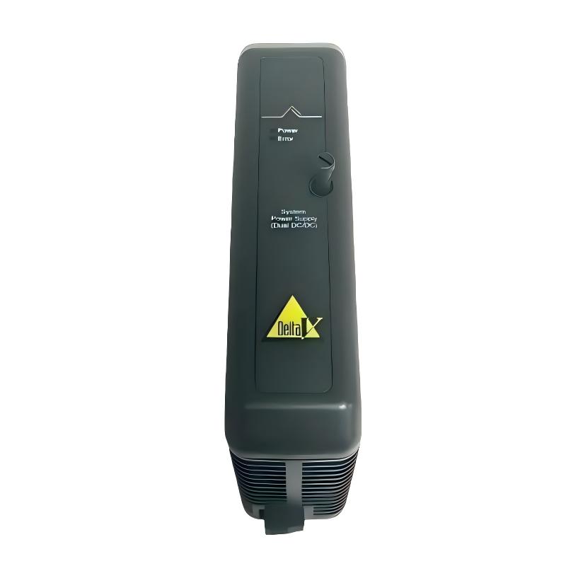
1. Product Overview
The Emerson KJ1501X1-BA1 is an industrial power supply module used in Emerson control system applications. It converts incoming AC power into regulated DC voltage rails required by electronic control equipment. Stable power delivery is essential for maintaining the operation of controllers, communication interfaces, and other system components. In industrial automation environments, power supply reliability directly affects system availability. An unsuitable input source, loose connection, excessive load, or incorrect replacement module can cause intermittent faults, controller resets, and unexpected equipment shutdowns. Proper installation and commissioning are therefore important when integrating or replacing the KJ1501X1-BA1. Before installation, engineers should verify the complete part number, product label, hardware revision, and intended system application. Power supply modules with similar model numbers may have different input arrangements, output ratings, and installation requirements.
2. Technical Specifications
The following table summarizes the available identification and electrical information for the KJ1501X1-BA1. Confirm all ratings against the module nameplate and the documentation for the installed system before applying power.
| Parameter | Specification |
|---|---|
| Manufacturer | Emerson |
| Model | KJ1501X1-BA1 |
| Product Type | Power Supply Module |
| Input Voltage | 120 VAC / 230 VAC, according to available product identification data |
| Input Current | 0.34 A at 120 VAC / 0.17 A at 230 VAC, according to available product identification data |
| DC Output Rails | +12 VDC, +5 VDC and +3.3 VDC |
| +12 VDC Output | 2.1 A maximum |
| +5 VDC Output | 2.0 A maximum |
| +3.3 VDC Output | 0.5 A maximum |
| Product Application | Industrial control system power supply |
The ratings above should not be treated as a substitute for the original equipment documentation. In particular, confirm the combined output power limit, connector assignments, protective device requirements, and permitted input configuration before installation.
3. Installation Preparation
3.1 Verify the Module Model
Check that the module label clearly identifies KJ1501X1-BA1. Do not assume that another KJ1501X1 variant is interchangeable simply because the model numbers are similar. Before installation, inspect the module for:
- Cracked or damaged housing.
- Loose, bent, or contaminated connectors.
- Signs of overheating, discoloration, or burning.
- Corrosion or moisture contamination.
- Missing labels or unreadable electrical ratings.
If the module has been stored for a long period, inspect it carefully before connecting it to the control system.
3.2 Confirm System Compatibility
Verify that the receiving equipment is designed to use the KJ1501X1-BA1. Check the system hardware documentation for the correct mounting location, connector arrangement, power distribution architecture, and load requirements. A replacement module must match the electrical and mechanical requirements of the original installation. A module that physically fits may still have an incompatible electrical configuration.
3.3 Prepare the Installation Area
The installation environment should be clean, dry, and free from excessive dust, conductive particles, and corrosive substances. Maintain sufficient ventilation around the equipment and avoid placing the power supply near heat-producing devices unless the cabinet design allows for the resulting temperature rise. Use suitable ESD protection when handling electronic assemblies. Avoid touching exposed circuit contacts and connector pins.
4. Safety Precautions Before Installation
The KJ1501X1-BA1 is associated with hazardous electrical energy. Installation and replacement should be performed only by qualified industrial electrical or automation personnel. Follow these precautions:
- Disconnect the incoming power source before installation or removal.
- Apply the site’s lockout/tagout procedure and verify that the circuit is de-energized.
- Allow sufficient time for stored electrical energy to discharge according to the equipment instructions.
- Use appropriately rated test instruments and insulated tools.
- Never connect or disconnect power wiring while energized unless the exact equipment documentation explicitly permits the operation.
- Confirm protective grounding and the required overcurrent protection.
- Follow the applicable hazardous-area installation requirements when the equipment is installed in a classified location.
Do not open or modify the module unless the manufacturer explicitly authorizes the work. Internal repair or component-level modification can compromise electrical safety and equipment reliability.
5. KJ1501X1-BA1 Installation Procedure
Step 1: Isolate the Power Supply Circuit
Identify the incoming power source and isolate it using the approved shutdown procedure. Confirm that the module and associated wiring are de-energized before proceeding. If the module is part of a larger control system, assess the effect of removing its power on controllers, I/O equipment, communication devices, and connected process operations. Coordinate the work with the control room or plant maintenance team.
Step 2: Inspect the Mounting Position
Check the designated installation position for mechanical damage, contamination, loose hardware, or signs of overheating. Make sure that the mounting surface and electrical connections are suitable for the replacement module. Do not force the module into its mounting position. Resistance during installation may indicate incorrect orientation, damaged guides, or an incompatible hardware version.
Step 3: Install the Module
Align the KJ1501X1-BA1 with the designated mounting arrangement. Insert it carefully and secure it using the hardware or retention mechanism specified for the receiving equipment. Confirm that the module is fully seated and mechanically stable. Do not apply excessive force to the housing or connectors.
Step 4: Check the Electrical Connections
Inspect the incoming power connections and associated wiring against the system wiring diagram. Confirm that the AC input voltage matches the module’s nameplate rating and that the correct terminals are used. Pay particular attention to:
- Input voltage selection and supply compatibility.
- Correct line, neutral, and protective earth connections where applicable.
- Connector condition and terminal tightness.
- Correct polarity on any DC-side connections.
- Load requirements and the permitted output current.
Never determine terminal assignments from physical appearance alone. Use the correct wiring documentation for the exact hardware revision.
Step 5: Complete the Pre-Power Inspection
Before restoring power, check that all connections are secure and that no tools, loose fasteners, or foreign objects remain inside the equipment enclosure. Verify that the load connected to each DC output rail is within the permitted rating. Also confirm that the combined output power does not exceed the module’s specified limit.
6. Power-Up and Commissioning
6.1 Restore the Input Power
After completing the installation checks, restore power according to the plant’s approved commissioning procedure. Observe the module and the receiving equipment for abnormal indications, unusual noise, overheating, or unexpected shutdowns. If the system does not start normally, isolate the power again before inspecting wiring or connections.
6.2 Verify the DC Output Rails
Where the system design provides safe and approved test points, use a properly rated digital multimeter to verify the DC outputs. The available product identification data lists the following output rails:
| Output Rail | Maximum Output Current | Inspection Focus |
|---|---|---|
| +12 VDC | 2.1 A | Voltage stability and connected load |
| +5 VDC | 2.0 A | Voltage stability and connected load |
| +3.3 VDC | 0.5 A | Voltage stability and connected load |
Use the manufacturer’s specified voltage tolerance when evaluating the measured values. Do not probe exposed terminals unless the test procedure identifies them as approved measurement points.
6.3 Check the Connected Equipment
After confirming that the power rails are operating correctly, inspect the status of the powered control equipment. Check for controller startup errors, communication interruptions, abnormal I/O indications, and power-related alarms. A successful power supply startup does not automatically confirm that the entire control system is healthy. The connected equipment should complete its own startup and diagnostic sequence.
6.4 Record Commissioning Results
Document the installation and commissioning results for future maintenance. A useful commissioning record includes:
- Module model and hardware identification.
- Installation date and equipment location.
- Incoming power measurement.
- Verified DC output measurements.
- Connected load information.
- Controller and system diagnostic status.
- Any alarms or corrective actions.
7. Integration in Industrial Control Systems
The KJ1501X1-BA1 supplies DC power to electronic equipment through the designated power distribution arrangement. Stable DC rails help control equipment maintain predictable operating conditions and reduce the risk of resets caused by unstable supply voltage. When integrating the module into an existing system, engineers should evaluate the complete power distribution path rather than examining the power supply alone. This includes the incoming AC circuit, protective devices, wiring, connectors, output loads, and grounding arrangement. The load calculation should consider both the individual output current limits and the combined power capacity. A system may exceed the permitted total output even when no individual rail appears to exceed its own current rating. For replacement projects, record the original module configuration before removal. Confirm that the replacement has the same electrical characteristics and is approved for the intended installation.
8. Maintenance and Reliability Recommendations
Routine maintenance can help identify developing power supply problems before they affect production. Recommended inspection activities include:
- Check the module and surrounding wiring for discoloration or overheating.
- Inspect connectors for looseness, corrosion, or contamination.
- Review system alarms and controller restart records.
- Check output voltage when abnormal equipment behavior is reported.
- Confirm that cabinet ventilation remains unobstructed.
- Review the connected load after system expansions or equipment modifications.
Avoid unnecessary removal or repeated reconnection of the module. Frequent handling can increase the risk of connector damage and electrostatic discharge.
9. Frequently Asked Questions
What is the Emerson KJ1501X1-BA1?
The KJ1501X1-BA1 is an Emerson industrial power supply module. Its identified DC output rails include +12 VDC, +5 VDC, and +3.3 VDC for compatible electronic equipment.
What should be checked before installing the KJ1501X1-BA1?
Verify the complete model number, input voltage, output ratings, mounting arrangement, connector assignments, and compatibility with the receiving equipment. Also inspect the module for physical damage.
Can the module be replaced while the system is powered?
Do not assume that live replacement is permitted. Isolate the power and follow the equipment-specific removal and installation instructions unless the exact system documentation explicitly authorizes another procedure.
How can engineers check whether the power supply is working correctly?
Qualified personnel can inspect the module, verify the incoming supply, and measure the DC output rails at approved test points. They should also review the startup and diagnostic status of the connected equipment.
What can cause unstable output voltage?
Potential causes include an unsuitable input supply, excessive load, loose connections, damaged wiring, poor ventilation, or an internal module fault. Check the complete power distribution path before deciding that the module needs replacement.
Can another KJ1501X1 model be used as a replacement?
Not automatically. Different suffixes may indicate different input and output configurations. Confirm electrical ratings, mechanical compatibility, and system approval before selecting an alternative.
10. Conclusion
The Emerson KJ1501X1-BA1 Power Supply Module is an important component in industrial control power distribution. Correct installation, careful electrical verification, and appropriate commissioning procedures help maintain stable power delivery to connected automation equipment. For maintenance teams, the most important steps are to verify the exact module variant, isolate power before handling, follow the correct wiring documentation, respect individual and combined output limits, and confirm normal operation after startup. These practices help reduce installation errors, prevent avoidable equipment interruptions, and support long-term reliability in industrial automation systems.
Technical Summary
The KJ1501X1-BA1 should be installed only in an approved system configuration. Before commissioning, verify its nameplate ratings, incoming supply, output rails, connected loads, and equipment compatibility. Always follow the applicable Emerson hardware instructions and site electrical safety procedures.