

ProductPRODUCT
Featured products
Contact Us
- Woodward
- 8440-1925
- Generator Set Controller
- USA
- 280 x 60 x 150 mm
- 1.81 kg
- Xiamen, China
- New & In Stock
- T/T, PayPal, Western Union
- 1 Year
- 1-3 Working Days
- DHL, UPS, TNT, FedEx and EMS.
- 24-Hour Service
- COO
- 5
Our advantage

Global Logistics
We have a 10-year logistics and express cooperation agreement, so our products can be shipped to any place in the world.

Brand new and original
Our products are imported in bulk from the place of origin. Because of the cooperative relationship, our products are all original and 100% new.

24-hour service
We provide 7*24 hours service to our customers. We will be there whenever you need us.

Price advantage
All our products are priced very favorably because we have our own warehouse and supply.
| Company Information | |||
| [email protected] | |||
| Mobile | +8615980777398 | ||
| +8615980777398 | |||
| 15980777398 |
Product Overview
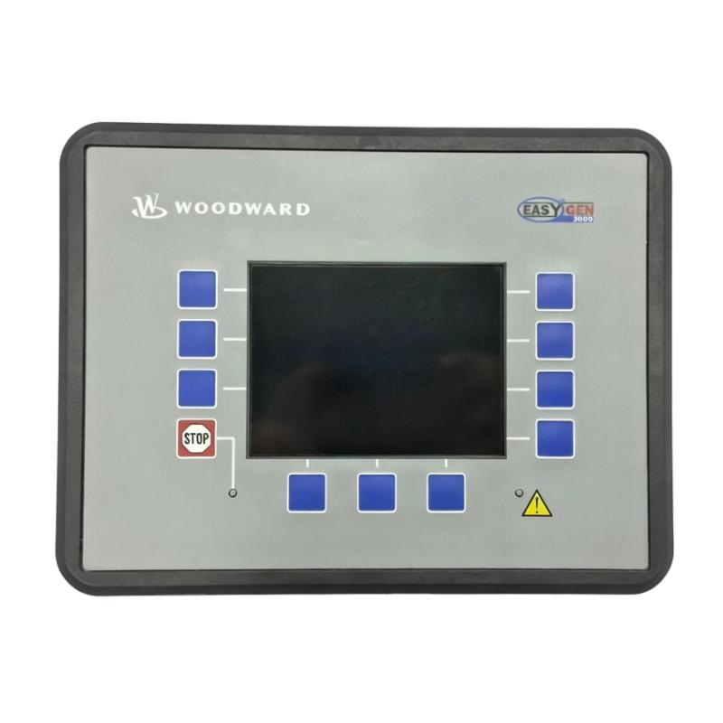
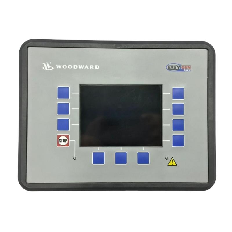
The Woodward 8440-1925 Generator Set Controller is an industrial generator management and control device belonging to the easYgen-3000 series. Specifically identified with the easYgen-3200-5-P2 configuration, it is designed for monitoring and controlling generator sets in industrial power generation systems.
Generator set controllers coordinate the operation of the engine, alternator, circuit breakers, and associated electrical equipment. They monitor operating conditions, manage start and stop sequences, display alarms, and support generator protection. In applications involving multiple generators, advanced controller functions can also support synchronization and load sharing.
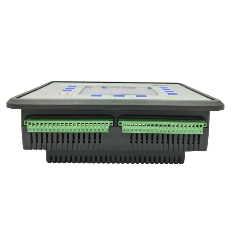
The 8440-1925 is a front-panel-mounted controller with an integrated display and operator interface. Its configuration includes 5 A current transformer (CT) inputs, extended I/O capabilities, and PID control functions. These features make it suitable for generator installations that require detailed electrical measurements, configurable control logic, and coordinated operation.
The controller can be incorporated into industrial generator panels, standby power systems, and power generation facilities. Depending on the application configuration, it can participate in generator synchronization, load sharing, mains monitoring, and automatic operating sequences.
For maintenance and replacement projects, the complete part number is important. The 8440-1925 should not be treated as interchangeable with every easYgen-3000 controller because different models may have different CT input ratings, mounting arrangements, I/O configurations, and control functions.
Technical Specifications
| Parameter | Specification |
|---|---|
| Brand | Woodward |
| Model | 8440-1925 |
| Product Series | easYgen-3000 |
| Controller Type | easYgen-3200-5-P2 |
| Product Category | Generator Set Controller |
| Application | Generator and engine control |
| Mounting Type | Front-panel mounting |
| Operator Interface | Integrated display and softkeys |
| Current Transformer Input | 5 A |
| I/O Configuration | Extended I/O |
| Control Functions | PID control functions |
| Supply Voltage | 12/24 V DC |
| Supply Operating Range | 8–40 V DC |
| Measuring Frequency | 50/60 Hz system applications; controller measuring range depends on configuration |
| Accuracy Class | Class 0.5, as listed in product data |
| Ambient Humidity | Up to 95%, non-condensing |
| Dimensions Provided | 280 × 60 × 150 mm |
| Weight Provided | 1.81 kg |
| Typical Application | Generator control, monitoring, and power management |
Note: The supplied dimensions are retained as listing information. Available product data for the 8440-1925 gives front-panel dimensions of approximately 282 × 216 × 96 mm. Verify the actual unit and dimensional drawing before using the supplied dimensions for panel design.
Function and Working Principle
The Woodward 8440-1925 manages generator operation by receiving electrical measurements and equipment status signals, processing configured control logic, and issuing commands to associated engine and generator equipment.
It acts as a central control component within a generator system. Its functions depend on the selected application, connected devices, and configured parameters.
1. Generator Electrical Measurement
The controller monitors electrical operating conditions using signals from the generator and associated instrument transformers.
Typical measurements used in generator management include:
- Generator voltage.
- Generator current.
- Generator frequency.
- Active power.
- Reactive power.
- Power factor.
- Phase-related electrical values.
The 8440-1925 is a 5 A CT input version. Current transformer ratios must be configured correctly so that the controller can interpret measured current and calculate relevant electrical quantities accurately.
Incorrect CT wiring, polarity, or ratio settings can result in inaccurate measurements and unreliable protection functions.
2. Engine and Generator Control
A generator set consists of an engine or other prime mover coupled to an alternator. The controller coordinates operating sequences and monitors relevant engine and generator conditions.
Depending on the application configuration, control functions can include:
- Engine start and stop sequencing.
- Generator operating-mode management.
- Circuit-breaker control.
- Generator status monitoring.
- Alarm handling.
- Operating-condition supervision.
The controller works with external engine control equipment and generator switching devices. It does not replace the engine’s independent mechanical and safety protection systems.
3. Synchronization Control
In installations where generators operate in parallel, synchronization is an important function.
Before a generator is connected to an energized busbar, its voltage, frequency, phase sequence, and phase angle must satisfy the applicable synchronization conditions.
A suitable easYgen-3000 application can coordinate synchronization functions and associated breaker commands. This allows generators to connect to a common busbar under controlled conditions.
The exact synchronization configuration must be established according to the generator system design and the installed controller options.
4. Load Sharing and Power Management
When multiple generators operate together, the electrical load must be distributed appropriately among the available units.
Load-sharing functions help coordinate generator output according to configured control strategies. This can support stable parallel operation and reduce the risk of one generator carrying an unsuitable proportion of the total load.
Depending on the system design, generator controllers may also support load-dependent starting and stopping, allowing generator capacity to respond to changing demand.
5. PID Control Functions
The 8440-1925 configuration is identified with PID control functions. Proportional-integral-derivative control is commonly used to regulate process variables by comparing a measured value with a target value and adjusting a control output.
In generator applications, configured control loops may be used for relevant power-management or process-control tasks.
PID performance depends on the selected control function, sensor signals, parameter settings, and characteristics of the controlled equipment. Appropriate commissioning is necessary to avoid unstable or excessive control responses.
6. Alarm and Event Management
Generator systems require continuous monitoring because abnormal operating conditions can affect power availability and equipment safety.
The easYgen-3000 family supports alarm and event-related functions. Depending on the configuration, alarms may relate to generator electrical conditions, engine operation, mains conditions, or system status.
Alarm records help operators identify abnormal events and provide maintenance personnel with useful diagnostic information.
Role in Industrial Power Generation Systems
The 8440-1925 can serve as a central controller in a generator panel. It receives measurement and status signals, processes control logic, and coordinates connected equipment.
Generator Control Panel Integration
The controller is designed for front-panel installation. Its display and operator interface allow personnel to view operating information and interact with the generator control system.
The controller is typically connected to:
- Generator voltage measurement circuits.
- Current transformers.
- Engine control equipment.
- Generator circuit breakers.
- Digital input and output circuits.
- Alarm and indication devices.
- Communication networks, where configured.
The panel design must account for electrical isolation, signal wiring, grounding, and the manufacturer’s mounting requirements.
Engine Control Integration
A generator controller needs information from the engine system to coordinate starting, running, and stopping.
Signals may include engine speed, running status, oil pressure, coolant temperature, and fault indications, depending on the engine and interface arrangement.
The 8440-1925 should be configured to work with the actual engine-control architecture. Wiring and signal definitions must be checked before commissioning.
Generator Protection Coordination
Generator protection is essential for maintaining reliable power generation and preventing equipment damage.
The broader easYgen-3000 control family provides generator and engine monitoring and protection functions. Depending on the selected application and configuration, these may include voltage, frequency, overload, reverse-power, and other protective functions.
Protection settings must be coordinated with generator ratings, circuit-breaker characteristics, and the site’s protection philosophy. Independent protection devices may still be required by the system design and applicable standards.
Parallel Generator Operation
In facilities with multiple generator sets, controllers can coordinate synchronization and load-sharing functions.
This arrangement is useful where power demand varies or where a facility needs several generators to operate together. Each generator must be correctly configured, and the communication and control architecture must be designed for the intended operating mode.
Industrial Applications
1. Industrial Standby Power Systems
Manufacturing facilities often use standby generators to maintain essential operations during utility interruptions.
The 8440-1925 can be used in a suitable generator control panel to monitor generator conditions, coordinate operating sequences, and support automatic standby power arrangements.
Typical applications include factories, warehouses, production plants, and industrial facilities with critical electrical loads.
2. Power Generation Plants
Generator installations require reliable measurement, control, and protection. The controller can be incorporated into generator systems where operators need to monitor electrical conditions and manage generator operation.
The exact control strategy depends on the generator type, prime mover, electrical connection, and plant automation design.
3. Multiple Generator Systems
Facilities that operate multiple generator sets may need synchronization and load-sharing functions.
The easYgen-3000 family supports applications involving generator parallel operation. Properly configured systems can coordinate generator connection and distribute load according to the selected operating strategy.
Examples include industrial power stations, large commercial facilities, and distributed power installations.
4. Combined Heat and Power Systems
Combined heat and power (CHP) installations produce electrical power while recovering useful heat from the prime mover.
Generator control is an important part of these systems because electrical output must be coordinated with the plant’s operating requirements.
The 8440-1925 may be used in a compatible generator-control arrangement where its electrical measurement and control capabilities meet the application requirements.
5. Marine and Remote Power Systems
Marine and remote installations may depend on generator sets for continuous or standby electrical power.
Generator controllers help monitor operating conditions and coordinate generator operation. Suitability for a particular marine installation must be checked against the applicable environmental, classification, and certification requirements.
6. Industrial Utility and Auxiliary Power
Industrial sites may use generator sets to supply auxiliary equipment, emergency systems, or isolated electrical loads.
The controller can support monitoring and control within a properly engineered generator panel, helping operators manage the power source and identify abnormal operating conditions.
Installation and System Integration
Correct installation and commissioning are essential for reliable generator control.
1. Verify the Controller Model
Before installation, confirm that the device is the Woodward 8440-1925 and that its configuration matches the generator system.
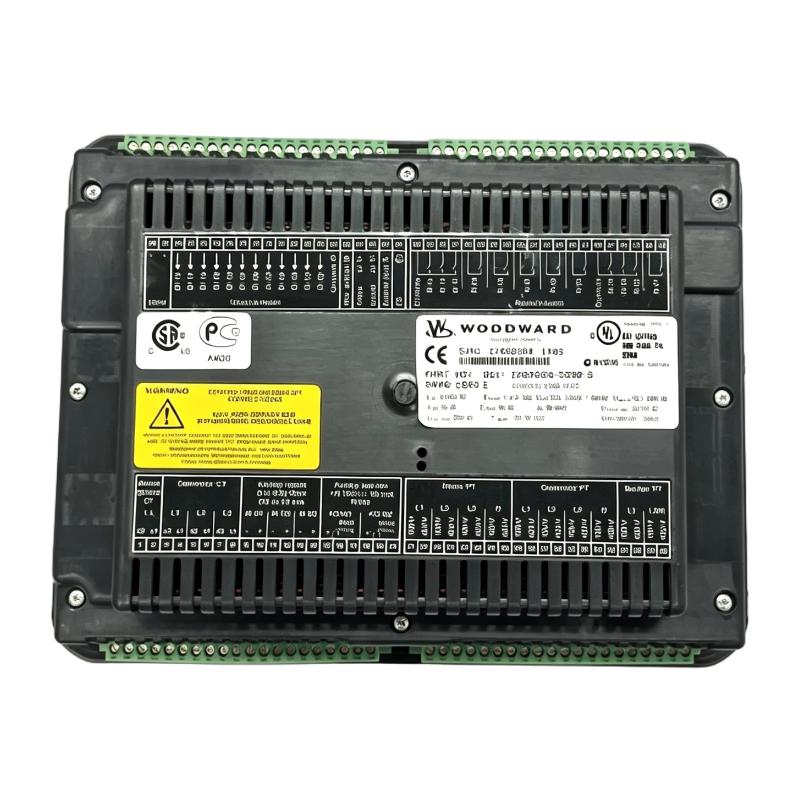
Check the nameplate, hardware revision, software version, CT input rating, and available I/O. A different easYgen-3000 model may have different electrical connections or application functions.
2. Panel Mounting
The 8440-1925 is a front-panel-mounted controller with an integrated display.
The supplied dimensions are 280 × 60 × 150 mm, but available product information lists different front-panel dimensions. Use the correct manufacturer’s dimensional drawing to determine the panel cutout, mounting depth, clearances, and fastening arrangement.
Allow sufficient space for wiring, connector access, ventilation, and maintenance.
3. Power Supply Connection
The controller is designed for a 12/24 V DC supply, with a documented operating range of 8–40 V DC.
Verify the actual supply voltage, polarity, grounding arrangement, and available current capacity before connecting the unit.
For generator applications, the DC control supply should be designed to remain stable during engine cranking and other transient conditions.
4. Current Transformer Wiring
The 8440-1925 uses 5 A CT inputs. Confirm the current transformer secondary rating and ratio before connecting the measurement circuits.
Important checks include:
- Correct CT phase assignment.
- Correct polarity.
- Appropriate terminal connections.
- Correct CT ratio settings.
- Secure wiring and suitable terminal protection.
Current transformer secondary circuits must be handled carefully. Never leave an energized CT secondary open-circuit. Follow the applicable electrical safety procedures when installing or servicing CT wiring.
5. Voltage Measurement Wiring
Generator and mains voltage signals must be connected according to the controller’s wiring instructions.
Confirm the system voltage, phase configuration, frequency, and voltage transformer ratios where applicable.
Incorrect voltage measurement wiring can affect generator measurement, synchronization, and protection functions.
6. Configure Control Parameters
Commissioning personnel should configure the controller according to the actual generator and engine specifications.
Relevant settings may include:
- Generator rated voltage.
- Rated frequency.
- Current transformer ratio.
- Generator power rating.
- Engine operating parameters.
- Start and stop conditions.
- Alarm thresholds.
- Circuit-breaker logic.
- Synchronization settings.
- Load-sharing parameters.
- PID control settings.
The configuration should be tested under controlled conditions before the generator is placed into normal service.
7. Functional Testing
After wiring and parameter configuration, perform functional checks according to the commissioning plan.
Test measurement accuracy, engine start and stop commands, alarm indications, breaker control, and relevant protection functions.
For parallel generator applications, synchronization and load-sharing tests should be completed under controlled operating conditions by qualified personnel.
Compatible System Components
The Woodward 8440-1925 works as part of a larger generator control system. The following components may be used in a compatible installation.
| Component | Function | Integration Considerations |
|---|---|---|
| Diesel or gas engine | Provides mechanical power to the alternator | Confirm engine interface and control signals |
| Alternator | Generates electrical power | Verify voltage, frequency, current, and power ratings |
| Current transformers | Provide generator current measurement | The 8440-1925 uses 5 A CT inputs |
| Voltage transformers | Provide voltage measurement where required | Confirm voltage ratio and wiring arrangement |
| Engine control unit | Manages engine operating functions | Check interface signals and control responsibilities |
| Generator circuit breaker | Connects or isolates the generator | Verify breaker ratings and control logic |
| DC power supply or battery system | Supplies controller and auxiliary circuits | Confirm 12/24 V DC compatibility and transient performance |
| Operator alarm devices | Provide audible or visual warnings | Configure according to alarm logic |
| PLC | Coordinates plant-level automation | Define signal exchange and operating responsibilities |
| Communication equipment | Supports data exchange with other systems | Confirm the actual communication interfaces and configuration |
The components listed above are examples of equipment used in generator control systems. They are not necessarily supplied with the 8440-1925 controller.
Alternative Models and Replacement Considerations
The 8440-1925 belongs to the Woodward easYgen-3000 family. Other models in this family may share certain functions, but they should not be assumed to be direct replacements.
| Model or Product Family | General Description | Replacement Considerations |
|---|---|---|
| Woodward 8440-1922 | easYgen-3000 series controller | Verify CT input and application configuration |
| Woodward 8440-1923 | easYgen-3000 series controller | Compare current measurement and I/O configuration |
| Woodward 8440-1924 | easYgen-3000 series controller | Confirm exact hardware and application differences |
| Woodward 8440-1930 series | Cabinet-back-mounted easYgen controller configuration | Mounting and display arrangements may differ |
| Woodward 8440-1931 series | easYgen-3000 controller configuration | Check I/O, measurement, and application requirements |
| Current Woodward easYgen controllers | Newer generator control options | May require wiring changes and application reconfiguration |
Before selecting a replacement, compare:
- Full Woodward part number.
- Hardware revision and software version.
- CT input rating.
- Voltage measurement arrangement.
- Front-panel or cabinet-back mounting.
- Display and operator interface.
- Digital and analog I/O.
- Communication interfaces.
- Generator protection functions.
- Synchronization and load-sharing requirements.
- Existing panel wiring and control logic.
A replacement controller may require changes to the panel cutout, terminal wiring, configuration files, or generator operating logic. A qualified engineer should review the complete system before substitution.
Key Advantages
Integrated Generator Control
The controller combines generator monitoring and control functions within a single operator-facing device, helping organize generator operation and system supervision.
5 A CT Input Configuration
The 5 A CT input version supports current measurement from compatible current transformers. Correct ratio configuration is necessary for accurate measurement.
Extended I/O Capability
The specified configuration includes extended I/O functions, providing additional flexibility for generator status signals, control commands, and application-specific logic.
PID Control Functions
PID capabilities support configured control applications that require regulation of measured process variables.
Operator Display
The front-panel display provides an interface for viewing generator information, alarms, and operating conditions.
Support for Advanced Generator Applications
The easYgen-3000 family supports advanced generator-control functions, including synchronization and load-sharing applications when configured with the appropriate system components.
Industrial Power Management
The controller can be integrated into industrial generator panels and power management systems where reliable monitoring and coordinated operation are required.
Technical FAQs
1. What is the Woodward 8440-1925?
The Woodward 8440-1925 is an easYgen-3000 series generator set controller, identified with the easYgen-3200-5-P2 configuration. It is used for generator monitoring, control, and power management.
2. What is the difference between the 8440-1925 and other easYgen-3000 models?
Models within the easYgen-3000 family can differ in CT input rating, I/O configuration, mounting arrangement, display, and application functions. The complete part number should be checked before selecting a replacement.
3. What is the CT input rating of the 8440-1925?
The 8440-1925 is identified as a 5 A CT input version. The connected current transformers and controller settings must be matched correctly.
4. What power supply does the controller use?
The controller is designed for a 12/24 V DC supply, with a documented operating range of 8–40 V DC. Confirm the electrical specifications for the exact hardware revision before installation.
5. Can the 8440-1925 control multiple generators?
The easYgen-3000 family supports generator synchronization and load-sharing applications. The number of generators and the exact operating arrangement depend on the selected application, controller configuration, and communication architecture.
6. Does the controller support PID functions?
Yes. The 8440-1925 is identified with PID control functions. The available control loops and their application depend on the configured system and software.
7. Can it communicate with a PLC?
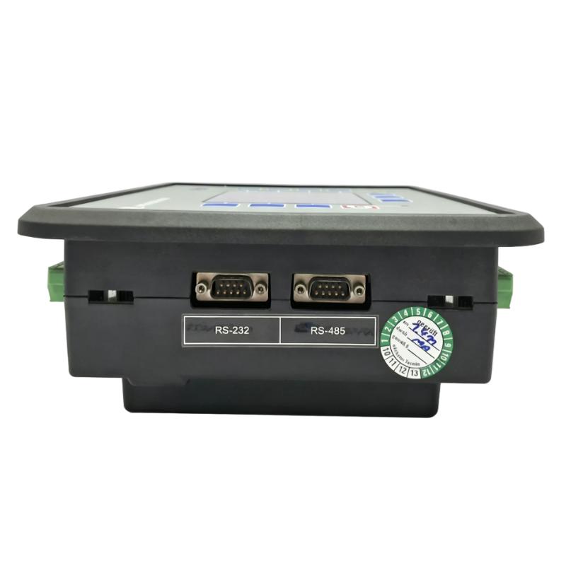
The easYgen-3000 family supports communication options used in industrial control applications, including Modbus-related interfaces in documented configurations. Confirm the communication ports and protocol settings of the exact 8440-1925 unit before designing the PLC connection.
8. What should be checked before purchasing a replacement?
Check the complete part number, hardware revision, software version, CT input rating, I/O configuration, display arrangement, and mounting dimensions. Also verify that the replacement supports the generator’s protection and synchronization requirements.
9. Is the 8440-1925 discontinued?
Some industrial spare-parts listings identify the model as discontinued by the manufacturer. Buyers should confirm its current lifecycle and availability directly through Woodward or an authorized representative.
10. Why should the dimensions be verified?
Available product information lists front-panel dimensions of approximately 282 × 216 × 96 mm, which differ from the supplied listing dimensions of 280 × 60 × 150 mm. The figures may describe different measurement references or configurations. Always use the actual unit and its dimensional drawing for panel design.
Procurement and Maintenance Recommendations
When purchasing the Woodward 8440-1925, confirm the complete part number and verify that the controller matches the intended generator application. Pay particular attention to the 5 A CT input configuration, mounting arrangement, I/O functions, display, and software compatibility.
For used or refurbished equipment, request clear photographs of the product label, front display, rear terminals, and connectors. Ask for information about the hardware revision, software version, previous operating condition, and available functional testing.
During maintenance, inspect the controller’s connectors, terminal wiring, DC supply, CT circuits, and voltage measurement connections. Review alarm records and investigate recurring faults rather than simply resetting them.
Keep a backup of controller parameters and document any changes made during commissioning or troubleshooting. This information can help reduce downtime if the controller needs to be replaced.
For generator systems operating in parallel, maintenance should also include checks of synchronization settings, load-sharing configuration, communication connections, and breaker-control logic. Testing should be performed under controlled conditions by qualified personnel.
Conclusion
The Woodward 8440-1925 easYgen-3200-5-P2 Generator Set Controller is designed for industrial generator monitoring, control, and power management. Its 5 A CT input configuration, extended I/O capabilities, PID functions, and front-panel operator interface make it suitable for appropriately engineered generator control systems.
The controller can support applications involving generator measurement, engine coordination, alarm management, synchronization, and load-sharing strategies. For procurement and replacement projects, verifying the exact part number, CT rating, hardware configuration, and mounting dimensions is essential to maintaining reliable generator operation.