

ProductPRODUCT
Featured products
Contact Us
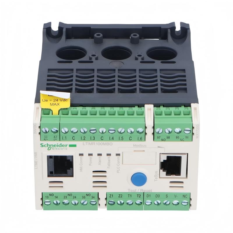
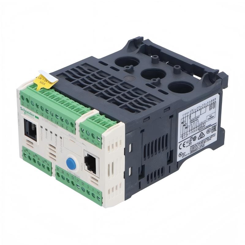
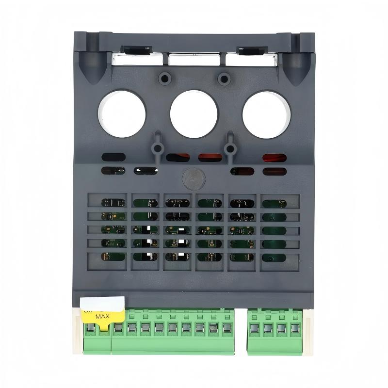
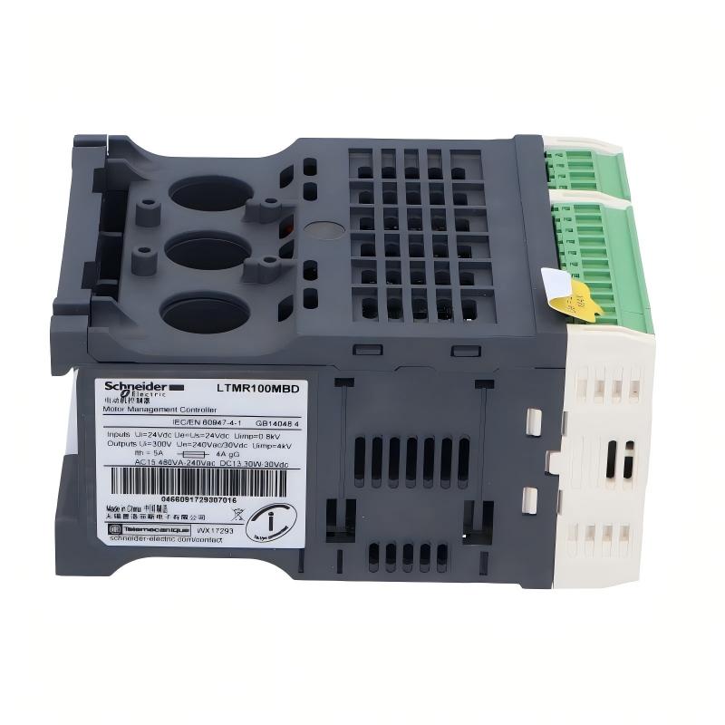
- Schneider
- LTMR100MBD
- Motor Controller
- France
- 91 x 61 x 122.5 mm
- 0.53 kg
- Xiamen, China
- New & In Stock
- T/T, PayPal, Western Union
- 1 Year
- 1-3 Working Days
- DHL, UPS, TNT, FedEx and EMS.
- 24-Hour Service
- COO
- 8
Our advantage

Global Logistics
We have a 10-year logistics and express cooperation agreement, so our products can be shipped to any place in the world.

Brand new and original
Our products are imported in bulk from the place of origin. Because of the cooperative relationship, our products are all original and 100% new.

24-hour service
We provide 7*24 hours service to our customers. We will be there whenever you need us.

Price advantage
All our products are priced very favorably because we have our own warehouse and supply.
| Company Information | |||
| [email protected] | |||
| Mobile | +8615980777398 | ||
| +8615980777398 | |||
| 15980777398 |
Product Overview
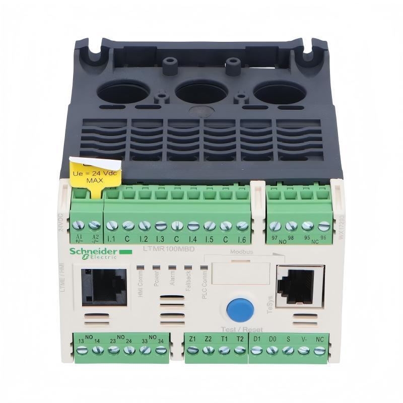
The Schneider Electric LTMR100MBD TeSys T Motor Controller is an intelligent motor management device designed for monitoring, controlling, and protecting low-voltage industrial motors. It belongs to the TeSys T motor management system and combines electrical measurement, motor protection, diagnostic information, and communication capabilities in a compact controller.
Unlike a conventional motor starter or contactor, the LTMR100MBD provides more comprehensive information about motor operating conditions. It can monitor current-related parameters, detect abnormal operating conditions, and communicate motor status and diagnostic information to a programmable logic controller (PLC) or supervisory control system through Modbus communication.
The LTMR100MBD uses a 24 V DC control supply and supports a current measurement range of 5–100 A. It provides six logic inputs and three logic outputs, allowing it to participate in industrial control sequences and exchange operating signals with external equipment. Its Modbus interface uses a two-wire RS-485 connection, supporting integration with compatible automation controllers and monitoring systems.
The controller is suitable for industrial applications where motor availability, electrical protection, and operating-condition monitoring are important. Typical applications include pumps, fans, conveyors, compressors, and general manufacturing machinery, provided that the complete motor protection system is correctly selected and configured.
The LTMR100MBD is a motor management controller rather than a standalone power drive. It does not regulate motor speed in the same way as a variable frequency drive. Instead, it monitors and manages motor operation in coordination with appropriate switching equipment, current measurement arrangements, and control logic.
The model is now a legacy product, so procurement and replacement projects should confirm its availability and compatibility with the installed motor management system.
Technical Specifications
| Parameter | Specification |
|---|---|
| Brand | Schneider Electric |
| Product Series | TeSys T |
| Model | LTMR100MBD |
| Product Type | Motor Management Controller |
| Main Application | Motor monitoring, control, and protection |
| Control Supply Voltage | 24 V DC |
| Supply Voltage Limits | 20.4–26.24 V DC |
| Current Measurement Range | 5–100 A |
| Communication Protocol | Modbus |
| Physical Communication Interface | Two-wire RS-485 |
| Communication Connection | RJ45-style port and terminal-block connection options |
| Logic Inputs | 6 |
| Logic Outputs | 3 |
| Logic Output Arrangement | Relay outputs, according to the product configuration |
| Rated Insulation Voltage | Up to 690 V, subject to applicable standards and circuit |
| Protection Functions | Motor overload, phase failure, phase imbalance, and other configured protection functions |
| Mounting | DIN rail or panel mounting, subject to installation requirements |
| Protection Rating | IP20 |
| Dimensions Provided | 91 × 61 × 122.5 mm |
| Weight Provided | 0.53 kg |
| Product Lifecycle | Legacy model; verify current commercial status |
| Typical Integration | PLC, motor starter, contactor, and industrial monitoring system |
Note: Verify the controller’s nameplate, wiring diagram, and current manufacturer’s documentation before installation. The current measurement range describes the controller’s application range and should not be interpreted as the current rating of every connected motor or switching component.
Function and Working Principle
The LTMR100MBD operates as the monitoring and protection component of a motor management system. It receives electrical measurements and control signals, evaluates the motor’s operating condition, and provides protection responses or status information according to its configuration.
1. Motor Current Monitoring
Motor current is an important indicator of operating conditions. Changes in current may result from variations in mechanical load, phase-related problems, starting conditions, or abnormal motor operation.
The LTMR100MBD supports current measurement over a range of 5–100 A. It uses this information to help evaluate motor loading and identify conditions that may require a warning or protective response.
Current measurement and protection settings must be configured for the actual motor and measurement arrangement. The controller’s maximum measurement range does not mean that every motor may safely operate at 100 A.
2. Electronic Motor Overload Protection
A motor operating above its permitted load for too long can overheat and suffer insulation damage. The LTMR100MBD supports electronic overload protection based on configured motor parameters and operating conditions.
When the controller detects a qualifying overload condition, it can initiate the configured protection response through the motor-control system. Depending on the installation, this may involve a relay output, a contactor control circuit, and a PLC alarm or interlock.
Correct configuration is essential. Engineers should enter the motor’s relevant nameplate information and select suitable protection settings in accordance with the manufacturer’s instructions and applicable motor protection requirements.
3. Phase Failure and Phase Imbalance Detection
Three-phase motors depend on an appropriate electrical supply. Phase loss or significant phase imbalance can cause abnormal current distribution and excessive heating.
The LTMR100MBD supports phase-related motor protection and monitoring functions. These functions help detect electrical conditions that could damage the motor or disrupt production.
The protective response depends on the selected settings and the connected control equipment. Correct wiring and commissioning are necessary to ensure that a detected fault results in the intended action.
4. Logic Input and Output Processing
The controller provides six logic inputs and three logic outputs. These signals can be used to exchange status, commands, and interlock information with external control devices.
For example, a logic input may be used as part of a control sequence, while an output may communicate a fault or operating condition to a PLC or external control circuit. The exact assignments depend on the application and configured parameters.
The logic outputs should not be assumed to replace a properly rated motor contactor or circuit protection device. The power-switching components must be selected separately according to the motor and installation requirements.
5. Communication and Diagnostic Data
The LTMR100MBD supports Modbus communication over a two-wire RS-485 interface. This allows compatible automation equipment to access supported operating values, status information, alarms, and diagnostic data.
Depending on the system configuration, the controller can provide information that helps maintenance personnel identify recurring trips, monitor operating hours, and investigate abnormal motor conditions.
Reliable communication depends on correct addressing, compatible protocol settings, suitable cabling, and proper RS-485 network termination and grounding practices.
Role in Industrial Control Systems
The LTMR100MBD can serve as the motor monitoring and protection component in a PLC-based industrial control system. It connects the electrical condition of the motor with the control and diagnostic functions of the wider automation architecture.
PLC Integration
A PLC coordinates motors, sensors, actuators, interlocks, and production sequences. Through Modbus communication, a compatible PLC can retrieve supported data from the LTMR100MBD and use it to make control decisions.
For example, the PLC may display motor current, generate an alarm when a fault is reported, or prevent a production sequence from continuing after a motor trip.
Integration requires correct Modbus addressing, communication settings, data mapping, and fault-handling logic. The PLC program should distinguish between a normal stop, a warning, and a protective trip.
HMI and SCADA Monitoring
A human-machine interface (HMI) or supervisory control and data acquisition (SCADA) system can present motor operating information to operators and maintenance staff.
Depending on the architecture, the HMI may communicate with the PLC, which gathers data from the LTMR100MBD. A properly designed monitoring screen can display motor status, alarms, operating hours, and relevant diagnostic information.
This visibility can help maintenance teams identify recurring problems before they cause extended equipment downtime.
Motor Starter and Contactor Coordination
The LTMR100MBD is normally used alongside suitable motor switching equipment. A contactor or starter establishes the motor’s power connection, while the controller monitors the motor and coordinates control and protection functions.
The complete design must include correctly rated short-circuit protection, suitable switching equipment, and appropriate motor protection settings. The LTMR100MBD should not be treated as a replacement for all components in a motor starter assembly.
Industrial Network Integration
Modbus over RS-485 allows the controller to exchange data with compatible devices on a serial network. Multiple compatible devices may share a network when the addressing, topology, wiring, and electrical loading are correctly engineered.
Network design should account for cable length, shielding, termination, grounding, baud rate, and device addressing. These details are particularly important in electrically noisy industrial environments.
Industrial Applications
The LTMR100MBD is designed for industrial motor management where monitoring, protection, and communication are required.
1. Pumping Systems
Industrial pumps may operate continuously or under changing process demand. The LTMR100MBD can help monitor motor loading and detect qualifying overload or phase-related conditions.
In water treatment, process plants, and utility systems, motor status and diagnostic information can be integrated into a PLC or SCADA system to support fault response and maintenance planning.
The pump motor, starter, and current measurement arrangement must be matched to the controller’s specified operating range.
2. Industrial Fans and Ventilation
Fans used in factories, HVAC systems, and process ventilation installations depend on reliable motor operation. Monitoring motor current and phase conditions can help identify abnormal loading or electrical supply problems.
The controller can provide motor status and fault information to a supervisory system, allowing operators to respond when ventilation equipment trips or behaves abnormally.
3. Conveyor Systems
Conveyors are widely used in manufacturing, warehousing, packaging, and material handling. A motor fault can interrupt product flow and affect multiple stages of production.
The LTMR100MBD can support conveyor motor protection and communicate fault information to the machine PLC. Control logic can then stop related equipment, activate alarms, or prevent a restart until the fault has been investigated.
4. Compressors and Auxiliary Machinery
Motors used in industrial compressors and auxiliary machinery may operate under changing mechanical loads. Motor management helps identify overload and electrical faults that could otherwise lead to unexpected shutdowns.
The suitability of the LTMR100MBD depends on the motor current range, starter configuration, required protection functions, and the compressor manufacturer’s recommendations.
5. Manufacturing and Process Equipment
In automated production lines, motor status is often needed by the PLC to coordinate different machine stages. The LTMR100MBD can contribute operating data and fault signals to the control system.
This is useful where maintenance staff need more information than a simple motor-running signal can provide.
6. Utility and Facility Equipment
Industrial facilities may have many motors supporting cooling, ventilation, pumping, and material transport. Integrating motor controllers into a central monitoring system can improve visibility across these assets.
The controller’s value depends on correct system design, appropriate protection settings, and a maintenance process that makes use of the available diagnostic information.
Installation and System Integration
Correct installation is essential for reliable monitoring, protection, and communication.
1. Verify the Control Supply
The LTMR100MBD uses a 24 V DC control supply, with documented supply limits of 20.4–26.24 V DC.
Confirm that the power supply can provide sufficient current for the controller and other connected control devices. Observe the correct polarity and wiring requirements before energizing the unit.
2. Confirm Current Measurement Compatibility
The controller supports a 5–100 A current measurement range. Before installation, confirm the motor’s rated current and the current measurement arrangement specified for the application.
Do not assume that the controller’s measurement range automatically defines the permissible current of the connected motor, contactor, cables, or protective devices. Each component must be selected according to its own rating and the applicable electrical standards.
3. Mounting and Environmental Conditions
The supplied dimensions are 91 × 61 × 122.5 mm, and the supplied weight is 0.53 kg.
Verify the manufacturer’s dimensional drawing and mounting instructions before designing the panel. Provide sufficient space for terminal access, wiring, inspection, and maintenance.
The IP20 rating is intended for protected industrial installations and does not provide protection against water ingress. Install the controller in an appropriate enclosure where the environment contains moisture, conductive dust, or other contaminants.
4. Wiring Logic Inputs and Outputs
Identify each terminal using the correct wiring diagram. Check input signal voltage, output contact ratings, common connections, and any external interlocks.
Do not apply a voltage or load to a terminal unless it is permitted by the manufacturer’s specifications. Verify that external relay and contactor circuits are appropriately protected.
5. Configure Modbus Communication
For Modbus RS-485 integration, configure the device address and serial communication settings to match the master device. Check baud rate, parity, stop bits, cable polarity, and the network’s physical arrangement.
Use suitable industrial communication cable and follow the manufacturer’s recommendations for shielding, grounding, and termination. Verify that each device has a unique address on the same serial network.
6. Configure Protection Parameters
Set the motor-related parameters and protection functions according to the connected motor and application. Confirm overload settings, phase protection, alarm handling, and the required trip response.
The controller’s protection functions should be tested during commissioning. Test results and final settings should be documented for future troubleshooting.
7. Commission the Complete Motor Circuit
Before returning equipment to service, verify the control supply, wiring, current measurement arrangement, contactor operation, and communication link.
Test normal starting and stopping, fault reporting, protective responses, and PLC or HMI indications. Confirm that a trip or communication failure produces the intended safe response in the overall machine-control design.
Compatible System Components
The LTMR100MBD operates as part of a complete motor management arrangement. The following components may be used depending on the application.
| Component | Function | Compatibility Considerations |
|---|---|---|
| PLC | Executes motor control and production logic | Confirm Modbus support and data mapping |
| HMI or SCADA system | Displays motor status, alarms, and diagnostic information | May communicate through the PLC or a compatible Modbus master |
| 24 V DC power supply | Supplies the controller | Must meet the required voltage range and current capacity |
| Motor contactor | Switches motor power | Select according to motor current, voltage, and utilization category |
| Short-circuit protection | Protects the motor circuit and wiring against short circuits | Select according to the applicable electrical standards and manufacturer’s recommendations |
| Three-phase AC motor | Converts electrical energy into mechanical work | Confirm rated current and operating requirements |
| Current measurement components | Provide the required current information | Follow the controller’s measurement and wiring documentation |
| RS-485 communication cable | Carries Modbus serial data | Use suitable industrial cable and correct network wiring |
| Motor starter assembly | Coordinates switching and protection | Verify the complete assembly’s ratings and protection design |
| Control relays and interlocks | Support external control sequences | Ensure contact and signal ratings match the circuit |
The presence of a component in this table does not mean it is supplied with the LTMR100MBD. Confirm the bill of materials and installation requirements for the complete system.
Alternative Models and Replacement Considerations
The LTMR100MBD is a legacy TeSys T motor controller. Schneider Electric has identified TeSys Tera products as part of its replacement pathway, but a replacement may require a different combination of sensing and control components.
| Alternative or Related Product | Considerations |
|---|---|
| Schneider Electric TeSys Tera LTMTMBD | A related replacement option for motor management with Modbus and 24 V DC supply; confirm the required current sensor and complete system configuration |
| Schneider Electric TeSys Tera current sensor, such as a suitable CTVT model | Must be matched to the motor’s current range and the selected Tera controller |
| Other TeSys T controllers | Models with different current ranges or communication protocols are not automatically interchangeable |
| A PLC-based motor protection solution | May be suitable for a redesigned system, but requires engineering of sensing, protection, switching, and software |
| A compatible electronic motor management relay | Can be evaluated where its protection functions, current range, and communication interface meet the application requirements |
Before selecting a replacement, compare:
- Motor current range and measurement requirements.
- Control supply voltage.
- Communication protocol and physical interface.
- Logic input and output requirements.
- Motor overload and phase protection functions.
- Contactor and short-circuit protection arrangement.
- PLC program and data mapping.
- Mounting dimensions and terminal arrangement.
- Commissioning requirements and applicable safety standards.
A newer controller should not be assumed to be a direct drop-in replacement. Changes in sensing hardware, wiring, communication registers, and protection settings may require a system-level redesign.
Key Advantages
Comprehensive Motor Monitoring
The controller provides current-related measurements and motor operating information to support maintenance and process supervision.
Integrated Protection Functions
Configured protection functions can help identify overload, phase failure, phase imbalance, and other abnormal conditions relevant to motor operation.
Modbus Communication
The RS-485 Modbus interface allows compatible PLCs and monitoring systems to access supported motor status and diagnostic information.
Flexible Control Integration
Six logic inputs and three logic outputs support integration with external control circuits and automation sequences.
Diagnostic Support
Available fault and operating information can help maintenance personnel investigate recurring trips and identify potential motor or process problems.
Compact Installation
The compact dimensions support installation in suitable industrial control panels, subject to the required clearances and environmental conditions.
Centralized Motor Management
When integrated into a PLC or SCADA system, the controller can help provide consistent motor monitoring across multiple machines or process areas.
Technical FAQs
1. What is the Schneider Electric LTMR100MBD?
It is a TeSys T motor management controller designed for industrial motor monitoring, control, and protection. It uses a 24 V DC control supply and supports Modbus communication over RS-485.
2. What is the current measurement range?
The documented current measurement range is 5–100 A. The actual motor and protection configuration must be selected according to the motor’s rated current and the complete installation requirements.
3. Does the LTMR100MBD control motor speed?
No. It is a motor management controller, not a variable frequency drive. It monitors and manages motor operation in coordination with appropriate switching equipment and control logic.
4. Which communication protocol does it support?
The LTMR100MBD supports Modbus over a two-wire RS-485 interface. Check the device configuration and network documentation before integration.
5. How many logic inputs and outputs does it have?
The specified model provides six logic inputs and three logic outputs. Their functions depend on the configured application and wiring.
6. Can it be integrated with a PLC?
Yes. A compatible PLC can exchange supported operating data and status information with the controller through Modbus. Correct addressing, communication settings, data mapping, and fault-handling logic are required.
7. Does it replace a contactor or circuit breaker?
No. The LTMR100MBD is a controller and motor management device. A complete installation still requires appropriately rated switching equipment and short-circuit protection.
8. What control voltage does it require?
It uses a 24 V DC control supply. The documented supply limits are 20.4–26.24 V DC.
9. Is the LTMR100MBD still available?
The model is in its product lifecycle transition, and Schneider Electric has listed a planned commercial discontinuation date of September 30, 2026, on its product page. Availability can vary by region and supplier, so confirm the latest status before purchasing.
10. What should be checked before replacing the controller?
Confirm the complete model number, motor current range, communication protocol, logic I/O requirements, current measurement arrangement, protection settings, and mounting dimensions. Also determine whether the replacement requires different sensors, wiring, PLC programming, or commissioning procedures.
Procurement and Maintenance Recommendations
When purchasing the Schneider Electric LTMR100MBD, confirm that the controller matches the installed TeSys T motor management system. Check the model label, condition, terminal integrity, and available configuration information.
For used or surplus equipment, request clear photographs of the nameplate and connection terminals. Confirm whether the controller has been tested and establish the supplier’s warranty and return conditions. Verify that the required current measurement components and wiring accessories are available for the intended installation.
During maintenance, inspect terminal connections, control supply stability, communication wiring, and the condition of the surrounding enclosure. Review recorded trips and diagnostic information where available. Any changes to motor parameters or protection settings should be documented.
For replacement projects, evaluate the complete motor management arrangement rather than replacing only the controller based on its physical dimensions. A newer product may require a different sensor, different terminal connections, updated communication mapping, or changes to the PLC program.
Conclusion
The Schneider Electric LTMR100MBD TeSys T Motor Controller is designed for industrial motor monitoring, control, and protection. Its 24 V DC supply, 5–100 A measurement range, six logic inputs, three logic outputs, and Modbus RS-485 interface support integration into PLC-based motor management systems.
For industrial maintenance and equipment replacement, the key considerations are current measurement compatibility, protection settings, communication requirements, and the associated motor switching equipment. Because the LTMR100MBD is transitioning out of commercial availability, buyers should verify stock and evaluate the complete replacement configuration before making a procurement decision.