

ProductPRODUCT
Featured products
Contact Us
- Schneider
- LTMR08EBD
- Motor Controller
- France
- 91 x 61 x 122.5 mm
- 0.53 kg
- Xiamen, China
- New & In Stock
- T/T, PayPal, Western Union
- 1 Year
- 1-3 Working Days
- DHL, UPS, TNT, FedEx and EMS.
- 24-Hour Service
- COO
- 6
Our advantage

Global Logistics
We have a 10-year logistics and express cooperation agreement, so our products can be shipped to any place in the world.

Brand new and original
Our products are imported in bulk from the place of origin. Because of the cooperative relationship, our products are all original and 100% new.

24-hour service
We provide 7*24 hours service to our customers. We will be there whenever you need us.

Price advantage
All our products are priced very favorably because we have our own warehouse and supply.
| Company Information | |||
| [email protected] | |||
| Mobile | +8615980777398 | ||
| +8615980777398 | |||
| 15980777398 |
Product Overview
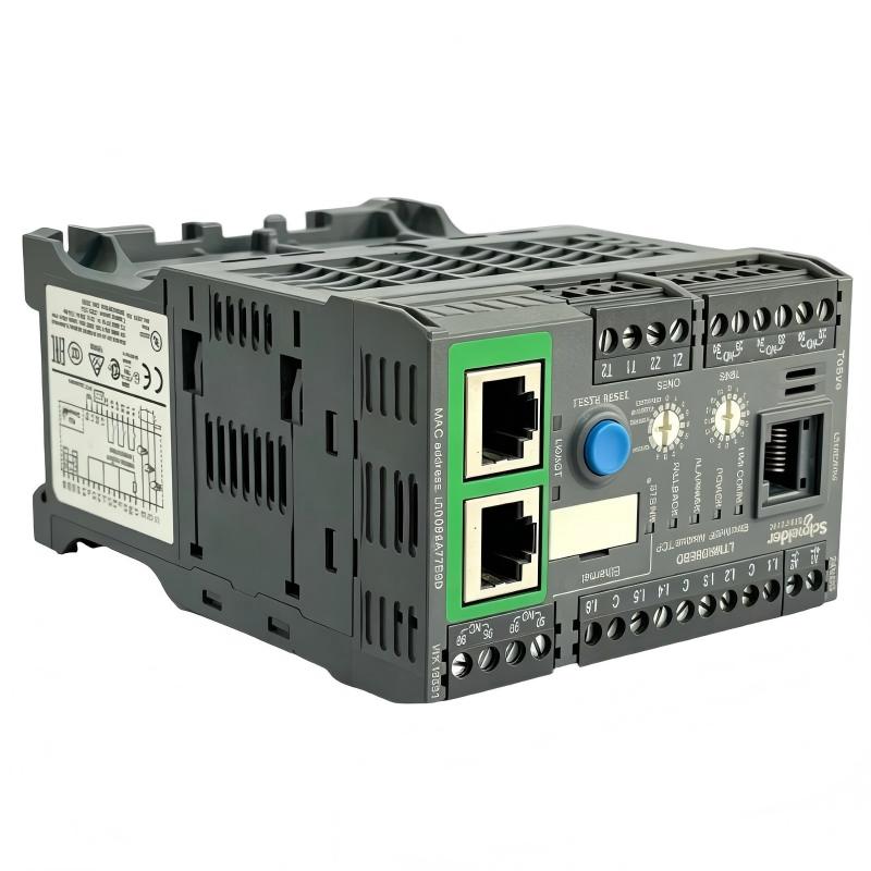
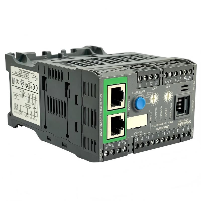
The Schneider Electric LTMR08EBD TeSys T Motor Controller is an intelligent motor management device designed for monitoring, protection, and control in industrial automation systems. It combines motor-current measurement, operating-condition monitoring, configurable protection functions, and Ethernet-based communication in a compact controller.
Part of Schneider Electric’s TeSys T motor management range, the LTMR08EBD is designed to help industrial operators monitor motor performance and identify abnormal operating conditions before they lead to unnecessary equipment downtime. It can be integrated into suitable PLC-based control architectures to provide motor status, alarms, diagnostic information, and control functions.
The controller supports a current measurement range of 0.4 to 8 A and operates from a 24 V DC control supply. Its Ethernet interface supports Modbus TCP and EtherNet/IP, allowing it to exchange information with compatible automation systems.
Unlike a conventional overload relay that primarily provides motor overload protection, the TeSys T system offers broader motor management capabilities. Depending on the configuration and connected components, it can monitor current, thermal conditions, phase imbalance, earth-fault conditions, and other operating parameters.
The LTMR08EBD is suitable for appropriately rated low-voltage motor applications where monitoring and communication are important. It is commonly considered for pumps, fans, conveyors, compressors, and other motor-driven equipment in manufacturing and process industries.
Because the model has a defined current range and a specific communication interface, engineers should verify motor ratings, protection requirements, and PLC compatibility before installation. The controller should be used with the required switching and short-circuit protection equipment as part of a properly engineered motor management system.
Technical Specifications
| Parameter | Specification |
|---|---|
| Brand | Schneider Electric |
| Product Range | TeSys |
| Product Family | TeSys T |
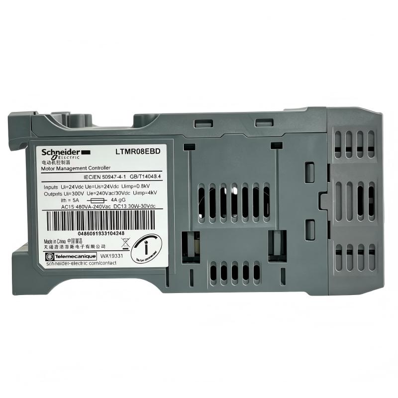
| Model | LTMR08EBD |
| Product Type | Motor Controller / Motor Management Controller |
| Current Measurement Range | 0.4–8 A |
| Rated Control Supply | 24 V DC |
| Supply Voltage Limits | 20.4–26.24 V DC |
| Typical Current Consumption | 56–127 mA |
| Communication Protocols | Modbus TCP, EtherNet/IP |
| Communication Interface | Ethernet, RJ45 |
| Ethernet Transmission Rate | 10–100 Mbit/s |
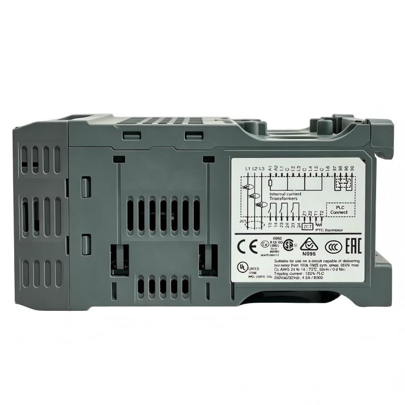
| Logic Inputs | 6 |
| Logic Outputs | 3 |
| Output Contact Configuration | 3 NO outputs; fault signaling includes 1 NO + 1 NC contact arrangement |
| Rated Insulation Voltage | 690 V |
| Short-Circuit Withstand Rating | Up to 100 kA under specified coordinated conditions |
| Measurement Functions | Current, temperature, earth-fault current, phase imbalance, and related motor data |
| Protection Functions | Overload, phase failure, locked rotor, thermal protection, and other configurable protections |
| Web Services | Integrated web server |
| Protection Rating | IP20 |
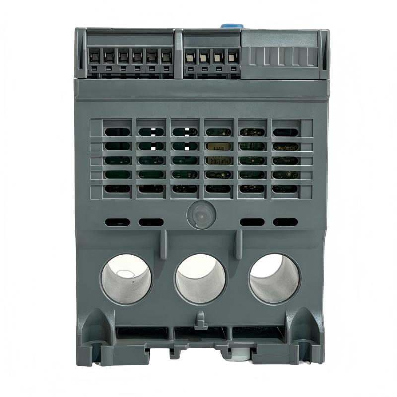
| Dimensions | 91 × 61 × 122.5 mm |
| Weight | 0.53 kg |
| Typical Application | Industrial motor monitoring, protection, and control |
Important: The controller’s short-circuit withstand rating depends on the specified protective devices and installation conditions. It does not mean the controller can independently interrupt a 100 kA fault.
Function and Working Principle
The LTMR08EBD monitors motor operating conditions and uses configured protection logic to identify conditions that may affect motor safety, reliability, or process continuity. It can also communicate operational data to a PLC, HMI, or supervisory control system through its Ethernet interface.
1. Motor Current Measurement
Current measurement is a central function of the TeSys T motor management system. The controller monitors motor-current information within its specified 0.4–8 A measurement range.
Motor current provides useful information about the operating state of connected equipment. Excessive current may indicate overload, mechanical obstruction, abnormal process demand, or a motor problem. Unexpectedly low current may also indicate an operating issue, depending on the application.
The measured values can be used by the controller’s protection functions and made available to the automation system for monitoring and diagnostics.
The connected motor and sensing arrangement must be compatible with the selected controller. Applications that exceed the supported current range require an appropriately rated alternative.
2. Thermal Overload Protection
Motor windings can overheat when a motor operates under excessive load, experiences repeated starts, or operates under unsuitable electrical conditions.
The LTMR08EBD supports thermal overload protection to help detect conditions that could damage the motor. Depending on the configured protection model, the controller evaluates operating information and determines when an overload condition requires an alarm or trip response.
Correct configuration is essential. Motor nameplate data, rated current, starting characteristics, and the expected operating duty should be considered during commissioning.
3. Phase Failure and Phase Imbalance Monitoring
Three-phase motors rely on an appropriate supply across all phases. Phase loss or significant phase imbalance can result in abnormal current, reduced torque, increased heating, and potential motor damage.
The controller supports phase-failure and phase-imbalance protection functions. When configured appropriately, these functions help identify abnormal supply conditions and support a defined response through the motor-control circuit.
Protection settings should reflect the motor, supply system, and operating requirements. They should not be adjusted solely to eliminate nuisance trips without investigating the underlying cause.
4. Locked-Rotor Detection
A locked rotor occurs when the motor is energized but cannot rotate as expected. This can result from a mechanical obstruction, a jammed driven component, or a motor fault.
A locked rotor can produce high current and rapid heating. The LTMR08EBD supports locked-rotor protection to help detect this type of abnormal condition.
The trip behavior depends on the configured protection parameters and system design. Mechanical interlocks and appropriate short-circuit protection remain necessary.
5. Earth-Fault Monitoring
Electrical insulation faults can create leakage current between energized conductors and earth. If not detected and addressed, these conditions may damage equipment and create safety risks.
The TeSys T motor management system supports earth-fault-related monitoring and protection. The available measurement arrangement and configuration determine how the controller detects and responds to these conditions.
The installation should follow the manufacturer’s requirements for the relevant sensing components, wiring, grounding, and protective-device coordination.
6. Diagnostic Data and Event Records
The LTMR08EBD supports diagnostic functions such as fault recording, trip history, operating-time information, starting-current records, and trip-context information.
These records can help maintenance personnel determine why a motor stopped and whether the event was associated with overload, phase conditions, or another monitored parameter.
Using diagnostic data can make troubleshooting more systematic than relying only on a general fault indication. The usefulness of the records depends on correct configuration and appropriate interpretation of the operating conditions.
Role in Industrial Control Systems
The LTMR08EBD can serve as the motor management layer between a motor-control circuit and the wider industrial automation system. It monitors motor conditions locally and exchanges relevant data with compatible control equipment.
PLC Integration
The controller supports Modbus TCP and EtherNet/IP over Ethernet. These protocols allow compatible PLCs and automation devices to exchange motor status, measurements, diagnostic information, and supported control commands.
In a typical installation, a PLC may use the controller’s information to coordinate motor operation with sensors, valves, conveyors, pumps, and other process equipment.
Before integration, engineers should verify the PLC’s supported protocol, network configuration, device addressing, and data mapping. Correct communication setup is necessary for dependable operation.
HMI and SCADA Monitoring
An HMI or supervisory control and data acquisition system can display motor current, operating status, alarms, and diagnostic records received through the automation network.
Operators can use this information to identify abnormal conditions, understand motor trips, and determine whether maintenance is required.
The exact data available on an HMI depends on the controller configuration, communication mapping, and software implementation.
Motor Starter and Contactor Coordination
The LTMR08EBD is a motor controller, not a standalone power contactor. It is used with the appropriate switching equipment and short-circuit protection to form a complete motor-control arrangement.
The controller’s outputs and control logic can participate in motor starting and stopping sequences, subject to the selected circuit design and ratings.
The contactor, overload protection, short-circuit protective device, and controller must be coordinated according to the manufacturer’s instructions and applicable electrical standards.
Alarm Management and Maintenance Planning
The controller’s diagnostic information can be incorporated into alarm management and maintenance workflows. Repeated overload events, phase faults, or abnormal starting conditions may indicate that the driven equipment needs inspection.
For example, recurring overload alarms on a pump may warrant checking the mechanical load, process conditions, motor bearings, and electrical supply before changing the protection settings.
Industrial Applications
The LTMR08EBD is intended for motor management applications where electrical protection, condition monitoring, and network communication are required.
1. Pumping Systems
Industrial pumps operate in water treatment, chemical processing, building services, and manufacturing systems. The LTMR08EBD can monitor compatible pump motors and help identify overload, phase failure, and other abnormal operating conditions.
When connected to a PLC or SCADA system, the controller’s information can help maintenance personnel investigate unexpected trips and recurring motor faults.
Pump-specific requirements, including starting current and operating duty, must remain within the system’s design limits.
2. Industrial Fans and Ventilation Equipment
Fans and ventilation systems often run for extended periods. Motor overload, phase imbalance, and thermal problems can affect availability and maintenance costs.
The LTMR08EBD can provide monitoring and protection for appropriately rated fan motors. Its network communication capabilities allow relevant motor information to be incorporated into a building or industrial control system.
The motor’s rated current must fall within the controller’s supported range, and the complete protection arrangement must be selected for the application.
3. Conveyor Systems
Conveyors are widely used in manufacturing, packaging, logistics, and material handling. A conveyor motor may experience increased load when material accumulates, a belt becomes obstructed, or mechanical components begin to deteriorate.
Motor monitoring can help identify abnormal current conditions and provide diagnostic information when a trip occurs. When integrated with PLC logic, the controller can form part of a coordinated shutdown or alarm strategy.
The safety functions of the complete machine must be designed separately according to the applicable risk assessment and standards.
4. Compressors and Auxiliary Machinery
Compressors and auxiliary motors may experience changing loads as process conditions vary. The controller can monitor suitable motors and provide protection and diagnostic information to the control system.
The exact suitability depends on the motor’s current, starting behavior, operating cycle, and protection requirements.
For critical compressor applications, the controller should be integrated with the manufacturer’s recommended motor protection and process safeguards.
5. Manufacturing and Process Equipment
Production lines frequently contain many motors serving mixers, feeders, transfer mechanisms, small pumps, and other equipment. A networked motor management controller can help centralize status monitoring and fault diagnosis.
The LTMR08EBD is most appropriate when the motor falls within its 0.4–8 A range and the installation requires its supported Ethernet protocols.
For larger motors or applications requiring different communication interfaces, a different controller variant may be necessary.
Installation and System Integration
Proper installation is essential for accurate motor measurement, reliable protection, and stable communication.
1. Verify Motor Compatibility
Before selecting the LTMR08EBD, check the motor nameplate current and ensure that the application falls within the controller’s 0.4–8 A measurement range.
Review the motor voltage, starting characteristics, duty cycle, and required protection functions. If the current requirements fall outside the supported range, select an appropriately rated motor management controller.
2. Provide the Correct Control Supply
The controller uses a 24 V DC supply, with documented operating limits of 20.4–26.24 V DC.
The control power supply should provide adequate capacity for the controller and any connected circuits supplied from it. Observe the required polarity and wiring arrangements.
Verify that the control supply remains within the permitted range during startup and normal operation.
3. Install Suitable Switching and Protection Equipment
The LTMR08EBD should be used as part of a complete motor starter or motor management assembly. The installation generally requires suitable switching equipment, such as a contactor, and coordinated short-circuit protection.
Select these components according to motor ratings, prospective fault current, operating duty, and the manufacturer’s coordination tables.
Do not treat the controller as a replacement for all protective devices in the motor circuit.
4. Configure Ethernet Communication
Connect the controller to the intended Ethernet network using the appropriate cabling and connection practices.
Configure the required network settings and confirm that the PLC or supervisory system supports Modbus TCP or EtherNet/IP as used by the application.
Test communication in both directions where required. Verify that motor status, measurements, alarms, and supported commands are mapped correctly in the automation software.
5. Configure Motor Protection Parameters
Set the motor’s rated current and other required protection parameters according to the nameplate and the manufacturer’s instructions.
Review overload, phase-failure, locked-rotor, earth-fault, and other applicable settings. The purpose is to provide appropriate protection while avoiding unnecessary trips caused by incorrect configuration.
Record the final settings and document any application-specific changes.
6. Test the Complete Motor Circuit
Before returning the system to production, check control wiring, contactor operation, interlocks, protective-device coordination, and network communication.
Perform controlled tests of start and stop commands, fault reporting, alarm behavior, and the expected response to relevant abnormal conditions.
Testing should be performed by qualified personnel following the plant’s electrical safety procedures.
Compatible System Components
The LTMR08EBD operates as part of a coordinated motor-control and automation system. The following components may be used depending on the application.
| Component | Function | Integration Considerations |
|---|---|---|
| Three-phase AC motor | Provides mechanical motion | Verify rated current, voltage, starting characteristics, and duty |
| Motor contactor | Switches motor power | Select according to the motor rating and required switching duty |
| Short-circuit protective device | Protects the power circuit against short circuits | Coordinate according to the manufacturer’s instructions |
| 24 V DC power supply | Supplies controller control power | Maintain the specified voltage range and adequate capacity |
| PLC | Coordinates motor operation and process logic | Verify Modbus TCP or EtherNet/IP compatibility |
| HMI | Displays motor measurements, status, and alarms | Configure appropriate data mapping |
| SCADA system | Provides supervisory monitoring and event handling | Confirm network architecture and supported data points |
| Ethernet switch | Connects compatible network devices | Follow network design, addressing, and cybersecurity practices |
| Motor sensors or earth-fault sensing components | Provide application-specific measurement inputs | Confirm the required sensing arrangement and controller compatibility |
The controller is not necessarily supplied with these additional components. Check the required bill of materials for the complete motor starter assembly.
Alternative Models and Replacement Considerations
When selecting an alternative to the LTMR08EBD, the current measurement range, communication protocol, control supply, input/output arrangement, and protection functions must all be considered.
| Alternative Model or Family | Key Considerations |
|---|---|
| Schneider Electric LTMR08MBD | TeSys T variant with Modbus communication; verify the network and feature requirements before substitution |
| Schneider Electric LTMR08EFM | TeSys T Ethernet variant with a 100–240 V AC control supply; not a direct electrical substitute for the 24 V DC model |
| Schneider Electric LTMR27EBD | Higher current-range Ethernet variant for suitable applications; verify the exact current range and system requirements |
| Schneider Electric TeSys Tera LTMTEBD system | Newer motor management platform that may require a compatible sensor module and system-level engineering |
| Other Schneider Electric motor management controllers | Select according to current range, supply voltage, communications, protection, and installation requirements |
A replacement should not be chosen solely because it belongs to the same product family. Before ordering, compare the following:
- Motor current range and measurement requirements.
- Control supply voltage.
- Communication protocols and network architecture.
- Number and type of logic inputs and outputs.
- Motor protection functions and configurable settings.
- Contactor and short-circuit protection coordination.
- Panel mounting and wiring arrangements.
- PLC program, data mapping, and commissioning requirements.
For an existing installation, replacing the LTMR08EBD with a newer controller may require changes to wiring, configuration, network addressing, and PLC software. A full compatibility review should be completed before removing the original unit.
Key Advantages
Comprehensive Motor Monitoring
The controller provides motor-current measurement and supports monitoring of relevant electrical and thermal operating conditions. This helps maintenance personnel assess motor status and investigate abnormal operation.
Multiple Protection Functions
Supported protection functions include overload, phase failure, locked-rotor, thermal overload, and earth-fault-related protection. The exact response depends on the selected configuration and connected equipment.
Ethernet-Based Communication
Modbus TCP and EtherNet/IP support integration with compatible PLCs, HMIs, and industrial supervisory systems.
Diagnostic and Event Information
Fault records, trip history, operating-time data, and related diagnostic information can help reduce troubleshooting time and support maintenance planning.
Compact Installation
The supplied dimensions of 91 × 61 × 122.5 mm and weight of 0.53 kg make the controller suitable for compact industrial control-panel layouts, subject to the required mounting and wiring clearances.
Support for Connected Motor Management
The LTMR08EBD allows motor information to be integrated into a broader automation strategy, helping operators coordinate equipment monitoring, alarms, and maintenance activities.
Technical FAQs
1. What is the Schneider Electric LTMR08EBD?
It is a TeSys T motor management controller designed for motor monitoring, protection, and control. It supports a 0.4–8 A current measurement range and uses a 24 V DC control supply.
2. Which communication protocols does the LTMR08EBD support?
It supports Modbus TCP and EtherNet/IP through its Ethernet interface. The network configuration must be set up for the intended PLC or supervisory system.
3. What is the current range of the LTMR08EBD?
Its documented current measurement range is 0.4–8 A. The motor and associated sensing arrangement must be suitable for this range.
4. Does the controller directly switch motor power?
The LTMR08EBD is a motor management controller rather than a standalone power contactor. It is used with suitable motor switching and short-circuit protection equipment in a complete motor-control arrangement.
5. What protection functions are available?
Supported functions include motor overload, phase failure, locked-rotor, thermal overload, and earth-fault-related protection, along with additional monitoring and diagnostic capabilities. The functions available in a particular installation depend on configuration and system design.
6. Can the LTMR08EBD communicate with a PLC?
Yes. Compatible PLCs can exchange data using Modbus TCP or EtherNet/IP. The PLC program must be configured to interpret the controller’s data and handle alarms and control commands appropriately.
7. What is the control supply voltage?
The controller uses 24 V DC, with specified supply limits of 20.4–26.24 V DC.
8. What are the dimensions and weight?
The specified dimensions are 91 × 61 × 122.5 mm, and the product weight is 0.53 kg.
9. Is the LTMR08EBD being discontinued?
Schneider Electric lists September 30, 2026, as the planned end of commercialization and January 31, 2027, as the end of standard service. Confirm actual availability and service support for the intended market before purchasing.
10. What should be checked before replacing an LTMR08EBD?
Confirm the motor current range, control supply, communications, input/output requirements, protection functions, mounting arrangement, and compatibility with the existing contactor and protective devices. Review PLC configuration and network settings before commissioning a replacement.
Procurement and Maintenance Recommendations
When purchasing the Schneider Electric LTMR08EBD, verify the full model number and confirm that the current range and 24 V DC supply match the application. Check that the intended PLC or automation system supports the required Ethernet protocol and that the controller’s input/output arrangement meets the control requirements.
For used or surplus equipment, inspect the terminal condition, housing, connectors, and identification label. Request available functional test information and confirm the supplier’s warranty and return terms. The controller’s compact dimensions and weight are useful for inventory and shipping records, but the supplied unit should still be checked against the actual product label.
During maintenance, inspect the control wiring, supply voltage, network connections, and associated motor switching equipment. Review event records and trip history to identify repeated overloads, phase faults, or other recurring problems.
Protection settings should be based on the motor nameplate and application requirements. Avoid increasing protection thresholds simply to prevent repeated trips without investigating the underlying cause.
Because the planned end of commercialization is September 30, 2026, buyers should confirm stock and after-sales support before planning a new installation or a long-term spare-parts strategy. Where appropriate, evaluate Schneider Electric’s recommended successor system and determine whether changes to sensing hardware, wiring, or PLC configuration will be required.
Conclusion
The Schneider Electric LTMR08EBD TeSys T Motor Controller is an intelligent motor management device designed for industrial motor monitoring, protection, and control. Its 0.4–8 A current measurement range, 24 V DC control supply, Ethernet communication through Modbus TCP and EtherNet/IP, and diagnostic capabilities make it suitable for compatible low-voltage motor applications.
For reliable operation, the controller must be configured for the connected motor and integrated with appropriate switching and short-circuit protection equipment. Engineers should also verify network compatibility, protection settings, and system-level behavior during commissioning.
As the model approaches its announced end of commercialization, accurate product identification and advance replacement planning can help maintain equipment availability and reduce disruption to industrial operations.