
NewsNEWCENTER
Featured products
Contact Us
Allen-Bradley 1738-OB8EM12 ArmorPoint Digital Output Module: Installation, Wiring, Configuration, and Commissioning Guide
2026-10-23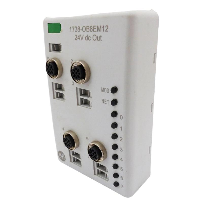
The Allen-Bradley 1738-OB8EM12 ArmorPoint Digital Output Module is an industrial distributed I/O device designed to control field actuators and other discrete-output loads in 24V DC automation systems. With eight sourcing digital outputs and M12 field connections, this module supports machine control, process equipment, material handling, and other industrial applications that require dependable digital output signals.
This installation guide explains how to prepare the mounting location, install the module, connect field devices, configure the controller, and commission the output channels. It also covers essential safety precautions and practical checks to help maintenance engineers and system integrators establish reliable operation.
Table of Contents
- Product Overview
- Technical Specifications
- Pre-Installation Preparation
- Module Mounting Procedure
- Field Wiring and Electrical Connections
- Controller Configuration
- Commissioning and Functional Testing
- Maintenance and Reliability
- Frequently Asked Questions
- Technical Summary
1. Product Overview
The 1738-OB8EM12 belongs to the Allen-Bradley ArmorPoint distributed I/O family. It provides eight digital output points that allow a controller to command compatible field devices through a distributed I/O architecture. Rather than routing every field signal directly to a central control cabinet, ArmorPoint modules can be installed closer to the equipment they control, helping simplify field wiring and machine layout.
The module uses 24V DC sourcing outputs. In a sourcing arrangement, an activated output supplies positive voltage to a compatible load, while the load’s return connects to the appropriate DC common. The actual wiring must follow the module’s terminal and connector diagrams, the field device requirements, and the electrical design of the machine.
The model includes M12-style field connections and a sealed housing intended for industrial environments. Environmental protection depends on correct installation, suitable mating connectors, intact seals, and properly fitted protective caps on unused ports.
Typical applications
- Operating compatible solenoid valves and pneumatic control devices.
- Switching indicator lamps and machine status signals.
- Controlling suitable interposing relays and contactor interface circuits.
- Commanding discrete actuators on automated production lines.
- Integrating field-level outputs with PLC-based distributed control systems.
2. Technical Specifications
| Parameter | Specification |
|---|---|
| Manufacturer | Allen-Bradley / Rockwell Automation |
| Model | 1738-OB8EM12 |
| Product family | ArmorPoint I/O |
| Module type | Digital output module |
| Number of outputs | 8 |
| Output type | 24V DC sourcing |
| Nominal field supply | 24V DC |
| Maximum output current | 1.0 A per channel, subject to the module’s rated conditions |
| Maximum total output current | 2.0 A per module, subject to the manufacturer’s loading and derating requirements |
| Field connection style | M12 DC Micro connectors |
| Published operating temperature range | -20°C to +60°C |
| Environmental protection | Designed for sealed industrial installation; confirm the applicable rating and connector requirements for the installed version |
Important: These headline values do not replace the full electrical specifications. Before connecting loads, confirm the exact module series, connector pin assignments, external supply capacity, output protection characteristics, and applicable derating requirements using the documentation for the installed unit.
3. Pre-Installation Preparation
3.1 Verify the module and system design
Check that the label identifies the correct 1738-OB8EM12 model. Inspect the module body, mounting interface, connectors, seals, and locking mechanism for damage. Confirm that the planned ArmorPoint base, adapter, power distribution arrangement, and controller configuration are suitable for the installed system.
Do not assume that another ArmorPoint output module is a direct substitute. Modules with similar model numbers may have different output types, connector layouts, current limits, or wiring requirements.
3.2 Prepare tools and materials
- Approved electrical test equipment rated for the installation.
- Compatible ArmorPoint mounting base and mounting hardware.
- Suitable M12 mating cables and field connectors.
- A correctly rated 24V DC supply and appropriately designed overcurrent protection.
- Controller configuration software and the correct module profile or electronic data sheet, where required.
- Product-specific installation instructions and connector pinout documentation.
3.3 Apply electrical safety procedures
Before installation or wiring, isolate the relevant electrical supplies and follow the site’s lockout/tagout procedure. Verify the absence of hazardous voltage using an approved instrument. Consider separate field power, stored energy, and energy supplied by connected actuators. Do not disconnect field wiring or modify connections while energized unless the equipment documentation explicitly permits the operation and the site’s approved procedures allow it.
4. Module Mounting Procedure
Step 1: Inspect the mounting location
Choose a location that meets the environmental and mechanical requirements of the installation. Avoid excessive vibration, direct mechanical impact, standing liquid, and exposure to chemicals beyond the enclosure’s capabilities. Make sure the connectors can be reached for maintenance without placing strain on the cables.
Step 2: Check the mounting base
Verify that the compatible mounting base is securely installed and correctly aligned. Inspect the base contacts and locking features for contamination, corrosion, or mechanical damage. Follow the manufacturer’s instructions for setting the base keying position for the intended module type.
Step 3: Seat the module
- Keep the system de-energized according to the applicable installation procedure.
- Position the module vertically above the mounting base.
- Align the module with the base and ensure that the module bridges the intended mounting interfaces as described in the installation instructions.
- Press the module into place until the locking mechanism engages.
- Check that the module is seated evenly and cannot move unexpectedly.
Do not force the module into the base. If the module does not seat correctly, remove it according to the prescribed procedure and check alignment, keying, and the condition of the locking features.
Step 4: Inspect the completed installation
Confirm that the module is securely retained, the connectors remain accessible, and the wiring route will not interfere with moving machinery. If the installation relies on the module’s environmental sealing, ensure that the mating connectors and any unused-port caps are compatible and properly fitted.
5. Field Wiring and Electrical Connections
5.1 Confirm the power arrangement
The 1738-OB8EM12 is designed for a nominal 24V DC field supply. Check the system’s power-distribution design before connecting it. Verify polarity, supply voltage, grounding and bonding arrangements, and protective-device ratings. The module’s control electronics and field-side load power may be handled differently within the overall ArmorPoint architecture; follow the applicable wiring diagrams rather than assuming that a single supply connection powers every circuit.
5.2 Connect the field loads
Each output is intended to switch a compatible DC load. In a typical sourcing circuit, the output provides positive voltage when commanded on, and current returns through the load’s designated DC common. The following simplified illustration explains the principle only; it is not a model-specific M12 pinout.
Controller output command
          |
          v
1738-OB8EM12 output channel
          |
          v
Compatible 24V DC field load
          |
          v
Approved DC return/common
Use the exact connector pinout in the product installation instructions to identify each output and its associated supply or common connection. Never infer pin assignments from connector appearance alone.
5.3 Check load compatibility
- Confirm that the load’s operating voltage matches the field supply.
- Verify that steady-state current and startup or inrush current remain within the channel and module limits.
- Account for the combined current of simultaneously activated outputs.
- Use suitable suppression for inductive loads, such as solenoids or relay coils, where required by the device and control design.
- Use an appropriately rated interposing relay or interface when a load exceeds the output’s electrical rating or requires a different switching arrangement.
- Separate field wiring from noise-sensitive analog or communication wiring where practical.
5.4 Secure the connectors
Inspect M12 connectors for bent contacts, dirt, moisture, damaged threads, or worn seals. Align each connector carefully and secure it according to the connector manufacturer’s instructions. Do not overtighten connectors or pull cables tightly against the module. Proper strain relief helps prevent intermittent connections caused by vibration and movement.
5.5 Verify wiring before energizing
- Compare each cable with the approved electrical drawings and I/O list.
- Check for accidental shorts between supply, output, and common conductors.
- Confirm that all loads are connected to the intended channels.
- Verify polarity and protective-device sizing.
- Ensure unused connectors are protected as required by the installation environment.
6. Controller Configuration
6.1 Confirm the network adapter
The 1738-OB8EM12 is a field I/O module, not a standalone PLC or network adapter. It must be used within a compatible ArmorPoint system and communicated with through the appropriate adapter and controller architecture. Confirm that the adapter, controller, network, and module arrangement are supported by the applicable system documentation.
6.2 Add the module to the project
- Open the controller project using the appropriate engineering software.
- Confirm that the relevant ArmorPoint adapter is correctly configured and communicating.
- Add or verify the 1738-OB8EM12 in the I/O configuration using the appropriate module profile, when required.
- Review the module’s input/output data mapping and status information.
- Verify the controller’s output tags and their association with the intended physical channels.
- Download the approved configuration following the site’s change-control procedure.
Exact software menus, profile versions, and configuration fields depend on the controller platform, adapter, firmware, and project version. Use the configuration documentation applicable to the installed system.
6.3 Create a clear I/O map
Maintain an I/O schedule that connects each controller tag to its field device and physical output channel. Use consistent names that reflect the equipment function, such as valve command, conveyor indicator, or actuator enable. Clear naming reduces commissioning errors and simplifies future troubleshooting.
| Configuration item | Verification |
|---|---|
| Module identity | Project entry matches the installed catalog number and supported series. |
| Output mapping | Each logical tag corresponds to the intended physical channel. |
| Field supply | Voltage and protective devices meet design requirements. |
| Network communication | Adapter and controller report normal communication status. |
| Startup behavior | Output states during startup, fault, and controller mode changes are understood and tested. |
7. Commissioning and Functional Testing
Step 1: Perform a pre-power inspection
Check mechanical seating, connector security, cable routing, supply polarity, and protective devices. Confirm that actuators can be tested safely and that unexpected movement will not endanger personnel or equipment.
Step 2: Energize the system in a controlled manner
Restore power according to the approved startup procedure. Observe the module and system status indicators. Check the controller and adapter diagnostics before attempting to command the outputs. Resolve any module-identification, network, or power faults before proceeding.
Step 3: Test one channel at a time
- Place the machine in an approved commissioning or maintenance state.
- Confirm that the field device and surrounding equipment are safe for testing.
- Command one output channel through the approved controller test method.
- Verify the expected output indication and field-device response.
- Return the channel to its safe state and record the result.
- Repeat for the remaining channels.
Do not force outputs on in an operating process merely to test them. Use approved maintenance modes and interlocks, and coordinate with the responsible control engineer.
Step 4: Verify normal and fault behavior
Check that outputs behave as intended during controller startup, communication loss, and applicable fault conditions. Verify that the machine’s safety design does not depend solely on a standard digital output module to perform a safety-rated function. Safety-related stopping and protective functions must use appropriately designed and rated equipment.
Step 5: Document the results
Record the installed module identity, channel assignments, test results, observed diagnostics, supply measurements, and any deviations from the drawings. Update the electrical documentation and controller project through the site’s approved revision process.
8. Maintenance and Reliability
Although the ArmorPoint module is designed for industrial use, periodic inspection helps reduce failures caused by vibration, moisture ingress, connector wear, and electrical overload.
- Inspect connectors, cable jackets, and seals during scheduled maintenance.
- Look for discoloration, unusual heat, corrosion, or physical damage.
- Review controller diagnostics and module status indicators when intermittent faults occur.
- Check that load current remains within the documented limits after equipment modifications.
- Keep an accurate record of module identity, wiring, configuration, and replacement history.
- Use a verified replacement with matching electrical and mechanical characteristics.
Rockwell Automation has listed the 1738-OB8EM12 as discontinued effective December 31, 2025, with no planned direct replacement category stated on its product listing. For maintenance planning, confirm availability and compatibility before purchasing a used or surplus unit. Do not assume that a different ArmorPoint model is interchangeable without an engineering review.
9. Frequently Asked Questions
What is the Allen-Bradley 1738-OB8EM12 used for?
It is an eight-channel 24V DC sourcing digital output module used to command compatible discrete field devices in an ArmorPoint distributed I/O system.
How many output channels does the module provide?
The module provides eight digital output points. Confirm the controller’s channel mapping and the field connector layout using the applicable product documentation.
Can each output drive a 24V DC load directly?
It can drive compatible loads when the voltage, current, load type, and protection requirements remain within the documented ratings. Loads that exceed the module’s limits or require different switching characteristics need an appropriate interface.
Can I install the module while the system is energized?
Do not assume that energized installation is permitted. Follow the exact product documentation and site procedures. The default safe approach is to isolate the relevant power sources before installation or wiring work.
Why should the connector pinout be checked before wiring?
M12 connectors can look similar while serving different electrical functions. The correct pinout prevents polarity errors, short circuits, incorrect load connections, and equipment damage.
What should be checked if an output does not operate during commissioning?
Check the controller command, I/O mapping, adapter communication, field supply, connector condition, load compatibility, module indicators, and any recorded diagnostic information. Isolate power before changing wiring.
10. Technical Summary
The Allen-Bradley 1738-OB8EM12 ArmorPoint Digital Output Module provides eight 24V DC sourcing outputs for distributed industrial control applications. Successful installation depends on correct base mounting, verified M12 wiring, adequate field power, compatible load selection, accurate controller mapping, and controlled functional testing.
For long-term reliability, follow the documentation for the exact installed series, observe per-channel and total-current limits, protect connectors against environmental exposure, and maintain clear wiring and configuration records. Because this model is discontinued, any replacement decision should include a careful review of electrical ratings, mechanical fit, connector assignments, controller support, and system compatibility.