

ProductPRODUCT
Featured products
Contact Us
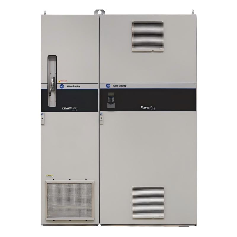
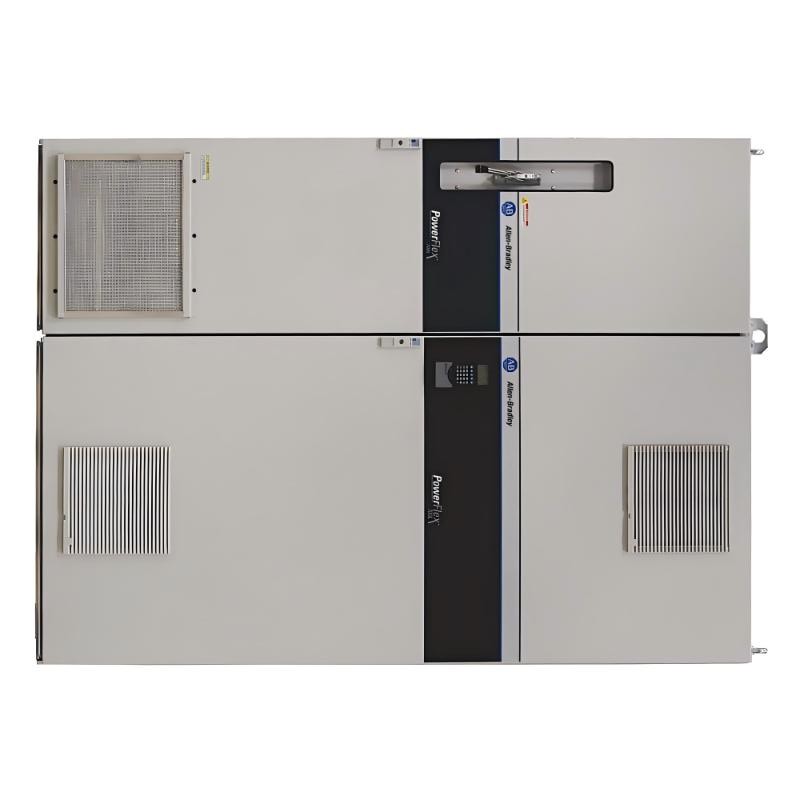
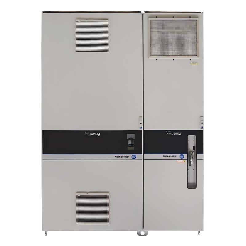
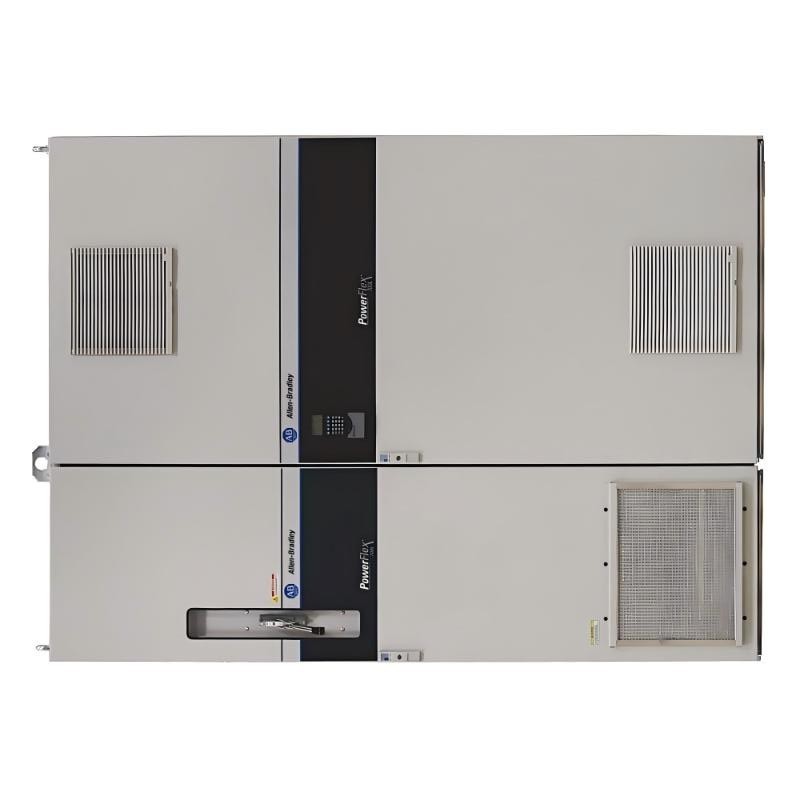
- Allen Bradley
- 20LC1K2A0ENNAN10WA
- PowerFlex 700L AC Drive
- USA
- 825.0 × 435.8 × 275.5 mm
- 71.44 kg
- Xiamen, China
- New & In Stock
- T/T, PayPal, Western Union
- 1 Year
- 1-3 Working Days
- DHL, UPS, TNT, FedEx and EMS.
- 24-Hour Service
- COO
- 5
Our advantage

Global Logistics
We have a 10-year logistics and express cooperation agreement, so our products can be shipped to any place in the world.

Brand new and original
Our products are imported in bulk from the place of origin. Because of the cooperative relationship, our products are all original and 100% new.

24-hour service
We provide 7*24 hours service to our customers. We will be there whenever you need us.

Price advantage
All our products are priced very favorably because we have our own warehouse and supply.
| Company Information | |||
| [email protected] | |||
| Mobile | +8615980777398 | ||
| +8615980777398 | |||
| 15980777398 |
Product Overview
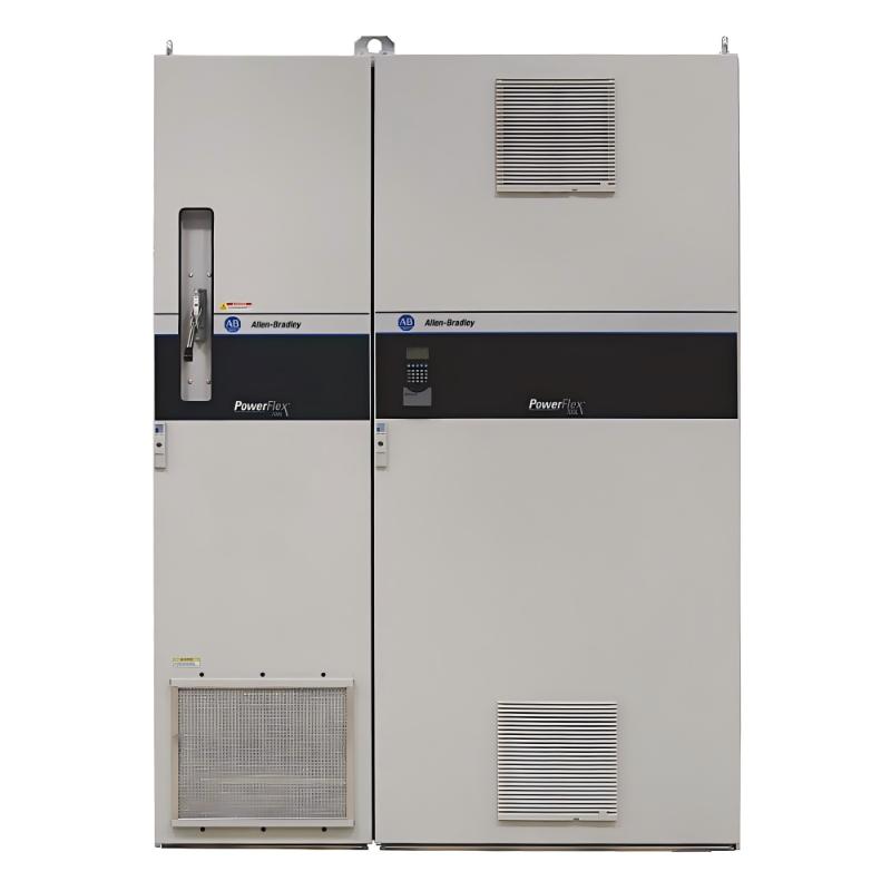
The Allen Bradley 20LC1K2A0ENNAN10WA is a PowerFlex 700L liquid-cooled AC drive rated at 1,250 A for 400 V three-phase industrial power systems. It belongs to the high-power end of the PowerFlex 700L family and is intended for large motor applications requiring regulated speed, controlled torque, and regenerative power conversion.
Unlike conventional drives that rely entirely on air cooling for their main power electronics, the PowerFlex 700L uses a liquid-cooled power structure. This arrangement supports high-power operation while transferring heat from the power section through a dedicated cooling circuit. The installation therefore needs to account for coolant circulation, heat removal, electrical protection, and the cabinet’s overall thermal design.
This catalog configuration uses PowerFlex 700 vector control with 24 V DC I/O. It is specified as a complete regenerative drive, allowing compatible systems to return energy to the AC supply during suitable operating conditions rather than dissipating all regenerated energy as heat. This can be particularly useful in applications involving frequent deceleration, overhauling loads, or repeated changes in motor speed.
The drive also supports encoder-based feedback when an appropriate external feedback arrangement is installed. Its control architecture can accommodate sensorless vector control, V/Hz control, and vector control with feedback, depending on the selected configuration and application requirements. The actual control method must be established through the drive’s supported settings and compatible system components.
In a large industrial compressor, material-handling installation, or process machine, motor speed and torque may need to change as the production load varies. The PowerFlex 700L can regulate the connected motor while the plant control system coordinates operating sequences, process signals, and protective interlocks.
The 20LC1K2A0ENNAN10WA configuration does not include a Human Interface Module, an internal brake IGBT, a drive-mounted brake resistor, or an internal communication module. Its control interface is based on PowerFlex 700 vector control with 24 V DC I/O. These distinctions matter when planning the complete installation, particularly where operator access, external communications, and regenerative energy handling must be incorporated into the system.
Technical Specifications
| Parameter | Specification |
|---|---|
| Manufacturer | Allen-Bradley |
| Model | 20LC1K2A0ENNAN10WA |
| Product Family | PowerFlex 700L |
| Product Type | Liquid-Cooled Regenerative AC Drive |
| Drive Series | 20L |
| Frame Size | Frame 3B |
| Rated Input Voltage | 400 V AC |
| Input Phases | Three-phase |
| Rated Output Current | 1,250 A |
| Normal-Duty Power Rating | 715 kW (960 HP) |
| Heavy-Duty Power Rating | 525 kW (700 HP) |
| Drive Architecture | Complete regenerative drive |
| Control Method | PowerFlex 700 vector control |
| Control I/O Supply | 24 V DC |
| Cooling Method | Liquid-cooled power structure |
| Analog Inputs | 2 |
| Analog Outputs | 2 |
| Digital Inputs | 6 |
| Digital Outputs | 3 |
| Internal Communication Module | Not included |
| Human Interface Module | Not included; blank plate |
| Internal Brake IGBT | Not included |
| Drive-Mounted Brake Resistor | Not included |
| Enclosure Rating | IP20 / NEMA/UL Type 1 |
| Dimensions | 825.0 × 435.8 × 275.5 mm |
| Weight | 71.44 kg |
Product Features
- 1,250 A rated output current: Supports high-power motor applications within the drive’s specified electrical and thermal limits.
- 715 kW normal-duty rating: Provides the stated power capacity for normal-duty operation at the specified supply voltage.
- 525 kW heavy-duty rating: Defines the corresponding power capacity for heavy-duty applications.
- Liquid-cooled power structure: Transfers heat from the power electronics through a dedicated cooling arrangement.
- Regenerative operation: Supports returning compatible regenerated energy to the AC supply during suitable operating conditions.
- PowerFlex 700 vector control: Provides motor regulation through the specified control architecture.
- 24 V DC control I/O: Supports integration with compatible external control circuits.
- Encoder-feedback capability: Supports applicable motor-control configurations using compatible external feedback equipment.
- Integrated analog and digital I/O: Provides two analog inputs, two analog outputs, six digital inputs, and three digital outputs.
- Open-type power installation: Uses the specified IP20/NEMA/UL Type 1 enclosure arrangement.
- Blank front plate: The supplied configuration does not include a Human Interface Module.
- External braking arrangement: Does not include an internal brake IGBT or drive-mounted brake resistor.
Working Principle
The 20LC1K2A0ENNAN10WA converts incoming three-phase AC power into a controlled electrical output for a connected motor. Its liquid-cooled power structure manages heat generated by the power electronics, while its regenerative architecture supports bidirectional energy flow between the motor system and the AC supply under appropriate operating conditions.
Three-Phase AC Supply → Regenerative Power Converter → DC Power Bus → Inverter Power Section → AC Motor → Mechanical Load
During motoring operation, the drive supplies controlled electrical power to the motor. The inverter regulates the output according to the selected motor-control method, allowing speed and torque to follow the configured operating requirements.
When the connected motor decelerates or an overhauling load drives the motor, energy can flow back toward the drive’s DC bus. The regenerative power-conversion system can transfer this energy back to the AC supply when the operating conditions and installation permit. This differs from a conventional braking arrangement that dissipates regenerated energy through a resistor.
The drive’s PowerFlex 700 vector control configuration supports motor regulation through its control electronics and available I/O. Depending on the selected control mode, the drive can operate using voltage and frequency relationships, sensorless vector control, or compatible feedback-based vector control. Encoder-based operation requires a suitable external feedback arrangement and the corresponding configuration.
The liquid-cooling circuit removes heat from the power section. Coolant flow, inlet temperature, heat-exchanger capacity, and the condition of the cooling connections all affect the thermal performance of the installation. An interruption in coolant circulation can lead to excessive temperatures even when the electrical load is otherwise within its rated range.
External control equipment can use the drive’s analog and digital I/O to coordinate motor operation. A PLC may issue run commands, provide reference signals, and process status information while managing the wider machine sequence. Because this configuration does not include an internal communication module, the required communication functions must be provided by a compatible external arrangement if network connectivity is needed.
Role in a PowerFlex 700L Motor Control Architecture
The 20LC1K2A0ENNAN10WA functions as the high-power motor-control and regenerative conversion stage in an industrial drive system. It regulates the connected motor while the cooling system, upstream protection, external controller, and plant electrical infrastructure support continuous operation.
Three-Phase AC Supply → Protective Devices → Regenerative Converter → DC Bus → Inverter Power Section → Motor → Driven Equipment
| System Component | Function |
|---|---|
| Allen-Bradley 20LC1K2A0ENNAN10WA | Controls motor operation and supports regenerative power conversion |
| Three-Phase AC Supply | Provides the drive’s input electrical power |
| Input Protective Devices | Provide the specified electrical protection for the installation |
| Regenerative Converter | Transfers power between the AC supply and the drive’s DC bus |
| DC Power Bus | Transfers electrical energy between the converter and inverter sections |
| Inverter Power Section | Supplies controlled electrical output to the motor |
| Liquid-Cooling Circuit | Removes heat from the power electronics |
| External Cooling Equipment | Circulates and removes heat from the coolant according to the installation design |
| PLC or Industrial Controller | Coordinates motor commands, operating sequences, and machine interlocks |
| Analog and Digital I/O | Carries supported control signals and status information |
| Compatible AC Motor | Converts electrical energy into mechanical output |
| Mechanical Transmission | Transfers motor torque to the driven equipment |
| Supervisory Interface | Supports operator monitoring and system-level control |
Industrial Applications
| Application | Typical Use |
|---|---|
| Large Industrial Compressors | Regulating compatible high-power motor operation under changing process loads |
| Heavy Material Handling | Controlling motor speed and managing regenerated energy during deceleration |
| Industrial Processing Lines | Coordinating large motor-driven equipment with production requirements |
| Metal Processing Equipment | Regulating compatible high-power drives in demanding operating cycles |
| Large Pumping Systems | Controlling motor operation in high-capacity process installations |
| Industrial Test Facilities | Regulating motor speed and torque during equipment testing |
| Continuous Manufacturing Plants | Maintaining controlled motor operation across changing production demands |
| High-Power Conveyor Systems | Managing acceleration, transport speed, and stopping sequences |
| Regenerative Drive Systems | Returning suitable regenerated energy to the AC supply |
| Centralized Motor-Control Installations | Integrating high-power motor regulation into a coordinated plant electrical system |
Installation and Maintenance
- Confirm the drive configuration: Verify that 20LC1K2A0ENNAN10WA matches the required 400 V power system, current rating, PowerFlex 700 vector control arrangement, and regenerative operating requirements.
- Check the incoming electrical supply: Confirm that the three-phase supply and upstream protective devices are suitable for the drive installation.
- Establish electrical isolation: Follow the applicable lockout/tagout procedure and verify that stored electrical energy has been discharged before servicing power connections or internal components.
- Review the motor requirements: Compare the motor nameplate data and operating duty with the drive’s 715 kW normal-duty and 525 kW heavy-duty ratings.
- Inspect the liquid-cooling system: Check coolant circulation, connections, heat-removal equipment, and operating conditions against the installation requirements.
- Verify electrical protection: Check that the selected protective devices and power connections comply with the drive’s electrical requirements and the installation design.
- Inspect the power bus connections: Check the AC input, DC bus connections, motor terminals, grounding, and associated conductors before energizing the equipment.
- Configure motor control: Enter the motor data and establish the intended control method, operating limits, reference sources, and acceleration and deceleration parameters.
- Check the feedback arrangement: Where encoder-based control is used, verify the external feedback hardware, wiring, signal compatibility, and configured parameters.
- Review regenerative operation: Confirm that the AC supply arrangement and installation design support the intended return of regenerated energy.
- Perform controlled commissioning: Verify motor direction, operating response, coolant circulation, control I/O, and regenerative behavior under approved operating conditions.
- Record maintenance results: Document the drive configuration, motor parameters, cooling-system checks, protection settings, and commissioning findings for future troubleshooting.
Related Components
| Component | Function |
|---|---|
| Allen-Bradley 20LC1K2A0ENNAN10WA | PowerFlex 700L liquid-cooled regenerative AC drive |
| Three-Phase AC Supply | Provides electrical power for the drive system |
| Compatible AC Motor | Converts controlled electrical power into mechanical output |
| Regenerative Converter Section | Transfers power between the AC supply and DC bus |
| DC Power Bus | Transfers electrical energy between the converter and inverter sections |
| Liquid-Cooling Equipment | Circulates coolant and removes heat from the power electronics |
| External Heat Exchanger | Transfers heat from the coolant to the installation’s heat-removal medium |
| PLC or Industrial Controller | Coordinates drive commands and machine operating sequences |
| Compatible Encoder and Feedback Equipment | Supplies feedback signals for supported closed-loop motor control |
| Branch-Circuit Protective Devices | Provide the required electrical protection |
| Analog and Digital Control Wiring | Carries supported operating commands and status signals |
| Operator Interface | Supports monitoring and operator interaction through a compatible arrangement |
Recommended Related Models
| Model / Product Family | Product Type | Typical Application |
|---|---|---|
| Allen-Bradley 20LC1K2A0ENNAN10WA | PowerFlex 700L Regenerative AC Drive, 1,250 A | High-power motor regulation with PowerFlex 700 vector control |
| Allen-Bradley 20LC650A0ENNAN10WA | PowerFlex 700L Regenerative AC Drive, 650 A | Lower-current applications within the PowerFlex 700L family |
| Allen-Bradley 20LC360N0ENNAN10WA | PowerFlex 700L Regenerative AC Drive, 360 A | Applications requiring a lower rated output current |
| Allen-Bradley PowerFlex 700L Series | Liquid-Cooled Regenerative AC Drive Family | High-power motor control with regenerative power conversion |
| Allen-Bradley PowerFlex 755T Series | Regenerative AC Drive Family | Evaluating alternative regenerative drive architectures for industrial applications |
Key Advantages
- Provides a 1,250 A rated output current for compatible high-power motor applications.
- Supports 715 kW normal-duty and 525 kW heavy-duty operation.
- Uses a liquid-cooled power structure for thermal management.
- Supports regenerative energy transfer to the AC supply under suitable operating conditions.
- Provides PowerFlex 700 vector control with 24 V DC I/O.
- Includes analog and digital I/O for external control integration.
Technical FAQs
What distinguishes the PowerFlex 700L from a conventional air-cooled AC drive?
The PowerFlex 700L uses a liquid-cooled power structure to remove heat from its main power electronics. It also supports regenerative power conversion, making it suitable for high-power installations where cooling design and energy flow are important parts of the system architecture.
How does regenerative operation affect a motor system during deceleration?
During deceleration, the motor can return energy to the drive’s DC bus. The regenerative converter can transfer suitable regenerated energy back to the AC supply, reducing the need to dissipate that energy through a braking resistor. The result depends on the operating conditions and the electrical system’s ability to accept the returned power.
What control functions are available with the 20LC1K2A0ENNAN10WA?
This configuration uses PowerFlex 700 vector control with 24 V DC I/O. It supports the specified analog and digital control signals, while encoder-based operation requires compatible external feedback equipment and the appropriate drive configuration.
What needs to be considered when integrating the drive into a liquid-cooled installation?
The cooling circuit must provide the required coolant circulation and heat-removal capacity under the intended operating conditions. Coolant temperature, flow, connections, and external heat-exchange equipment should be considered alongside the electrical ratings and motor load when commissioning the system.