

ProductPRODUCT
Featured products
Contact Us
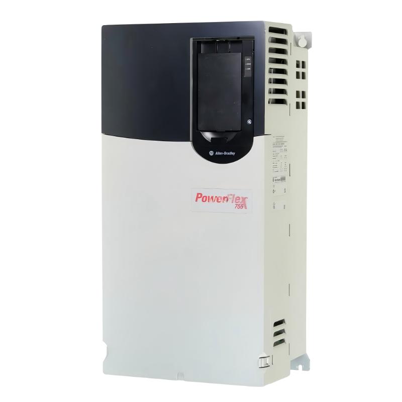
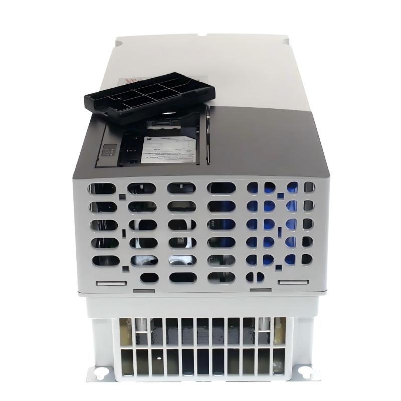
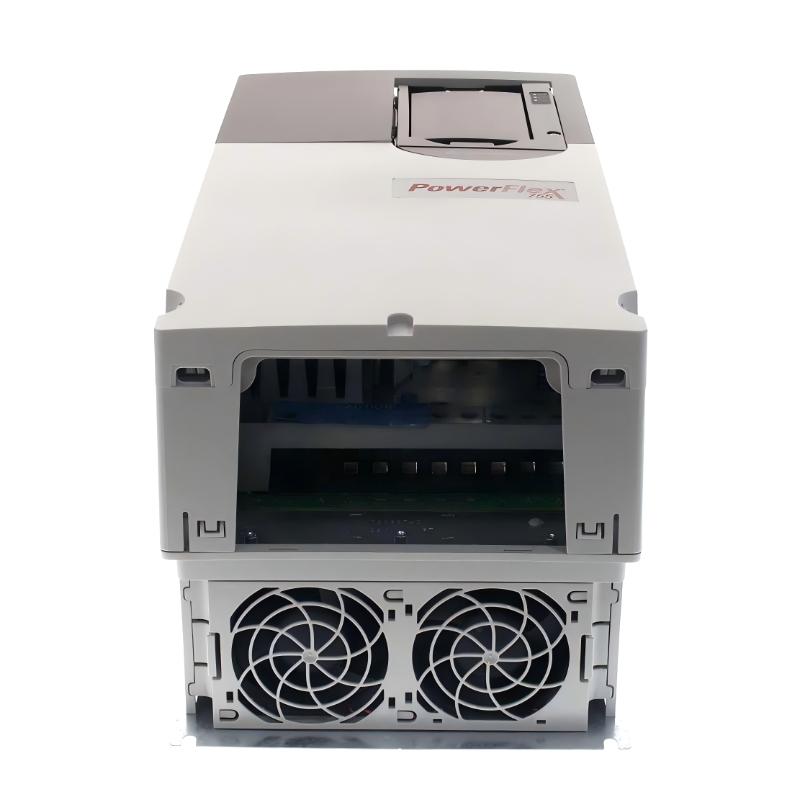
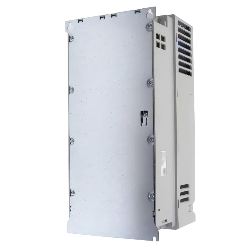
- Allen Bradley
- 20G11ND052AA0NNNNN
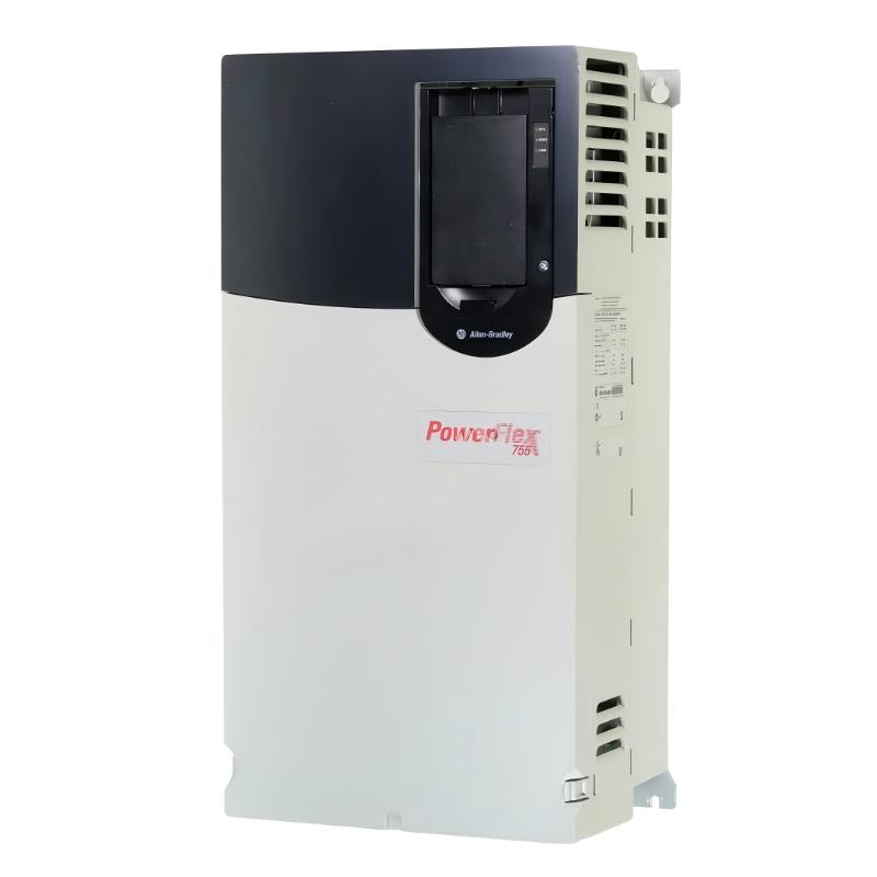
- PowerFlex 755 AC Drive
- USA
- 474 × 212 × 222 mm
- 13.6 kg
- Xiamen, China
- New & In Stock
- T/T, PayPal, Western Union
- 1 Year
- 1-3 Working Days
- DHL, UPS, TNT, FedEx and EMS.
- 24-Hour Service
- COO
- 5
Our advantage

Global Logistics
We have a 10-year logistics and express cooperation agreement, so our products can be shipped to any place in the world.

Brand new and original
Our products are imported in bulk from the place of origin. Because of the cooperative relationship, our products are all original and 100% new.

24-hour service
We provide 7*24 hours service to our customers. We will be there whenever you need us.

Price advantage
All our products are priced very favorably because we have our own warehouse and supply.
| Company Information | |||
| [email protected] | |||
| Mobile | +8615980777398 | ||
| +8615980777398 | |||
| 15980777398 |
Product Overview
The Allen Bradley 20G11ND052AA0NNNNN is a PowerFlex 755 adjustable-frequency AC drive rated at 52 A, with a normal-duty power rating of 30 kW and a heavy-duty rating of 22 kW. It operates on a 480 V three-phase AC supply and combines variable-speed motor control with embedded EtherNet/IP communication and an internal dynamic braking transistor.
The PowerFlex 755 series is intended for industrial applications where motor speed, acceleration, deceleration, and torque response must be coordinated with the operating requirements of a machine. Its adjustable-frequency output allows a connected motor to operate at different speeds instead of running continuously at the frequency of the incoming supply.
This model uses an AC input with precharge and DC terminals. Its open-type enclosure, integral EMC filter configuration, and internal braking transistor are relevant when incorporating the drive into an industrial control cabinet. The filtering configuration for this catalog number specifies that the common-mode jumper is removed, which distinguishes it from other PowerFlex 755 configurations with different filtering arrangements.
Embedded EtherNet/IP provides a communication path to compatible industrial controllers. In a Logix-based automation system, the controller can coordinate drive commands, speed references, status information, and machine interlocks. The drive manages motor operation, while the controller coordinates the wider production sequence.
The model is supplied without a Human Interface Module (HIM), using a blank front panel. Drive configuration and monitoring can be handled through compatible software and the installed automation architecture.
Dynamic braking is another useful feature. During deceleration, a motor can return energy to the drive’s DC bus. The internal braking transistor supports a compatible external braking resistor arrangement when the application requires additional braking capability. The resistor itself is not included in this drive configuration.
For example, a conveyor system may require controlled acceleration to reduce sudden mechanical loading, followed by a defined stopping sequence when material reaches the next production stage. The PowerFlex 755 can regulate the motor according to its configured parameters while the PLC coordinates sensors, interlocks, and adjacent equipment.
Technical Specifications
| Parameter | Specification |
|---|---|
| Manufacturer | Allen-Bradley |
| Model | 20G11ND052AA0NNNNN |
| Product Family | PowerFlex 755 |
| Product Type | Adjustable-Frequency AC Drive |
| Drive Series | 20G |
| Frame Size | Frame 4 |
| Rated Input Voltage | 480 V AC |
| Input Phases | Three-phase |
| Rated Output Current | 52 A |
| Normal-Duty Power Rating | 30 kW |
| Heavy-Duty Power Rating | 22 kW |
| Input Arrangement | AC input with precharge and DC terminals |
| Network Communication | Embedded EtherNet/IP |
| Enclosure Type | IP20/IP00, NEMA/UL Open Type |
| EMC Filtering | Integral EMC filter, common-mode jumper removed |
| Dynamic Braking | Internal dynamic braking transistor |
| Human Interface Module | Not included; blank front panel |
| Cooling Method | Air-cooled |
| Dimensions | 474 × 212 × 222 mm |
| Weight | 13.6 kg |
Product Features
- 52 A rated output current: Supports compatible motor applications within the drive’s electrical and thermal operating limits.
- 30 kW normal-duty rating: Defines the rated power capacity for normal-duty applications.
- 22 kW heavy-duty rating: Provides the corresponding power rating for more demanding load conditions.
- Embedded EtherNet/IP: Supports communication with compatible industrial controllers and automation networks.
- AC input with precharge: Uses the specified input arrangement to manage the drive’s power-up sequence.
- DC terminals: Provide the designated DC connections within the drive’s power architecture.
- Internal dynamic braking transistor: Supports a suitable external braking resistor arrangement when required.
- Integral EMC filter: Supports electromagnetic compatibility in the intended installation.
- Common-mode jumper removed: Defines the specified filtering configuration for this catalog number.
- Air-cooled construction: Uses airflow to manage heat generated during operation.
- Blank front panel: The supplied configuration does not include a Human Interface Module.
- Open-type enclosure: Supports installation within a suitable electrical cabinet or enclosure.
Working Principle
The 20G11ND052AA0NNNNN converts incoming three-phase AC power into a controlled electrical output for an AC motor. By adjusting output voltage and frequency according to the selected control mode, the drive regulates motor speed and supports controlled acceleration and deceleration.
Three-Phase AC Supply → PowerFlex 755 Drive → Controlled AC Output → Motor → Mechanical Load
The incoming AC supply passes through the drive’s input and precharge arrangement before the internal DC bus is established. The power-conversion section then generates a controlled output for the motor. This allows motor operation to follow the configured speed reference rather than remaining tied to the fixed frequency of the incoming supply.
The drive’s control system processes operating commands and applies the configured motor-control parameters. A PLC can provide run commands, speed references, and operating interlocks through the supported control interfaces. Embedded EtherNet/IP also allows the drive to exchange supported command and status data with compatible automation equipment.
When the motor decelerates, it may return energy to the DC bus. If the application requires dynamic braking, the internal braking transistor can switch a compatible external resistor into the braking circuit to dissipate the regenerated energy. The braking arrangement must be selected according to the expected energy, stopping frequency, and thermal requirements.
The DC terminals form part of the drive’s specified electrical architecture. Their use must follow the applicable power-system design and connection requirements rather than being treated as unrestricted terminals for an arbitrary external DC supply.
The drive’s operating response depends on the motor data, control mode, speed references, acceleration and deceleration settings, and mechanical load. Correct parameter configuration and controlled commissioning are therefore necessary to establish the intended operating behavior.
Role in a PowerFlex 755 Motor Control Architecture
The 20G11ND052AA0NNNNN occupies the motor-control position between the three-phase power supply and the connected motor. It regulates motor operation and communicates with compatible automation equipment, while external protection and control components support the complete machine installation.
Three-Phase AC Supply → PowerFlex 755 Drive → AC Motor → Mechanical Transmission → Driven Equipment
| System Component | Function |
|---|---|
| Allen-Bradley 20G11ND052AA0NNNNN | Regulates motor operation and supports network communication |
| Three-Phase AC Supply | Provides the drive’s input electrical power |
| Precharge Circuit | Supports the drive’s power-up sequence |
| Power-Conversion Section | Generates the controlled output supplied to the motor |
| Embedded EtherNet/IP Interface | Exchanges supported commands and status information |
| PLC or Industrial Controller | Coordinates motor commands and machine sequences |
| AC Motor | Converts electrical energy into mechanical output |
| Dynamic Braking Circuit | Dissipates braking energy through a suitable external resistor when required |
| Branch-Circuit Protection | Provides the required electrical protection |
| Motor Cable | Connects the drive output to the motor |
| Supervisory Interface | Supports configuration, monitoring, and operator interaction |
Industrial Applications
| Application | Typical Use |
|---|---|
| Industrial Conveyors | Regulating transport speed and controlling acceleration and stopping |
| Material Handling Systems | Coordinating motor operation with automated handling sequences |
| Packaging Machinery | Controlling compatible motor-driven mechanisms during production |
| Pumping Systems | Adjusting motor speed according to process-flow requirements |
| Industrial Ventilation | Regulating compatible fan motors under changing operating conditions |
| Manufacturing Equipment | Integrating motor-speed control with PLC-based sequences |
| Processing Machinery | Maintaining defined motor operating conditions during production |
| Automated Assembly Lines | Coordinating motor operation with sensors and adjacent equipment |
| Deceleration-Critical Machinery | Using a compatible braking arrangement where controlled stopping is required |
| Networked Motor Control Systems | Exchanging drive commands and status data over EtherNet/IP |
Installation and Maintenance
- Confirm the drive configuration: Verify that 20G11ND052AA0NNNNN matches the required voltage class, output current, input arrangement, and braking configuration.
- Check the incoming supply: Confirm that the three-phase AC source meets the drive’s electrical requirements.
- Establish electrical isolation: Follow the applicable lockout/tagout procedure and verify that stored electrical energy has been discharged before servicing the drive.
- Review motor requirements: Compare the motor nameplate data and operating duty with the drive’s 30 kW normal-duty and 22 kW heavy-duty ratings.
- Inspect the installation environment: Check cabinet ventilation, ambient conditions, enclosure protection, and mounting arrangements against the applicable installation requirements.
- Verify branch-circuit protection: Check that the selected protective devices are appropriate for the drive and the installed electrical system.
- Inspect power connections: Check the incoming supply terminals, motor connections, grounding, and cable condition before energizing the equipment.
- Configure EtherNet/IP communication: Set up the network connection and controller integration, including the command and status data used by the machine-control program.
- Configure motor parameters: Enter the required motor data and establish the control mode, speed references, acceleration, and deceleration settings.
- Review the braking arrangement: Determine whether an external braking resistor is required and ensure that its electrical and thermal ratings suit the expected stopping duty.
- Perform controlled commissioning: Verify motor direction, commanded speed, acceleration, deceleration, network communication, and operating response under controlled conditions.
- Record maintenance results: Document the drive configuration, motor parameters, network settings, braking arrangement, and commissioning findings for future troubleshooting.
Related Components
| Component | Function |
|---|---|
| Allen-Bradley 20G11ND052AA0NNNNN | PowerFlex 755 AC drive with embedded EtherNet/IP |
| Three-Phase AC Supply | Supplies electrical power to the drive |
| Compatible AC Motor | Converts controlled electrical output into mechanical power |
| PLC or Industrial Controller | Coordinates drive commands and machine sequences |
| EtherNet/IP Network Components | Provide communication between the drive and compatible automation equipment |
| External Braking Resistor, Where Required | Dissipates braking energy through the internal dynamic braking transistor |
| Branch-Circuit Protective Devices | Provide the required electrical protection |
| Motor Cable | Connects the drive output to the motor |
| Compatible Drive Configuration Software | Supports parameter setup and troubleshooting |
| Operator Interface | Supports monitoring and operator commands through the configured control system |
Recommended Related Models
| Model / Product Family | Product Type | Typical Application |
|---|---|---|
| Allen-Bradley 20G11ND052AA0NNNNN | PowerFlex 755 AC Drive, 52 A | 480 V three-phase motor control with embedded EtherNet/IP |
| Allen-Bradley 20G11ND052JA0NNNNN | PowerFlex 755 AC Drive, 52 A | Related configuration for applications requiring the corresponding replacement model |
| Allen-Bradley PowerFlex 755 Series | Adjustable-Frequency AC Drive Family | Industrial motor-speed regulation and networked control |
| Allen-Bradley PowerFlex 753 Series | Adjustable-Frequency AC Drive Family | Industrial motor-control applications with a different feature and option arrangement |
| Compatible EtherNet/IP Controllers | Industrial Automation Controllers | Coordinating drive operation with machine and process sequences |
Key Advantages
- Provides 52 A rated output current for compatible motor applications.
- Supports 30 kW normal-duty and 22 kW heavy-duty operation.
- Integrates embedded EtherNet/IP communication.
- Includes an internal dynamic braking transistor for compatible braking arrangements.
- Uses an AC input with precharge and designated DC terminals.
- Supports integration into networked industrial motor-control systems.
Technical FAQs
How does the AC input with precharge affect the drive’s power-up sequence?
The precharge arrangement supports the initial charging of the drive’s internal DC bus when power is applied. This is part of the drive’s power-conversion architecture and should be maintained according to the specified installation and connection requirements.
What is the significance of the common-mode jumper being removed?
The jumper position defines the specified filtering configuration for this catalog number. It affects the drive’s electrical configuration and should not be changed casually when replacing the drive or modifying the installation.
Does the internal dynamic braking transistor eliminate the need for an external braking resistor?
No. The transistor provides the switching function for a compatible braking circuit, but an external resistor is required when the application needs that braking arrangement. The resistor must be selected for the expected braking energy and operating cycle.
What should be checked if EtherNet/IP commands reach the drive but the motor does not run?
Check the drive’s operating state, active faults, configured command source, start permissives, interlocks, and motor-control parameters. Also verify that the commanded operating mode and reference source match the machine-control program.