

ProductPRODUCT
Featured products

Contact Us
- Schneider
- XCC-1510PS05X
- XCC Incremental Encoder
- France
- 58 mm
- 0.465 kg
- Xiamen, China
- New & In Stock
- T/T, PayPal, Western Union
- 1 Year
- 1-3 Working Days
- DHL, UPS, TNT, FedEx and EMS.
- 24-Hour Service
- COO
- 6
Our advantage

Global Logistics
We have a 10-year logistics and express cooperation agreement, so our products can be shipped to any place in the world.

Brand new and original
Our products are imported in bulk from the place of origin. Because of the cooperative relationship, our products are all original and 100% new.

24-hour service
We provide 7*24 hours service to our customers. We will be there whenever you need us.

Price advantage
All our products are priced very favorably because we have our own warehouse and supply.
| Company Information | |||
| [email protected] | |||
| Mobile | +8615980777398 | ||
| +8615980777398 | |||
| 15980777398 |
1. Product Overview
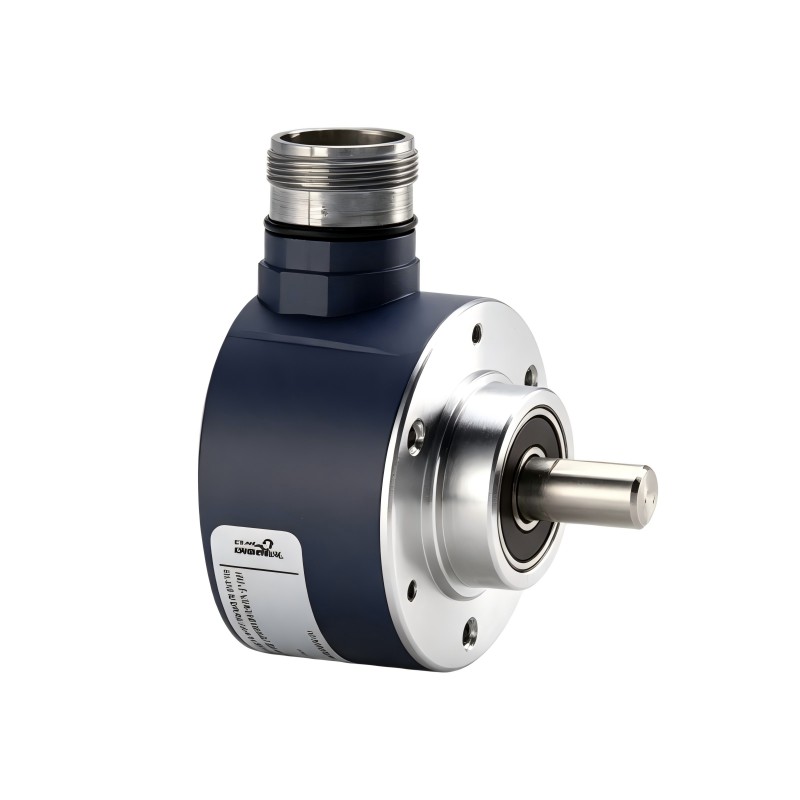
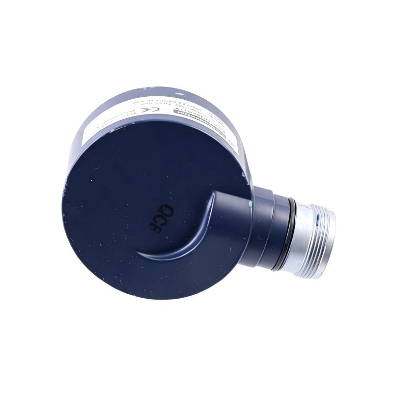
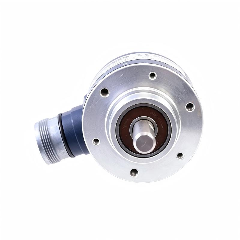
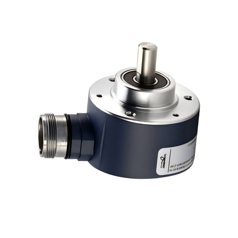
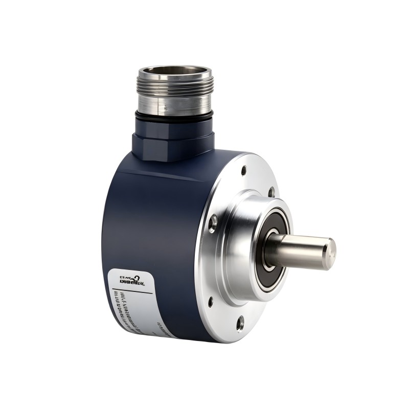
The Schneider XCC-1510PS05X XCC Incremental Encoder is an industrial automation feedback component identified for incremental motion and position measurement applications. Incremental encoders convert mechanical movement into electrical signals that can be processed by compatible controllers, counters, or motion-control equipment.
In industrial automation, encoder feedback helps monitor rotational movement, estimate shaft speed, track relative position, and coordinate machine operations. Depending on the encoder’s electrical output and the capabilities of the receiving system, its signals may support positioning sequences, speed monitoring, synchronization, and general machine-motion supervision.
The Schneider XCC-1510PS05X has a specified diameter of 58 mm and a listed weight of 0.465 kg. These physical specifications are useful when planning installation space, checking mechanical fit, and assessing replacement requirements.
Before installing or replacing this encoder, users should verify its exact output configuration, resolution, supply requirements, connector arrangement, and mechanical mounting details. These characteristics determine whether the device can operate correctly with the intended automation equipment.
2. Technical Specifications
| Parameter | Specification |
|---|---|
| Brand | Schneider Electric |
| Model | XCC-1510PS05X |
| Product Series | XCC |
| Product Type | Incremental Encoder |
| Diameter | 58 mm |
| Weight | 0.465 kg |
| Primary Function | Incremental motion and position feedback |
| Typical Application | Industrial automation and rotational movement monitoring |
| Output Signal Type | Verify from the exact model documentation |
| Resolution | Confirm from the product specification |
| Supply Voltage | Verify before connection |
| Electrical Interface | Confirm compatibility with the receiving device |
| Connection Type | Check the model-specific connector and wiring details |
| Mounting Arrangement | Verify against the mechanical drawing |
| Shaft or Coupling Requirements | Confirm from the applicable installation documentation |
| System Compatibility | Verify against the controller, counter, or drive |
The diameter and weight listed above are the supplied product specifications. Other electrical and mechanical characteristics should be confirmed from the exact product documentation before commissioning.
3. Function and Working Principle
An incremental encoder converts movement into a sequence of electrical signals. When the connected shaft or mechanism rotates, the encoder generates pulses corresponding to the movement detected by its sensing system.
A compatible controller counts and interprets these signals to estimate relative position or rotational speed. Depending on the encoder’s output configuration, the receiving equipment may also determine the direction of rotation.
3.1 Incremental Position Measurement
Incremental encoders provide movement information relative to an established reference. The controller counts pulses to determine how far a shaft or mechanism has moved.
Because incremental feedback generally does not directly provide an absolute position value, a machine may require a homing procedure, reference sensor, or other method to establish its starting position after power-up.
3.2 Rotational Speed Monitoring
The frequency of encoder pulses changes with rotational speed. A suitable controller can process this frequency to estimate how quickly a shaft is rotating.
This information may be used for speed monitoring, movement verification, or control functions supported by the receiving equipment.
3.3 Direction Detection
Some incremental encoder configurations provide phase-related output signals that allow compatible equipment to determine rotational direction. The exact signal arrangement of the XCC-1510PS05X must be verified before designing or modifying the electrical interface.
3.4 Signal Processing
The encoder generates feedback signals, while the connected controller, counter, or drive interprets them. Accurate operation depends on matching the encoder’s output type, electrical signal levels, resolution, and connection requirements to the receiving device.
The specific electrical behavior and supported functions of the XCC-1510PS05X should be confirmed from its model-specific technical documentation.
4. Role in Industrial Automation Systems
Incremental encoders play an important role in systems that require information about rotational movement or relative position. Their performance depends on suitable mechanical installation, correct signal processing, and compatible control equipment.
4.1 Motion Control
In motion-control applications, encoder feedback can help a controller monitor movement and coordinate machine operations. When connected to a compatible drive or motion controller, the feedback may support speed regulation, positioning sequences, or synchronization.
4.2 Relative Position Tracking
Automated machinery frequently needs to determine how far a shaft, roller, or driven component has moved. Incremental pulse counting provides relative movement information that the controller can use to track position from a known reference.
4.3 Machine Synchronization
Production equipment may contain several moving components that must operate in coordination. Encoder feedback can help a control system compare movement and maintain the intended relationship between conveyors, rollers, shafts, or other mechanisms.
4.4 Operational Monitoring
Encoder signals can provide information about movement and rotational speed. When combined with suitable control logic, this information may help identify unexpected stops, movement inconsistencies, or other operating conditions that require attention.
4.5 Equipment Maintenance
Reliable encoder feedback supports troubleshooting and maintenance activities. Technicians can compare reported movement with actual machine behavior to investigate possible faults involving the encoder, cable, mechanical coupling, or receiving controller.
5. Industrial Applications
The Schneider XCC-1510PS05X can be evaluated for applications that require incremental motion feedback, provided its specifications are compatible with the target equipment.
5.1 Manufacturing Machinery
Manufacturing systems use motion feedback to monitor rotating components, coordinate machine cycles, and support repeatable production operations. Incremental encoder signals can provide movement information to a compatible controller.
5.2 Packaging Equipment
Packaging machinery often contains rollers, feed mechanisms, and rotating assemblies that must operate in coordination. Encoder feedback may help monitor movement and support synchronization with programmed machine sequences.
5.3 Conveyor and Material Handling Systems
Conveyors and transfer mechanisms may use encoder signals to estimate movement and monitor operating speed. This information can support movement tracking and coordination with other parts of a material handling line.
5.4 Printing and Converting Machinery
Printing, labeling, and converting equipment can require coordinated movement between rollers and feed mechanisms. A correctly matched encoder can provide movement information used by the control system.
5.5 Automated Assembly Equipment
Assembly machinery may use rotary or linear mechanisms to position components and perform repeated operations. Incremental feedback can help a compatible controller track movement and verify that a mechanism has completed the intended motion.
5.6 General Industrial Motion Monitoring
Incremental encoders can be used in suitable machinery to monitor rotating shafts and other moving components. The suitability of the XCC-1510PS05X depends on its confirmed resolution, output characteristics, mounting arrangement, environmental limits, and interface compatibility.
These examples describe common application areas for appropriately specified incremental encoders and do not establish compatibility with every machine listed.
6. Installation and System Integration
Correct installation is essential for reliable encoder feedback. The following checklist provides general guidance and does not replace the manufacturer’s model-specific instructions.
Step 1: Verify the Model Number
Confirm that the product label identifies the encoder as Schneider XCC-1510PS05X. Compare the model with the equipment documentation, bill of materials, and existing component.
Do not substitute another encoder solely because it has a similar housing diameter or appearance.
Step 2: Isolate the Equipment
Place the machine in a safe condition and isolate the relevant power sources according to the site’s approved lockout/tagout procedure. Verify that the equipment is safe to handle before disconnecting wiring or removing the existing encoder.
Step 3: Inspect the Encoder
Examine the housing, connector, cable entry, mounting surfaces, and mechanical interface for visible damage or contamination. Confirm that the installation area is suitable for the encoder’s mounting arrangement.
Step 4: Verify Mechanical Compatibility
Check the mounting dimensions, shaft or coupling requirements, alignment tolerances, and permitted mechanical loads against the applicable mechanical drawing.
Incorrect alignment or excessive mechanical loading may cause unstable feedback or premature wear.
Step 5: Confirm Electrical Requirements
Identify the required supply voltage, output type, signal levels, connector arrangement, and wiring configuration. Confirm that the receiving controller, counter, or drive supports the encoder’s actual electrical interface.
Do not assume terminal assignments, connector pinouts, or voltage requirements based on the model name alone.
Step 6: Mount the Encoder
Install and secure the encoder according to the approved procedure. Ensure that the mechanical coupling is correctly fitted and that the cable is routed away from sharp edges, excessive tension, and moving machine parts.
Step 7: Check Wiring and Signal Routing
Verify that the wiring matches the approved diagram. Where required by the system design, follow the specified shielding and grounding arrangements and route encoder signal cables appropriately to reduce electrical interference.
Step 8: Restore Power and Test Feedback
After completing the installation and inspection, restore power according to the approved commissioning procedure. Check whether the receiving controller or drive detects valid encoder signals.
Move the mechanism through a controlled test and verify that the reported movement corresponds to actual machine movement.
Step 9: Validate System Operation
Check position tracking, speed measurement, and relevant diagnostic information. Confirm that the feedback remains stable during the required operating conditions before returning the machine to normal operation.
7. Common Problems and Troubleshooting
Encoder problems can originate in the electrical supply, wiring, mechanical installation, controller configuration, or encoder itself. Troubleshooting should proceed systematically.
| Symptom | Possible Causes | Recommended Checks |
|---|---|---|
| Encoder is not detected | Missing supply, incorrect wiring, incompatible input interface, or damaged connector | Verify the supply, connections, and receiving-device compatibility |
| No pulse signal is detected | Connection fault, damaged cable, mechanical issue, or encoder malfunction | Inspect wiring and verify the output using an appropriate test method |
| Position readings are inaccurate | Incorrect scaling, missed pulses, mechanical slippage, or configuration error | Check controller settings, signal quality, and mechanical coupling |
| Direction reading is incorrect | Incorrect signal-channel wiring or controller configuration | Verify the documented output arrangement and receiving-device settings |
| Feedback is intermittent | Loose connector, cable damage, electrical interference, or unstable supply | Inspect the wiring and evaluate signal integrity |
| Speed readings fluctuate | Unstable signal, vibration, poor alignment, or unsuitable processing settings | Check the mechanical installation and signal-processing configuration |
| Fault remains after replacement | The original problem may be outside the encoder | Check the controller, cable, supply, coupling, and configuration |
7.1 Check the Power Supply and Connections
Confirm that the encoder receives the specified supply and that all connections are secure. Inspect the cable and connector for damaged insulation, loose contacts, contamination, or visible mechanical damage.
Perform electrical measurements only with suitable instruments and according to approved safety procedures.
7.2 Verify Signal Compatibility
An encoder may fit mechanically but still be electrically incompatible with the receiving device. Confirm the output type, signal levels, resolution, and input requirements of both devices.
7.3 Inspect Mechanical Installation
Check the mounting arrangement, coupling, shaft alignment, and associated mechanical components. Slippage or excessive vibration may cause readings that do not accurately represent actual movement.
7.4 Review Controller Configuration
Confirm that the receiving device is configured for the correct encoder type and resolution. Incorrect pulse scaling or signal interpretation can result in inaccurate position or speed measurements.
7.5 Investigate Electrical Interference
Noise from motors, drives, switching equipment, or poorly routed cables may affect feedback signals. Review cable routing, shielding, grounding, and installation practices against the approved system design.
7.6 Determine Whether Replacement Is Necessary
If the supply, wiring, mechanical installation, and controller configuration have been checked but the fault persists, further testing or replacement may be required. Use a verified compatible component and follow the site’s equipment change-control procedure.
8. Preventive Maintenance and Reliability
Preventive maintenance can help maintain stable feedback and reduce unexpected machine downtime.
- Inspect mounting hardware: Check for looseness, damage, and signs of vibration.
- Check mechanical coupling: Confirm that alignment and engagement remain within the specified limits.
- Examine cables and connectors: Look for abrasion, crushing, contamination, and loose connections.
- Monitor feedback quality: Investigate unexpected changes in pulse signals, position readings, or speed measurements.
- Review operating conditions: Confirm that temperature, vibration, dust, moisture, and other environmental conditions meet the product requirements.
- Maintain configuration records: Keep the encoder model, controller settings, and approved wiring diagrams available.
- Use approved replacement parts: Verify electrical and mechanical compatibility before replacing the encoder.
- Follow safe maintenance procedures: Isolate the equipment and follow approved installation and handling instructions.
Maintenance intervals should be based on the manufacturer’s recommendations, machine operating conditions, and the criticality of the application.
9. Compatible System Components
The XCC-1510PS05X should be evaluated as part of the complete feedback system. The following table lists component categories that may require verification during integration; it does not confirm compatibility with specific part numbers.
| Component Category | Integration Considerations |
|---|---|
| PLC or industrial controller | Confirm support for the encoder’s signal type and required input processing |
| High-speed counter module | Verify supported signal format and counting capability |
| Motion controller | Confirm feedback-interface compatibility and configuration requirements |
| Motor drive or motion drive | Check whether the drive supports the encoder output directly or requires an approved interface |
| Coupling or mechanical adapter | Verify shaft dimensions, alignment, mounting, and mechanical loading |
| Signal cable and connector | Confirm connector type, wiring arrangement, and cable specifications |
| Power supply | Verify rated voltage and current requirements |
| Engineering software | Confirm support for the required feedback configuration |
Compatibility should be established using the complete system arrangement and the applicable technical documentation.
10. Replacement and Alternative Encoder Selection
When replacing the Schneider XCC-1510PS05X, engineers should compare its functional, electrical, and mechanical characteristics with those of the proposed replacement.
| Selection Factor | What to Verify |
|---|---|
| Exact model | Confirm XCC-1510PS05X and any relevant product revision |
| Encoder type | Confirm incremental operation |
| Housing diameter | Compare with the supplied 58 mm specification and the mounting drawing |
| Weight | Check handling and mounting requirements against the listed 0.465 kg |
| Resolution | Ensure the replacement meets the required pulse-counting resolution |
| Output configuration | Verify signal arrangement and electrical characteristics |
| Supply requirements | Confirm the rated voltage and current |
| Mechanical interface | Check mounting dimensions, shaft or coupling arrangement, and alignment |
| Environmental specifications | Verify suitability for the operating environment |
| Receiving-device compatibility | Confirm support from the controller, counter, or drive |
| Commissioning requirements | Determine whether configuration changes or functional validation are necessary |
A replacement should not be selected based solely on a similar diameter or product description. Its electrical interface, resolution, mechanical arrangement, and system compatibility must also be confirmed.
11. Key Benefits of Correct Encoder Selection
When correctly specified and integrated, an incremental encoder can support reliable motion monitoring and feedback in industrial automation systems.
Relative position feedback: Pulse counting allows compatible equipment to track movement from an established reference.
Speed monitoring: Pulse frequency can provide information about rotational speed when processed by a suitable controller.
Motion coordination: Encoder feedback can help coordinate machine components when supported by the control architecture.
Maintenance support: Consistent feedback information can help technicians investigate movement-related faults.
Mechanical planning: The supplied 58 mm diameter and 0.465 kg weight provide useful information for installation-space and handling assessments.
System integration: Matching electrical and mechanical specifications reduces the risk of incompatible connections and unreliable feedback.
Actual performance depends on the verified encoder specifications, installation quality, and capabilities of the receiving control system.
12. Technical FAQs
Q1: What is the Schneider XCC-1510PS05X?
The Schneider XCC-1510PS05X is identified in the supplied product information as an XCC incremental encoder. Its exact output and electrical characteristics should be verified before installation.
Q2: What is the diameter of the XCC-1510PS05X?
The supplied product diameter is 58 mm. Confirm the complete mounting dimensions before selecting mounting hardware or planning a replacement.
Q3: How much does the XCC-1510PS05X weigh?
The supplied product weight is 0.465 kg.
Q4: What is an incremental encoder used for?
An incremental encoder generates electrical signals corresponding to movement. Compatible control equipment can use these signals to track relative position, estimate rotational speed, and determine direction where the output configuration supports it.
Q5: Does an incremental encoder provide absolute position after power-up?
Generally, no. Incremental encoders normally track movement relative to a reference. Depending on the application, the control system may need a homing sequence or reference sensor to establish a known position after startup.
Q6: Can the XCC-1510PS05X connect directly to any PLC?
No. Direct connection depends on the encoder’s output type, signal levels, supply requirements, and the PLC’s supported input interface.
Q7: What should be checked before replacing the encoder?
Verify the complete model number, resolution, output configuration, supply requirements, connector arrangement, mechanical interface, and compatibility with the receiving controller or drive.
Q8: Why might an encoder provide inaccurate position readings?
Possible causes include missed pulses, electrical interference, incorrect resolution settings, mechanical slippage, wiring problems, or an incompatible input interface. Both the mechanical installation and electrical signal path should be checked.
Q9: Can another 58 mm encoder replace the XCC-1510PS05X?
Not automatically. A replacement must also match the required resolution, output configuration, electrical requirements, mounting arrangement, and control-system interface.
Q10: What should be done if the encoder signal is intermittent?
Inspect the wiring, connectors, mounting, and coupling. Verify the supply and signal quality, and investigate electrical interference or controller configuration. Replace the encoder only after other likely causes have been assessed.
13. Conclusion
The Schneider XCC-1510PS05X XCC Incremental Encoder is an industrial feedback component identified for incremental motion and position measurement applications. Its supplied diameter of 58 mm and weight of 0.465 kg provide useful information for product identification, installation planning, and replacement assessment.
For dependable operation, engineers should verify the encoder’s resolution, output configuration, supply requirements, mechanical interface, and compatibility with the connected control equipment before installation. Correct mounting, appropriate wiring, systematic commissioning, and regular maintenance can help support reliable feedback and reduce avoidable downtime in industrial automation systems.