

ProductPRODUCT
Featured products
Contact Us
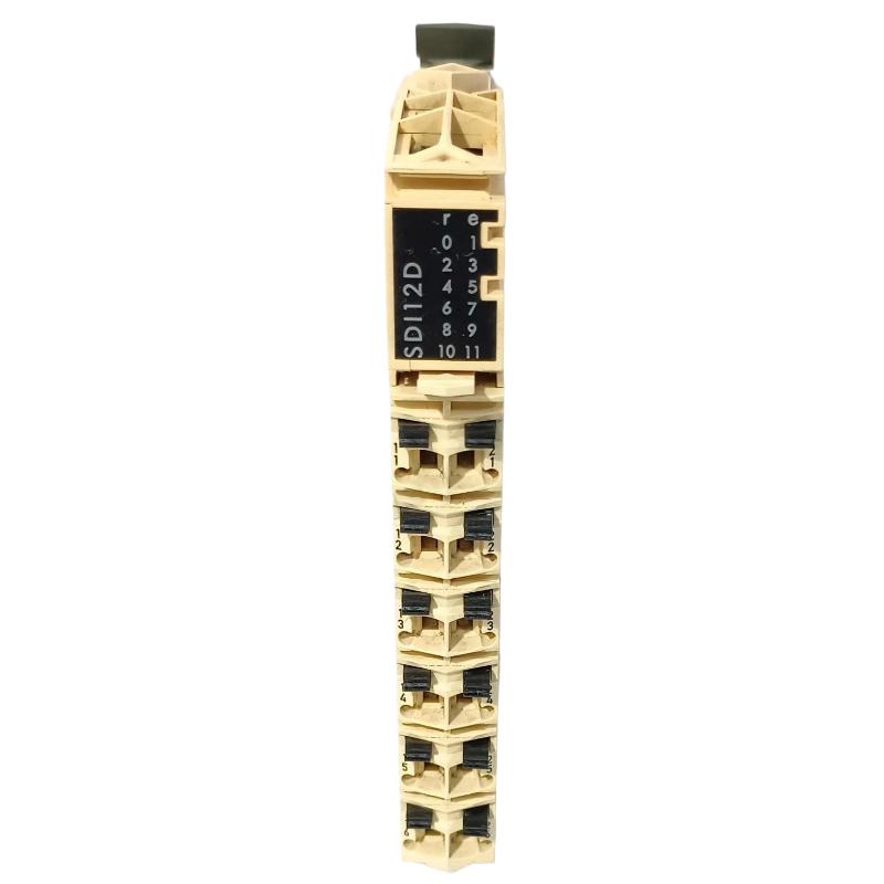
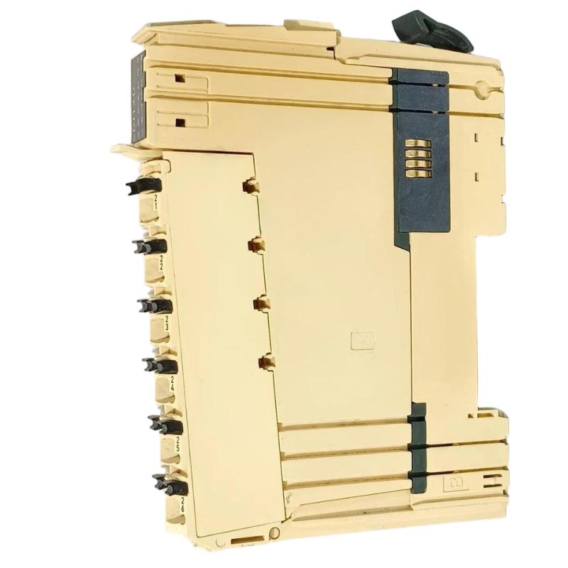
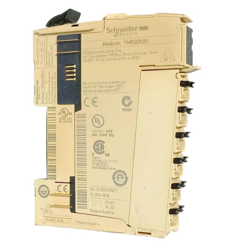
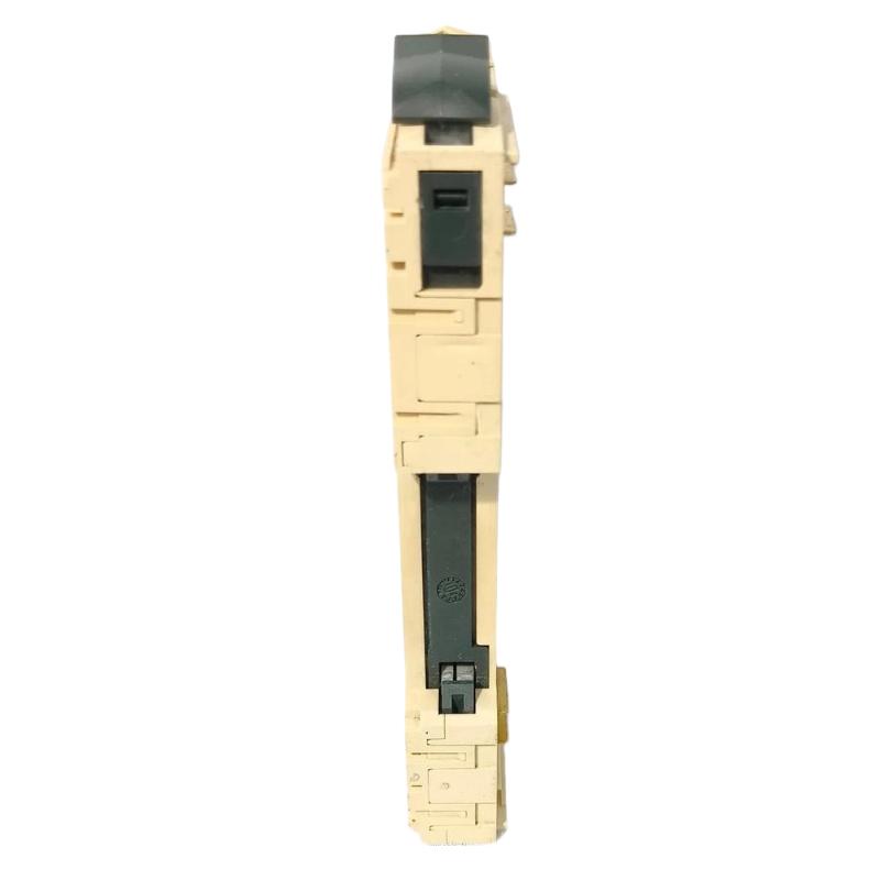
- Schneider
- TM5SDI12D
- Discrete Input Module
- France
- 99 × 12.5 × 75 mm
- 0.025 kg
- Xiamen, China
- New & In Stock
- T/T, PayPal, Western Union
- 1 Year
- 1-3 Working Days
- DHL, UPS, TNT, FedEx and EMS.
- 24-Hour Service
- COO
- 5
Our advantage

Global Logistics
We have a 10-year logistics and express cooperation agreement, so our products can be shipped to any place in the world.

Brand new and original
Our products are imported in bulk from the place of origin. Because of the cooperative relationship, our products are all original and 100% new.

24-hour service
We provide 7*24 hours service to our customers. We will be there whenever you need us.

Price advantage
All our products are priced very favorably because we have our own warehouse and supply.
| Company Information | |||
| [email protected] | |||
| Mobile | +8615980777398 | ||
| +8615980777398 | |||
| 15980777398 |
1. Product Overview
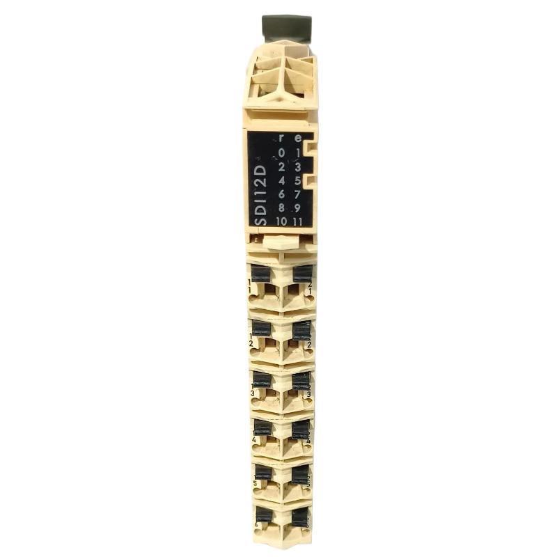
The Schneider TM5SDI12D Discrete Input Module is identified as a digital input component for industrial automation applications. Discrete input modules are used to acquire binary signals from field devices and make the corresponding input states available to a control system. Depending on the installed platform, these signals may represent conditions such as machine status, switch positions, equipment interlocks, or sensor states.
In an automated production line or process-control installation, input signals allow the controller to monitor field conditions and execute programmed logic. Correct module selection, wiring, and configuration are therefore important for reliable machine operation and accurate status monitoring.
The TM5SDI12D can be evaluated for applications requiring discrete signal acquisition, subject to confirmation of its exact electrical specifications and supported hardware configuration. Its supplied dimensions are 99 × 12.5 × 75 mm, and its listed weight is 0.025 kg, making these details useful for product identification and preliminary cabinet-layout planning.
Before installation or replacement, engineers should confirm the module’s input-channel count, supported signal voltage, input characteristics, terminal assignments, and compatibility with the existing controller and I/O system. These specifications should not be inferred from the model number alone.
2. Technical Specifications
| Parameter | Specification |
|---|---|
| Brand | Schneider Electric |
| Model | TM5SDI12D |
| Product Type | Discrete Input Module |
| Signal Type | Digital/discrete input, subject to model verification |
| Dimensions | 99 × 12.5 × 75 mm |
| Weight | 0.025 kg |
| Input Channel Count | Verify against the exact product documentation |
| Rated Input Voltage | Confirm before connecting field devices |
| Input Current | Verify from the technical specifications |
| Input Logic and Thresholds | Confirm the supported electrical characteristics |
| Connection Method | Follow the approved wiring diagram |
| System Compatibility | Verify the controller, base, associated modules, and engineering configuration |
The dimensions and weight above are based on the supplied product information. The precise channel count, voltage rating, input thresholds, response time, isolation characteristics, and supported hardware combinations must be verified before commissioning.
3. Function and Working Principle
A discrete input module receives binary electrical signals from field devices and presents the corresponding states to a control system. Unlike an analog input module, which measures a changing value such as temperature or pressure, a discrete input module generally distinguishes between defined signal states, commonly represented as ON and OFF.
A typical signal path includes a field device, input wiring, the discrete input module, and a controller that processes the resulting status information.
Signal Acquisition
A field device changes its electrical output according to the condition being monitored. Depending on the device and input design, this may indicate that a limit switch has operated, a sensor has detected an object, or an auxiliary contact has changed state.
Input-State Processing
The module interprets the incoming electrical signal according to its designed input characteristics. The resulting state is made available to the automation system through the supported I/O architecture.
Controller Logic
The controller uses the input state in its application program. For example, a machine sequence may wait for a position switch, monitor a safety-related status through an appropriate certified system, or prevent an operation when a required process condition is absent.
A standard discrete input module should not automatically be treated as a safety-rated input device. Safety functions must use hardware and architectures specifically approved for the required safety application.
Diagnostic Monitoring
Depending on the product and system configuration, diagnostics may help engineers identify module faults, wiring problems, or abnormal operating conditions. The available diagnostic functions should be confirmed for the exact model.
4. Role in Industrial Automation Systems
Machine Status Monitoring
Discrete inputs provide the controller with information about machine states, equipment positions, and operational conditions. This information supports programmed sequences and equipment monitoring.
Sensor Integration
Industrial sensors often provide switching outputs that indicate the presence or absence of an object or a particular operating condition. A compatible input module allows these signals to be incorporated into the control program.
Interlock and Permissive Logic
Controllers commonly use discrete status signals to determine whether an operation is permitted. Examples include confirming that a guard is closed, a component is in position, or a prerequisite process step has been completed. Safety-related functions require an appropriately rated safety system.
Process Sequence Control
In automated processes, input signals can indicate when a step has finished or when a process condition has changed. The controller uses these states to advance sequences, activate outputs, or report alarms.
Equipment Diagnostics
Input-state monitoring can help maintenance personnel determine whether a field device has changed state as expected. Comparing physical conditions with the controller’s input data can help isolate sensor, wiring, or configuration problems.
5. Industrial Applications
The TM5SDI12D may be considered for suitable discrete signal-acquisition applications after its electrical ratings and system compatibility have been verified.
Manufacturing and Assembly Lines
Assembly equipment uses limit switches, proximity sensors, and other switching devices to monitor component positions and machine states. Discrete input signals support sequencing and coordination between machine operations.
Packaging Machinery
Packaging equipment relies on position detection, product-presence signals, and equipment-status monitoring. Properly configured digital inputs help controllers respond to field conditions and manage machine sequences.
Material Handling Systems
Conveyors, transfer stations, and sorting equipment use discrete signals to detect material presence, monitor position switches, and track operational states. Input wiring and sensor compatibility must match the module’s specifications.
Process Automation
Process equipment may use discrete contacts and switching sensors to indicate valve position, pump status, equipment availability, or alarm conditions. The module must be suitable for the electrical characteristics of the connected devices.
OEM Machinery
Original equipment manufacturers often integrate discrete input modules into control panels to collect field signals and simplify machine control. Accurate documentation and consistent wiring practices make future maintenance easier.
These examples describe general applications for compatible discrete input modules. The specific suitability of the TM5SDI12D depends on its verified specifications and the requirements of the installation.
6. Installation and System Integration
Correct installation helps prevent false input states, electrical damage, and unexpected machine behavior. The following procedure is a general checklist; the manufacturer’s instructions and approved wiring diagrams take precedence.
Step 1: Verify the Product
Confirm that the complete model number is TM5SDI12D. Check the product label, supplied documentation, and system bill of materials. Do not substitute a similar model without verifying its electrical and functional equivalence.
Step 2: Isolate the Equipment
Place the machine in a safe condition and isolate the relevant power sources according to the site’s lockout/tagout procedure. Verify that the circuit is de-energized before installing or disconnecting the module.
Step 3: Confirm the Electrical Specifications
Determine the module’s supported input voltage, current requirements, input thresholds, and wiring arrangement. Ensure that the connected sensors or contacts are electrically compatible.
Do not connect field wiring until the exact input specifications have been confirmed.
Step 4: Inspect the Module and Mounting Location
Check the housing, terminals, connectors, and mounting area for visible damage or contamination. Confirm that the module is installed using the approved method for its hardware platform.
Step 5: Connect the Field Devices
Follow the model-specific wiring diagram to connect each field device to its designated input. Verify polarity where applicable, common-terminal arrangements, and any required supply connections.
Keep signal wiring organized and follow the manufacturer’s grounding, shielding, and cable-routing recommendations.
Step 6: Verify Input Assignments
Check that each physical input corresponds to the correct controller address, variable, or software assignment. Incorrect mapping can cause the controller program to interpret a field signal as a different machine condition.
Step 7: Restore Power and Check Status
After reviewing the wiring, restore power according to the approved commissioning procedure. Observe available status indicators and check the controller’s diagnostic information.
Step 8: Test Each Input
Operate each connected field device under controlled conditions and confirm that the expected input state appears in the engineering software. Verify both the active and inactive states where applicable.
Step 9: Complete Functional Validation
Confirm that the controller responds correctly to the tested inputs and that the overall sequence operates as intended. Complete required interlock and operational checks before returning the machine to normal service.
7. Troubleshooting Common Problems
Discrete input faults may originate in the field device, wiring, power supply, module, controller configuration, or software logic. A systematic approach helps isolate the cause.
| Symptom | Possible Cause | Recommended Action |
|---|---|---|
| Input remains OFF | No field signal, incorrect wiring, incompatible voltage, or faulty sensor | Verify the field device, wiring diagram, and input electrical requirements |
| Input remains ON | Short circuit, incorrect common connection, or field device held active | Inspect wiring and verify the physical state of the device |
| Input changes intermittently | Loose terminal, damaged cable, electrical interference, or unstable signal | Inspect connections and cable routing; evaluate the electrical environment |
| Controller does not display the expected input state | Incorrect I/O mapping, configuration problem, or unsupported module arrangement | Check the hardware configuration, address assignment, and diagnostics |
| Multiple inputs fail together | Shared supply, common wiring, or system-level issue | Check common connections, supply distribution, and related hardware |
| Module reports a diagnostic fault | Hardware, connection, or configuration issue | Record the diagnostic message and follow the model-specific troubleshooting procedure |
7.1 Check the Field Device
Verify that the sensor or contact operates correctly and produces the expected electrical signal. A mechanically operated switch may be misaligned, while an electronic sensor may require a compatible supply or output connection.
7.2 Inspect Wiring and Terminals
Check for loose terminals, damaged insulation, broken conductors, incorrect polarity, or an incorrect common connection. Perform continuity and voltage checks only when safe and appropriate.
7.3 Verify Input Voltage
Measure the signal using suitable instruments and compare the result with the module’s documented input range and thresholds. Never assume that all discrete input modules accept the same voltage.
7.4 Review I/O Mapping and Software Logic
If the electrical signal is present but the controller shows an unexpected state, verify the module configuration, input address, variable mapping, and program logic.
7.5 Investigate Shared Faults
If several inputs fail simultaneously, investigate shared power supplies, common terminals, connectors, and configuration issues before assuming that multiple channels have failed independently.
7.6 Determine Whether the Module Requires Replacement
If the field signal, wiring, electrical characteristics, and configuration have been verified but the input still behaves incorrectly, further testing or module replacement may be necessary. Use an approved replacement and document the change.
8. Maintenance and Reliability Recommendations
Preventive maintenance can help improve signal reliability and reduce unplanned downtime.
- Inspect terminals: Check field wiring and connections during scheduled maintenance.
- Check sensor condition: Inspect connected switches and sensors for wear, misalignment, contamination, or damage.
- Maintain cabinet conditions: Keep the enclosure clean and within the specified environmental limits.
- Review diagnostics: Record recurring input faults and investigate their underlying causes.
- Verify I/O documentation: Keep channel assignments, wiring diagrams, and controller variables up to date.
- Protect spare modules: Store replacement components in appropriate conditions and follow electrostatic-discharge precautions.
- Test functional responses: Confirm that important input signals produce the expected controller behavior during approved maintenance activities.
- Document replacements: Record the installed model number and any configuration changes.
Maintenance frequency should reflect the operating environment, equipment criticality, and site maintenance policy.
9. Compatible System Components
The following component categories are commonly considered when integrating a discrete input module. Exact compatibility with the TM5SDI12D must be confirmed.
| Component Category | Integration Considerations |
|---|---|
| Controller or CPU | Verify supported hardware platform, firmware, and I/O configuration |
| Digital sensors | Match output type, voltage, current, and switching characteristics |
| Mechanical switches and contacts | Confirm the input circuit supports the device’s electrical characteristics |
| Power supply | Verify the supply requirements of the module and connected field devices |
| Mounting or base components | Confirm mechanical compatibility with the installed system |
| Field wiring and connectors | Follow the specified terminal arrangement and cable requirements |
| Engineering software | Confirm support for the module and correct input mapping |
Do not assume that a module is compatible with a particular controller or sensor solely because both products are from the same manufacturer.
10. Replacement and Alternative Selection
When selecting a replacement for the Schneider TM5SDI12D Discrete Input Module, evaluate electrical and functional compatibility before considering physical dimensions or cost.
| Selection Factor | What to Verify |
|---|---|
| Exact model | Confirm TM5SDI12D and any relevant hardware revision |
| Input channel count | Match the required number of discrete inputs |
| Input voltage | Confirm compatibility with the connected field devices |
| Input characteristics | Compare current requirements, thresholds, and supported signal types |
| Wiring arrangement | Verify terminal layout, common connections, and connector compatibility |
| Controller support | Confirm compatibility with the existing hardware and engineering environment |
| Physical dimensions | Check mounting requirements and cabinet clearance |
| Configuration changes | Determine whether addresses, variables, or controller settings must be updated |
A replacement with similar dimensions may have different input characteristics or a different channel arrangement. Confirm technical equivalence before installing an alternative.
11. Key Advantages of Correct Discrete Input Integration
Reliable field-state monitoring: A properly selected and installed input module allows compatible field signals to be represented accurately in the control system.
Improved sequence control: Discrete input data can support machine sequencing, equipment-status monitoring, and process interlocks.
Simplified fault diagnosis: Comparing the physical device state with the controller’s input state helps maintenance teams identify signal-path problems.
Organized system integration: Correct channel assignments and wiring documentation make the control system easier to maintain.
Efficient cabinet planning: The supplied dimensions of 99 × 12.5 × 75 mm support preliminary space planning, subject to confirmation of the actual hardware.
Low listed weight: The supplied weight of 0.025 kg can be used for preliminary inventory and layout records.
Actual performance depends on the verified product specifications, the connected field devices, and the overall system design.
12. Technical FAQs
Q1: What is the Schneider TM5SDI12D?
It is identified in the supplied product information as a Schneider Discrete Input Module. Discrete input modules generally receive binary signals from field devices for use by a controller. The exact specifications of this model should be confirmed before integration.
Q2: What are the dimensions of the TM5SDI12D?
The supplied dimensions are 99 × 12.5 × 75 mm.
Q3: What is the weight of the TM5SDI12D?
The supplied product weight is 0.025 kg.
Q4: What devices can connect to a discrete input module?
Depending on the module’s electrical specifications, typical devices may include compatible proximity sensors, limit switches, pushbuttons, and auxiliary contacts. Check output type, voltage, current, and wiring requirements before connecting a device.
Q5: How can an input that remains OFF be diagnosed?
Check whether the field device is producing the expected signal, inspect the wiring, verify the supply and input voltage, and confirm the controller’s I/O mapping.
Q6: Why might an input signal change intermittently?
Possible causes include loose terminals, damaged cables, unstable power, electrical interference, or an unreliable field device. Investigate the entire signal path.
Q7: Can the TM5SDI12D be used for safety functions?
Do not assume that a standard discrete input module is safety-rated. Safety-related applications require hardware and system designs that meet the applicable safety requirements.
Q8: What should be checked before replacing the module?
Verify the complete model number, input specifications, channel count, wiring arrangement, controller compatibility, and configuration requirements.
Q9: Does replacing the module require controller reconfiguration?
It depends on the system architecture and whether the replacement is technically equivalent. Confirm the hardware configuration and input assignments, then perform the required commissioning checks.
13. Conclusion
The Schneider TM5SDI12D Discrete Input Module is identified as an industrial automation component for discrete signal acquisition. In a compatible control system, discrete inputs allow controllers to monitor field-device states and use this information in machine sequences, equipment monitoring, and process logic.
The supplied dimensions are 99 × 12.5 × 75 mm, and the listed weight is 0.025 kg. Before installation or replacement, engineers should confirm the module’s exact input characteristics, voltage rating, channel count, wiring arrangement, and controller compatibility.
Correct installation, careful input testing, accurate I/O mapping, and preventive maintenance help support reliable signal acquisition and stable industrial automation operation.