

ProductPRODUCT
Featured products
Contact Us
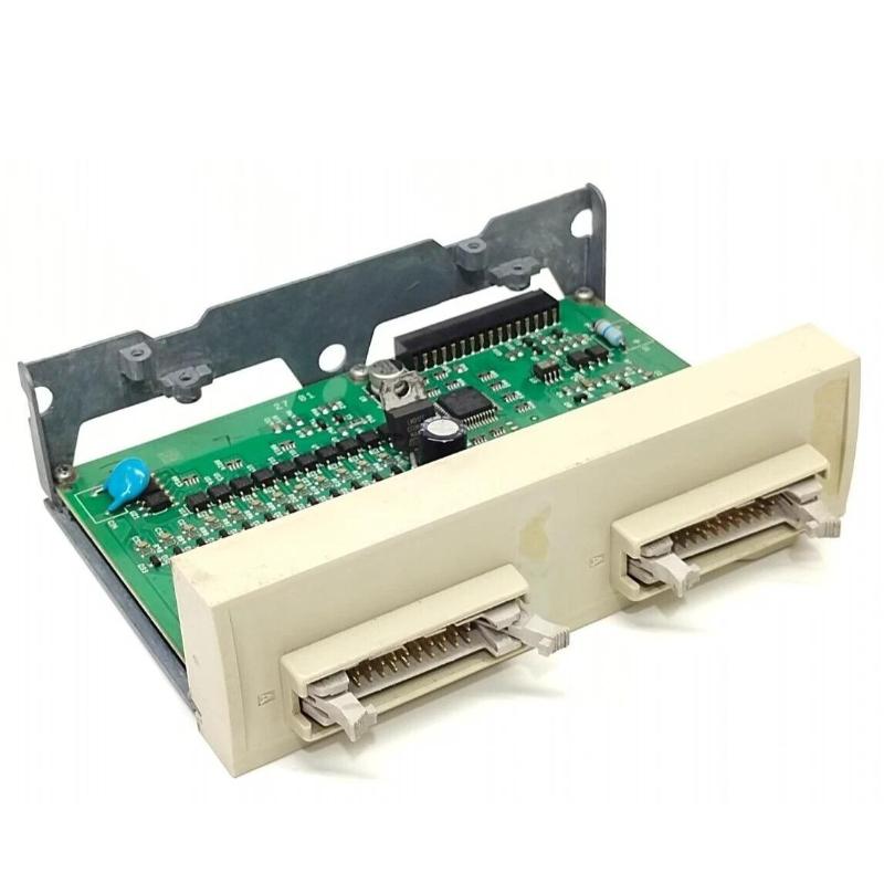
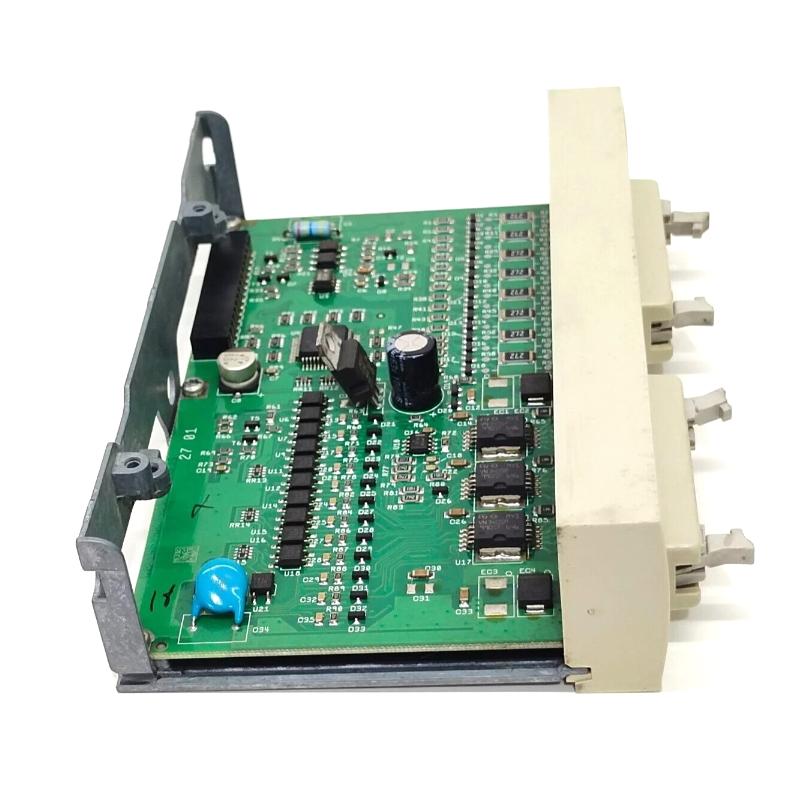
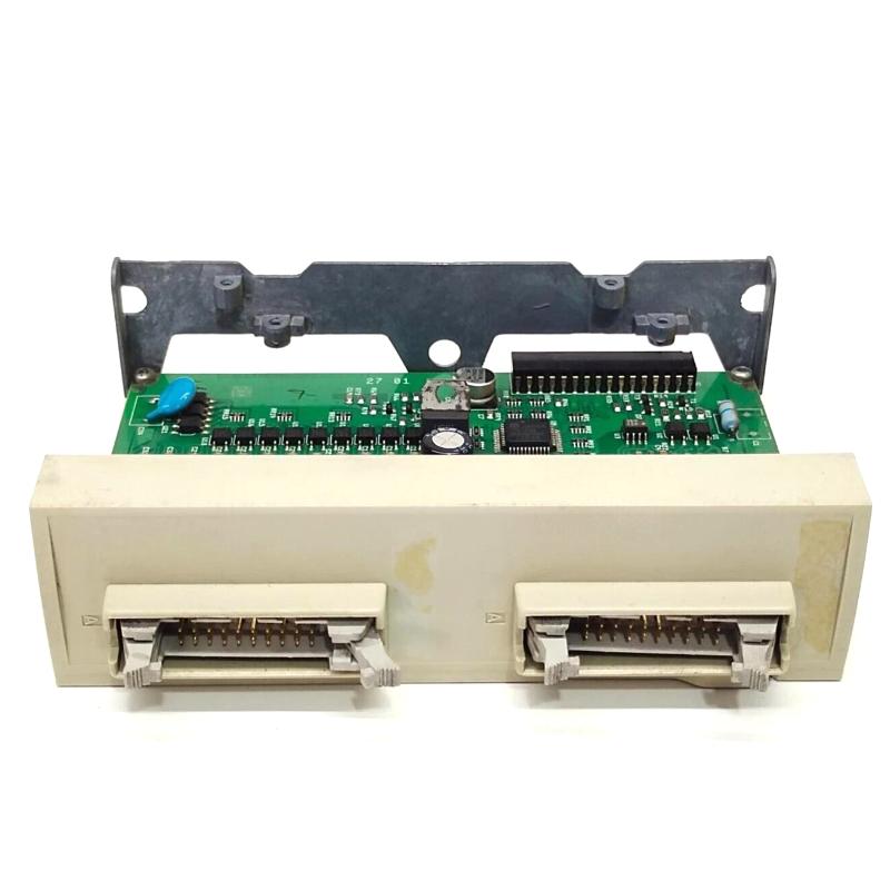
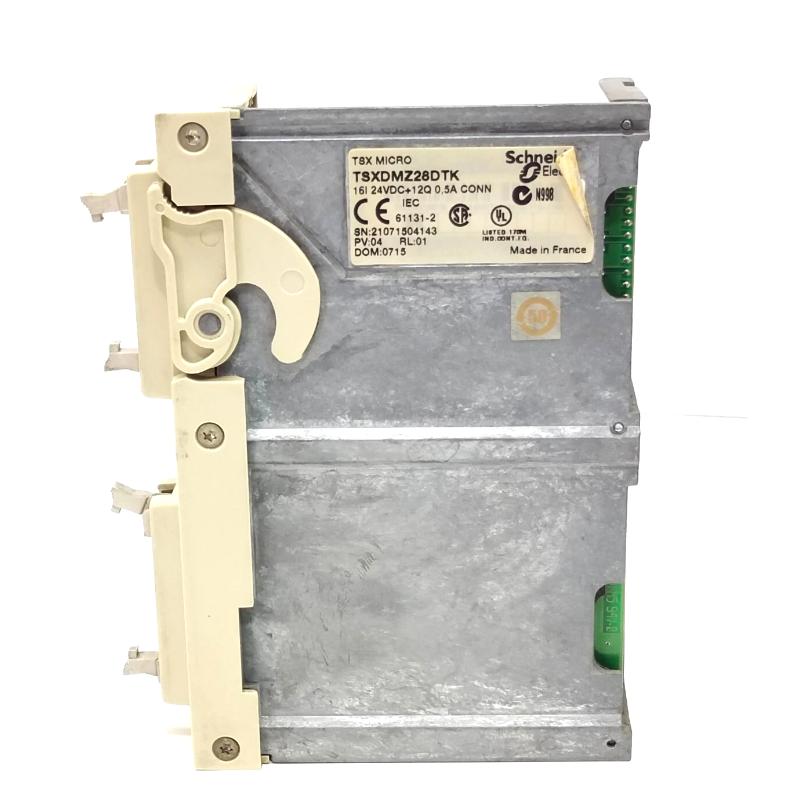
- Schneider
- TSXDMZ28DTK
- Discrete Solid State I/O Base DC
- France
- 180 × 260 × 55 mm
- 0.33 kg
- Xiamen, China
- New & In Stock
- T/T, PayPal, Western Union
- 1 Year
- 1-3 Working Days
- DHL, UPS, TNT, FedEx and EMS.
- 24-Hour Service
- COO
- 6
Our advantage

Global Logistics
We have a 10-year logistics and express cooperation agreement, so our products can be shipped to any place in the world.

Brand new and original
Our products are imported in bulk from the place of origin. Because of the cooperative relationship, our products are all original and 100% new.

24-hour service
We provide 7*24 hours service to our customers. We will be there whenever you need us.

Price advantage
All our products are priced very favorably because we have our own warehouse and supply.
| Company Information | |||
| [email protected] | |||
| Mobile | +8615980777398 | ||
| +8615980777398 | |||
| 15980777398 |
Product Overview
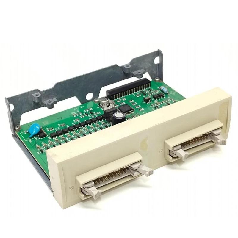
The Schneider TSXDMZ28DTK Modicon TSX Micro Discrete Solid State I/O Base DC combines 16 discrete inputs and 12 solid-state DC outputs in one module for compatible Modicon TSX Micro PLC systems. This arrangement allows the controller to collect signals from field sensors while switching DC loads used in machine sequences, material handling and automated equipment.
The 16 inputs accept 24 V DC positive-logic signals from compatible 2-wire and 3-wire proximity sensors and other switching devices. The 12 outputs use solid-state switching with a nominal 24 V DC output supply, supporting connected loads that meet the specified electrical limits. Input acquisition and output switching are handled through separate channel groups, allowing the PLC program to process machine status and issue actuator commands through the same module.
The module uses HE-10 connectors for grouped signal connections. Its input response can be configured from 0.1 to 7.5 ms, while the specified output response is up to 0.5 ms for state transitions. These characteristics are relevant when designing the sequence timing for equipment that combines sensor feedback with frequent DC output switching.
Technical Specifications
| Parameter | Specification |
|---|---|
| Manufacturer | Schneider Electric |
| Model | TSXDMZ28DTK |
| Product Series | Modicon TSX Micro |
| Product Type | Discrete Solid-State I/O Base DC |
| Total I/O Points | 28 |
| Number of Inputs | 16 |
| Number of Outputs | 12 |
| Input Voltage | 24 V DC positive logic |
| Input Type | Resistive |
| Input Current | 7 mA |
| Input Voltage Range | 19–30 V DC |
| Guaranteed Logic State 1 Voltage | ≥ 11 V |
| Guaranteed Logic State 0 Voltage | < 5 V |
| Guaranteed Logic State 1 Current | ≥ 2.5 mA |
| Guaranteed Logic State 0 Current | ≤ 1.5 mA |
| Input Impedance | 3.4 kΩ |
| Input Response Time | 0.1–7.5 ms |
| Output Type | Solid-state DC output |
| Output Voltage | 24 V DC |
| Output Logic | Positive logic |
| Rated Output Current | 0.5 A per output |
| Maximum Output Current Limit | 0.625 A |
| Output Response Time | ≤ 0.5 ms for state transitions |
| Maximum Output Leakage Current | ≤ 0.5 mA in the OFF state |
| Sensor Compatibility | 2-wire and 3-wire proximity sensors |
| Electrical Connection | HE-10 connectors |
| Current Consumption | 132 mA |
| Power Dissipation | 5 W input; 3.5 W for module outputs plus 0.15 W per active output channel |
| Dimensions | 180 × 260 × 55 mm |
| Weight | 0.33 kg |
Product Features
- 28-point combined I/O: Integrates 16 discrete inputs and 12 solid-state outputs in one module.
- 24 V DC input interface: Acquires positive-logic signals from compatible industrial sensors and switching devices.
- Solid-state output switching: Controls compatible DC loads without mechanical output contacts.
- 0.5 A output rating: Supports individual loads within the specified output-current limits.
- Configurable input response: Allows response settings from 0.1 to 7.5 ms to suit signal characteristics and sequence requirements.
- Fast output response: Provides an output response time of up to 0.5 ms under specified conditions.
- Proximity sensor compatibility: Supports compatible 2-wire and 3-wire proximity sensors.
- HE-10 connections: Groups input and output signals through compatible multiway connectors.
- Separate input and output functions: Allows field feedback and actuator commands to be managed through distinct channel groups.
- TSX Micro integration: Supports combined discrete signal acquisition and output control in compatible Modicon TSX Micro installations.
Working Principle
The TSXDMZ28DTK receives field signals through its 16 input channels. Each input evaluates the incoming 24 V DC signal against the module’s specified voltage and current thresholds. Once the signal is recognized as ON or OFF, the corresponding input state becomes available to the TSX Micro PLC program.
The input response time is configurable from 0.1 to 7.5 ms. This setting affects how input transitions are recognized and should be selected according to the sensor output and machine operating sequence. Sensors whose leakage current or residual voltage falls outside the module’s guaranteed logic limits can cause false states or missed transitions.
The module’s 12 solid-state outputs switch compatible 24 V DC loads according to commands from the PLC. Each output has a rated current of 0.5 A, with a stated maximum current limit of 0.625 A. These limits must not be treated as interchangeable continuous ratings. Load current, switching frequency and the characteristics of inductive devices need to be considered during system design.
When an output command is issued, the corresponding solid-state channel changes state and supplies the connected load according to the output circuit arrangement. During commissioning, each output should be tested under its intended load. If an actuator fails to respond, check the PLC command, output supply, connector wiring and load current before attributing the fault to the module.
Role in a Modicon TSX Micro Control Architecture
The TSXDMZ28DTK serves as a combined field-interface layer in a Modicon TSX Micro automation system. Its input channels deliver sensor information to the PLC, while its output channels switch compatible DC loads in response to the controller’s application logic. This arrangement is useful when a machine requires several feedback signals and actuator commands within the same I/O group.
| System Component | Function | Relationship to the TSXDMZ28DTK |
|---|---|---|
| Modicon TSX Micro PLC | Executes control logic and sequencing | Reads the 16 input states and commands the 12 outputs |
| 24 V DC Power Supply | Supplies field devices and output circuits | Must meet the voltage and current requirements of the connected circuits |
| Proximity Sensor | Detects targets or component presence | Sends a compatible discrete signal to an input channel |
| Limit Switch | Detects a mechanical position or end condition | Provides status feedback to the PLC |
| Photoelectric Sensor | Detects products or material movement | Supplies object-detection signals to the input group |
| DC Solenoid Valve | Operates a pneumatic or hydraulic function | Can be switched through a compatible output circuit within its rating |
| Indicator Lamp | Displays machine or process status | Can be controlled by a compatible DC output |
| Interface Relay | Switches an external circuit | Can isolate or adapt a load circuit when direct output switching is unsuitable |
| HE-10 Connection Cable | Carries grouped I/O signals | Connects the module to compatible field wiring |
| PLC Application Program | Coordinates machine operations | Uses input states to determine when outputs should switch |
Industrial Applications
| Application | Operating Requirement | Role of the TSXDMZ28DTK |
|---|---|---|
| Packaging Machinery | Detect product position and operate small mechanisms | Combines sensor acquisition and DC output switching for machine sequences |
| Conveyor Transfer Stations | Monitor transfer points and control stops or diverters | Reads detection signals and switches compatible output loads |
| Assembly Equipment | Confirm part presence and actuate fixtures | Supplies input states and output commands for assembly sequences |
| Pneumatic Handling Systems | Detect cylinder positions and operate valves | Collects sensor feedback and controls compatible DC solenoid loads |
| Component Feeding Machines | Detect component availability and control feed mechanisms | Coordinates discrete sensor signals with output commands |
| Automated Inspection Fixtures | Acquire part-status signals and operate indicators | Provides I/O for inspection and handling sequences |
| Material Handling Equipment | Monitor limit conditions and control auxiliary devices | Supports sensor-based machine coordination |
| Compact Machine Control Panels | Consolidate discrete signals in a limited I/O arrangement | Combines 16 inputs and 12 outputs in one TSX Micro module |
Installation and Maintenance
- Verify the module reference: Confirm that the installed module is TSXDMZ28DTK and that the Modicon TSX Micro configuration supports the intended I/O arrangement.
- Check the input supply: Ensure connected sensors provide compatible 24 V DC positive-logic signals within the specified voltage range.
- Inspect the HE-10 connectors: Check connector alignment, pin condition and secure mating before energizing the system.
- Verify output power wiring: Confirm that the output supply is connected according to the module’s electrical connection requirements.
- Check output load current: Ensure each connected load stays within the rated 0.5 A output current and the applicable maximum limits.
- Confirm sensor compatibility: Verify sensor output type, leakage current and residual voltage against the module’s guaranteed input thresholds.
- Review channel assignments: Match each field sensor and actuator to the correct connector pin and PLC address using the electrical drawings.
- Test the input channels: Operate each sensor or switch and confirm that the corresponding input state appears correctly in the PLC application.
- Test the output channels: Command each output individually and confirm that the connected load switches as expected.
- Assess inductive loads: Check the suppression requirements for solenoids, relays and other inductive devices to control switching transients.
- Investigate unexpected states: Check the field supply, connector contacts, wiring, load current and PLC logic before replacing the module.
- Document commissioning results: Record sensor assignments, output loads, supply arrangements, PLC addresses and functional test results.
Compatible System Components
| Component | Function | Compatibility Consideration |
|---|---|---|
| Modicon TSX Micro PLC | Executes the automation application | Verify CPU and system configuration compatibility |
| 24 V DC Power Supply | Supplies compatible sensors and output circuits | Confirm voltage stability and sufficient current capacity |
| 2-Wire Proximity Sensor | Detects target presence | Check leakage current and OFF-state voltage against input limits |
| 3-Wire Proximity Sensor | Provides a discrete detection signal | Confirm positive-logic output compatibility |
| Photoelectric Sensor | Detects products or material | Verify output type, voltage and current characteristics |
| DC Solenoid Valve | Operates a pneumatic or hydraulic actuator | Check coil current and suppression requirements |
| Indicator Lamp | Displays operating status | Confirm voltage and current requirements |
| Interface Relay | Switches a separate load circuit | Select a compatible coil and suitable contact rating |
| HE-10 Pre-wired Cable | Connects grouped I/O signals | Verify connector type, pinout and wiring arrangement |
Recommended Related Models
| Model | Product Type | Relationship | Selection Consideration |
|---|---|---|---|
| Schneider TSXDMZ28DT | Modicon TSX Micro Discrete Solid-State I/O Base DC | Related 28-point combined I/O model with a different output connection arrangement | Check the terminal arrangement and wiring requirements before selecting |
| Schneider TSXDMZ16DTK | Modicon TSX Micro Discrete Solid-State I/O Base DC | Lower-channel-count combined I/O model | Consider when eight inputs and eight outputs meet the application requirements |
| Schneider TSXDEZ12D2 | Modicon TSX Micro Discrete Input Module | Related input-only module | Suitable for applications that require input acquisition without integrated outputs |
| Schneider TSXDSZ08R5 | Modicon TSX Micro Discrete Output Module | Related output-only module | Check the output technology and load requirements before selecting |
| Schneider TSX Micro PLC | Programmable Logic Controller | Host automation platform | Verify CPU, rack and I/O configuration compatibility |
Key Advantages
- Combines 16 discrete inputs and 12 solid-state outputs in one module.
- Supports 24 V DC positive-logic input signals.
- Provides solid-state DC output switching rated at 0.5 A per channel.
- Supports compatible 2-wire and 3-wire proximity sensors.
- Offers configurable input response times from 0.1 to 7.5 ms.
- Integrates sensor feedback and DC load control in compatible TSX Micro systems.
Technical FAQs
How should the output current rating be interpreted when connecting multiple DC loads?
Each output has a rated current of 0.5 A. The stated 0.625 A maximum current limit is not a replacement for the rated operating current. Check each load’s steady-state demand, startup current and switching behavior, as well as the module’s overall power-dissipation limits.
What can cause a connected proximity sensor to remain detected after its target moves away?
Check the sensor’s OFF-state leakage current and residual voltage against the module’s input thresholds. Incorrect wiring, unsuitable sensor characteristics or a loose connector can also cause a persistent input state. Measure the signal at the input connection before changing the PLC program.
Why might the input state change correctly while the corresponding actuator does not operate?
Input acquisition and output switching are separate functions. Check whether the PLC program has issued the expected output command, then verify the output supply, connector pinout, load wiring and load current. If an inductive load is involved, inspect its suppression arrangement as well.
What should be checked when replacing a TSXDMZ28DTK with a TSXDMZ28DT?
Compare the output connection arrangement, terminal assignments, field wiring and required accessories. Although both references belong to the TSX Micro 28-point combined I/O family, the connection details must be verified before transferring existing wiring or commissioning the replacement.