

ProductPRODUCT
Featured products
Contact Us
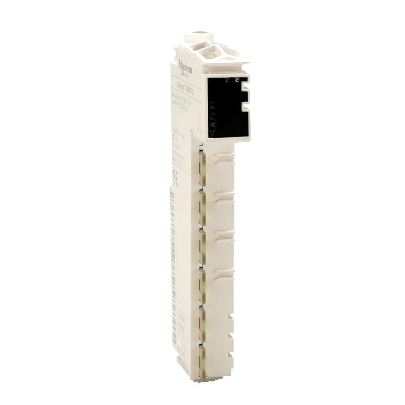
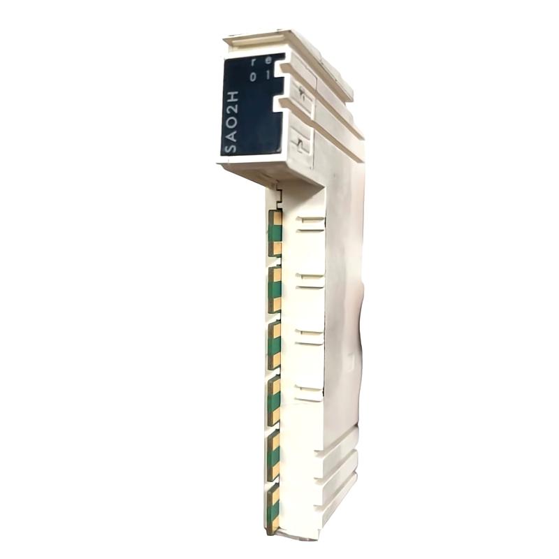
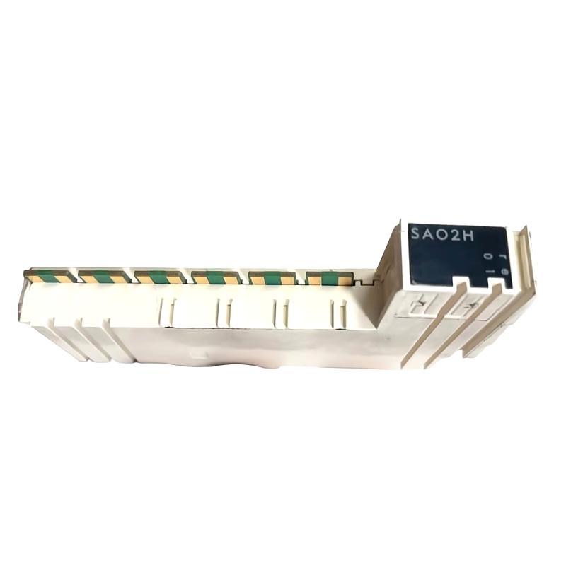
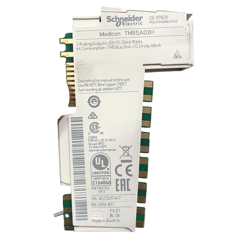
- Schneider
- TM5SAO2H
- Analog Output Module
- France
- 99 × 12.5 × 75 mm
- 0.025 kg
- Xiamen, China
- New & In Stock
- T/T, PayPal, Western Union
- 1 Year
- 1-3 Working Days
- DHL, UPS, TNT, FedEx and EMS.
- 24-Hour Service
- COO
- 3
Our advantage

Global Logistics
We have a 10-year logistics and express cooperation agreement, so our products can be shipped to any place in the world.

Brand new and original
Our products are imported in bulk from the place of origin. Because of the cooperative relationship, our products are all original and 100% new.

24-hour service
We provide 7*24 hours service to our customers. We will be there whenever you need us.

Price advantage
All our products are priced very favorably because we have our own warehouse and supply.
| Company Information | |||
| [email protected] | |||
| Mobile | +8615980777398 | ||
| +8615980777398 | |||
| 15980777398 |
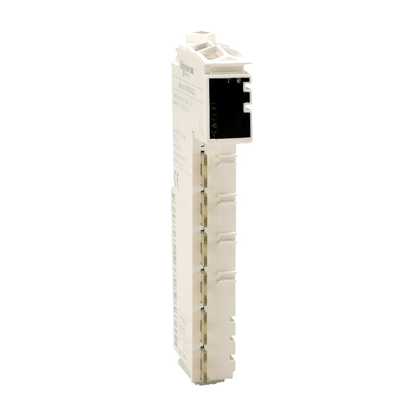
1. Product Overview
The Schneider TM5SAO2H Analog Output Module is an industrial automation component designed to provide analog output functionality within a compatible modular control system. Analog output modules allow a programmable logic controller (PLC) to send control signals to field devices, enabling automated adjustment of process variables and equipment operating conditions.
In industrial control applications, analog output signals are commonly used to regulate variable-speed drives, control valves, proportional actuators, and other devices that require continuously adjustable commands. By connecting the controller’s application logic with suitable field equipment, an analog output module helps implement closed-loop control, process regulation, and automated machine operation.
The TM5SAO2H belongs to Schneider Electric’s TM5 modular I/O product family. Its compact design makes it suitable for control panels and machine automation installations where efficient use of cabinet space is important. Before selecting or installing this module, engineers should verify the exact output signal types, channel configuration, electrical characteristics, and supported controller combinations for the specific hardware version.
The supplied dimensions are 99 × 12.5 × 75 mm, and the listed weight is 0.025 kg. These physical specifications can assist with inventory management, equipment identification, and preliminary cabinet-layout planning.
2. Technical Specifications
| Parameter | Specification |
|---|---|
| Brand | Schneider Electric |
| Model | TM5SAO2H |
| Product Type | Analog Output Module |
| Product Family | TM5 Modular I/O |
| Dimensions | 99 × 12.5 × 75 mm |
| Weight | 0.025 kg |
| Primary Function | Analog control signal output |
| Typical Application | PLC-based process and machine control |
| Installation | Compatible TM5 modular I/O assembly |
| System Integration | Subject to controller and hardware configuration compatibility |
Important specification note: The exact number of output channels, supported voltage or current ranges, output resolution, accuracy, load limits, isolation characteristics, and wiring requirements should be verified against the technical documentation for the specific TM5SAO2H version. These values should not be assumed from the model number alone.
3. Function and Working Principle
An analog output module converts controller commands into electrical output signals that compatible field devices can use to adjust equipment operation.
Unlike a digital output, which generally represents an ON or OFF state, an analog output can represent a range of commanded values. This capability allows a controller to adjust a process gradually rather than relying only on discrete switching.
3.1 Generating Analog Control Signals
The PLC executes its control program and calculates a desired output value based on operator commands, sensor feedback, operating conditions, or programmed sequences. The analog output module receives the configured output data and produces the corresponding electrical signal within its supported range.
The connected field device interprets this signal according to its own design and configuration.
For example, a controller may calculate a demand value for a compatible drive or valve actuator. The output module provides the control signal required by that device, provided the signal type and electrical specifications match.
3.2 Supporting Continuous Process Adjustment
Analog output functionality is useful when machinery needs more than simple start-and-stop control. It can support adjustable speed, position, flow, pressure, or other operating targets when used with suitable actuators and control equipment.
The actual controlled variable depends on the complete system. The output module provides the command interface; the connected device and the wider control loop determine the resulting physical response.
3.3 Integration with PLC Logic
The module operates as part of a larger automation architecture. The PLC application program determines the required output value, while the I/O configuration defines how that value is associated with the installed hardware.
Incorrect output mapping, scaling, or signal selection may cause the connected device to respond incorrectly. Therefore, the hardware configuration and application program should be checked together during commissioning.
3.4 Output Scaling and Engineering Units
A controller may calculate a command in engineering units such as percentage, speed, or pressure demand. That value must be mapped to the output representation supported by the module and connected equipment.
Correct scaling ensures that the commanded value corresponds to the intended electrical signal. Engineers should document the relationship between the controller’s raw output data, the configured signal range, and the field device’s expected input.
4. Role in Industrial Automation Systems
The Schneider TM5SAO2H Analog Output Module can serve as the command interface between a compatible PLC and analog-controlled field equipment. Its practical role depends on the control system architecture and the electrical requirements of the application.
4.1 Variable-Speed Drive Control
Many drive systems accept an analog reference signal for speed or another adjustable operating command. A compatible analog output interface can allow a PLC to provide that reference according to process demand.
Before connecting a drive, verify the drive’s input type, permissible signal range, reference configuration, grounding requirements, and operating mode.
4.2 Valve and Actuator Regulation
Industrial process systems frequently use modulating valves and actuators to adjust flow, pressure, temperature, or level. An analog output module can provide the command signal when the actuator supports the module’s verified output type.
The valve or actuator must be configured to interpret the signal correctly. Mechanical limits, fail-safe behavior, and process protection should be addressed separately in the overall system design.
4.3 Closed-Loop Process Control
In a closed-loop system, sensors measure the actual process condition and return feedback to the controller. The PLC compares this measurement with a target value and calculates a corrective command.
The analog output module sends that command to the relevant field device. This arrangement can help maintain stable operating conditions when the sensor, controller logic, actuator, and output interface are properly configured.
4.4 Automated Equipment Adjustment
Manufacturing machinery may require continuously adjustable commands for positioning systems, material handling, dosing, heating, or other operations. Analog outputs can support these functions where the connected equipment is designed for analog control.
Application engineers should confirm that an analog output is the appropriate interface; some devices instead require digital communication, pulse signals, or dedicated motion-control hardware.
5. Industrial Applications
5.1 Manufacturing and Assembly Equipment
Automated production lines often require adjustable commands for drives, actuators, and process equipment. A compatible analog output module can provide a control interface for these devices within the PLC architecture.
5.2 Pump and Fan Control
Pump and fan systems may use adjustable speed references to meet changing flow, pressure, or ventilation requirements. When the connected drive supports the configured analog input, the controller can use an analog output command to request a suitable operating level.
The module should not be assumed to provide drive protection or independent motor safety functions.
5.3 Process Control Systems
Industrial processes may require continuous adjustment of flow, pressure, temperature, or liquid level. Analog output signals can be used to command compatible control valves, actuators, and other regulating equipment.
The control system must account for sensor feedback, actuator response, process dynamics, and operating limits.
5.4 Packaging and Material Handling
Packaging machinery and material-handling equipment can require adjustable speed or process settings. An analog output interface may be appropriate where the controlled device accepts a supported analog command.
The application should be evaluated to determine whether analog control provides sufficient precision and response time.
5.5 Building and Utility Equipment
Some utility and facility-control applications use analog commands to regulate ventilation, pumping, or other equipment. Suitability depends on the required signal type, electrical environment, controller compatibility, and applicable equipment standards.
6. Installation and System Integration
Correct installation is essential for dependable output control. The following procedure is a general engineering checklist and does not replace the manufacturer’s instructions for the exact module.
6.1 Confirm Model and Controller Compatibility
Verify the complete model number and ensure that the module is supported by the intended TM5 system configuration. Check the required mounting, base, bus, and accessory components, as well as the applicable controller and engineering-software versions.
Do not assume that modules with similar dimensions or descriptions are interchangeable.
6.2 Isolate Power Before Installation
Before installing, removing, or rewiring the module, isolate the relevant power sources and follow the facility’s lockout/tagout procedures. Confirm that the system is in a safe state before touching electrical connections.
Follow the specified grounding, power distribution, and handling requirements to avoid damage to electronic components.
6.3 Verify the Field Device Input
Identify the electrical input requirements of the connected drive, valve positioner, actuator, or other field device. Confirm that the module’s supported output type and range match the receiving device.
Check polarity, common terminals, shielding, grounding, and load requirements according to the relevant product documentation.
6.4 Install the Module
Mount and secure the module according to the TM5 system assembly instructions. Confirm that the module is correctly seated and that the relevant connectors are installed in their designated positions.
Inspect the surrounding wiring and ensure that maintenance access and environmental requirements are satisfied.
6.5 Configure Hardware and Output Parameters
Configure the module in the applicable PLC engineering environment. Confirm that the controller recognizes the installed hardware and that the output channels are assigned correctly.
Set the appropriate output type, scaling, engineering units, and application limits where supported. Ensure that the controller’s raw output values correspond to the expected electrical signal.
6.6 Commission the Output
Before enabling the connected machinery, verify the wiring and configuration. Where practical, test the output using an appropriate measurement instrument and approved commissioning procedure.
Check that the electrical signal changes as expected when the controller command changes. Then verify the field device’s response under controlled conditions, including minimum and maximum permitted commands.
Confirm the system’s startup state, behavior during controller faults, and response to loss of communication or power. These behaviors depend on the complete control system and should be validated as part of commissioning.
7. Troubleshooting Common Problems
Analog output faults can originate from the module, PLC configuration, field wiring, connected equipment, power supply, or application logic. Diagnose the complete control loop before replacing hardware.
7.1 No Output Signal
Possible causes:
- Incorrect module installation.
- Output channel not configured or mapped correctly.
- PLC program not writing the intended value.
- Wiring fault or disconnected field device.
- Incompatible output and input signal types.
- A fault in the connected device or module.
Recommended checks:
- Review controller and I/O diagnostic messages.
- Confirm that the PLC program is generating the expected command.
- Check hardware configuration and output-channel mapping.
- Inspect field wiring after isolating power where required.
- Measure the output using an appropriate instrument and approved procedure.
- Confirm that the receiving device is powered and configured correctly.
7.2 Incorrect Output Value
An output value that differs from the expected command may be caused by incorrect scaling, an incorrect signal-range selection, an application-programming error, or a mismatch between the module and the receiving device.
Check the relationship between the PLC command value and the intended electrical output. Confirm that the field device interprets the selected signal range correctly.
7.3 Output Signal Fluctuation
Unstable output behavior may result from rapidly changing PLC commands, control-loop tuning, electrical interference, grounding problems, loose connections, or issues in the connected equipment.
Review the controller program and trend data first. Inspect wiring practices and shielding, and verify that the control loop is configured for the response characteristics of the process.
7.4 Connected Device Does Not Respond
A valid output signal does not guarantee that the field device will operate. The receiving equipment may have its own enable conditions, local/remote selection, interlocks, configuration settings, or fault status.
Verify the electrical signal at the receiving device and review its diagnostic information. Confirm that the device is configured to accept the intended command and that independent permissive conditions are satisfied.
7.5 Controller Reports an I/O Error
An I/O error may indicate a configuration mismatch, incomplete hardware assembly, a communication or bus problem, or a hardware fault.
Check the module identification, controller configuration, system connections, and diagnostic messages. Follow the manufacturer’s fault-isolation procedure before deciding that the module must be replaced.
8. Compatible System Components
A typical analog output application may include the following components. Exact compatibility must be verified for the intended installation.
| Component | Purpose |
|---|---|
| Compatible Schneider Electric PLC or controller | Executes control logic and generates output commands |
| TM5 modular I/O system components | Provide the required mechanical and electrical system interface |
| Compatible variable-speed drive | Receives an analog reference where supported |
| Modulating valve or actuator | Converts a compatible command into physical adjustment |
| Field wiring and terminal connections | Carry output signals to receiving devices |
| Suitable power supply | Powers the relevant control and field equipment |
| Engineering software | Supports hardware configuration, programming, and diagnostics |
| HMI or supervisory system | Allows operators to monitor process values and adjust permitted setpoints |
| Industrial communication infrastructure | Supports communication among controllers and supervisory equipment where required |
The final configuration should be checked against the hardware documentation and the electrical specifications of every connected device.
9. Replacement and Alternative Selection
Selecting a replacement for the Schneider TM5SAO2H requires more than matching the general description of an analog output module. A replacement must meet the control system’s electrical, mechanical, and software requirements.
| Selection Factor | Verification Requirement |
|---|---|
| Product family | Confirm compatibility with the existing TM5 architecture |
| Output signal type | Match the input requirements of the receiving device |
| Number of channels | Ensure sufficient outputs for the application |
| Output range | Confirm the supported voltage or current range |
| Resolution and accuracy | Meet the required control performance |
| Load requirements | Verify the electrical limits for the connected device |
| Wiring arrangement | Confirm terminals, connectors, polarity, and common connections |
| Controller support | Check hardware and software compatibility |
| Mechanical dimensions | Verify mounting and cabinet-space requirements |
| Fault behavior | Confirm the required response during startup, power loss, and controller faults |
If the original module is unavailable, select a substitute only after verifying its specifications and suitability for the existing hardware configuration. Similar dimensions or a similar product name do not establish functional equivalence.
10. Key Advantages
Compact design: The listed dimensions of 99 × 12.5 × 75 mm support space-conscious control cabinet planning.
Low listed weight: The specified weight of 0.025 kg can simplify inventory handling and physical installation planning.
Analog command interface: The module’s intended output function supports adjustable control commands for compatible industrial devices.
Modular system integration: As a TM5-family component, it can be evaluated for use in the corresponding modular I/O architecture, subject to verified compatibility.
Flexible control applications: Analog output functionality can support drive references, actuator commands, and other process-control tasks when the receiving equipment supports the required signal.
Maintainability: Correct hardware identification, documented output mapping, and clear wiring records help streamline troubleshooting and replacement.
11. Technical FAQs
Q1: What is the Schneider TM5SAO2H Analog Output Module used for?
It is identified as an analog output module for industrial automation. Its intended role is to provide control signals from a compatible controller to field devices that accept supported analog inputs.
Q2: What are the dimensions and weight of the TM5SAO2H?
The supplied specifications list dimensions of 99 × 12.5 × 75 mm and a weight of 0.025 kg.
Q3: Can it control a variable-speed drive?
It may be suitable when the drive accepts an analog reference that matches the module’s verified output characteristics. Confirm the signal type, range, wiring, and drive configuration before connecting the equipment.
Q4: Can it be connected to any Schneider Electric PLC?
No. Compatibility depends on the controller, TM5 hardware configuration, engineering-software support, and the overall system architecture. Confirm the supported configuration before purchase or installation.
Q5: Why does the connected actuator not respond?
Possible causes include incorrect wiring, incompatible signal types, incorrect scaling, an unconfigured output channel, a disabled actuator, or active equipment interlocks. Check both the output signal and the receiving device’s status.
Q6: How should the analog output be tested?
Follow the applicable manufacturer procedure. Verify the controller command, channel configuration, wiring, and electrical signal with suitable test equipment. Test the field device under controlled conditions and observe all safety requirements.
Q7: What information is needed to select a replacement?
The complete model number, supported output range, channel count, accuracy, load requirements, wiring arrangement, controller compatibility, and fault behavior should all be considered. Confirm these parameters using the applicable technical documentation.
12. Conclusion
The Schneider TM5SAO2H Analog Output Module is an industrial automation component intended to provide analog command signals within a compatible TM5 modular I/O system. It can support applications involving adjustable drives, modulating actuators, and other field devices that accept the module’s supported output signals.
Reliable performance depends on correct hardware selection, electrical compatibility, output scaling, controller programming, and commissioning. Engineers should verify all model-specific parameters before connecting equipment or planning a replacement.
For maintenance teams, system integrators, and industrial spare-parts buyers, confirming the complete model number and technical specifications is essential to ensure the module matches the requirements of the existing automation system.