

ProductPRODUCT
Featured products
Contact Us
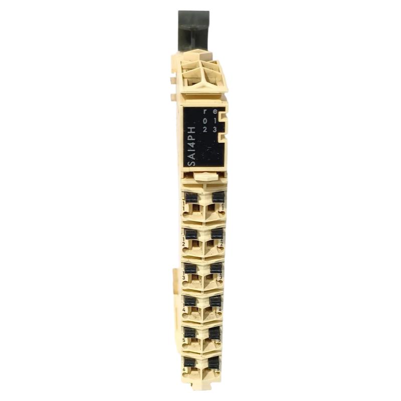
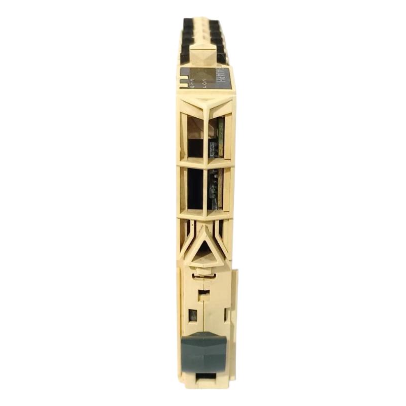
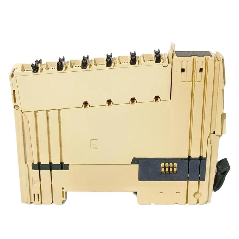
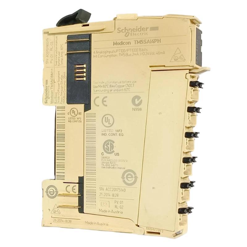
- Schneider
- TM5SAI4PH
- Analog Input Module
- France
- 99 × 12.5 × 75 mm
- 0.025 kg
- Xiamen, China
- New & In Stock
- T/T, PayPal, Western Union
- 1 Year
- 1-3 Working Days
- DHL, UPS, TNT, FedEx and EMS.
- 24-Hour Service
- COO
- 5
Our advantage

Global Logistics
We have a 10-year logistics and express cooperation agreement, so our products can be shipped to any place in the world.

Brand new and original
Our products are imported in bulk from the place of origin. Because of the cooperative relationship, our products are all original and 100% new.

24-hour service
We provide 7*24 hours service to our customers. We will be there whenever you need us.

Price advantage
All our products are priced very favorably because we have our own warehouse and supply.
| Company Information | |||
| [email protected] | |||
| Mobile | +8615980777398 | ||
| +8615980777398 | |||
| 15980777398 |
1. Product Overview
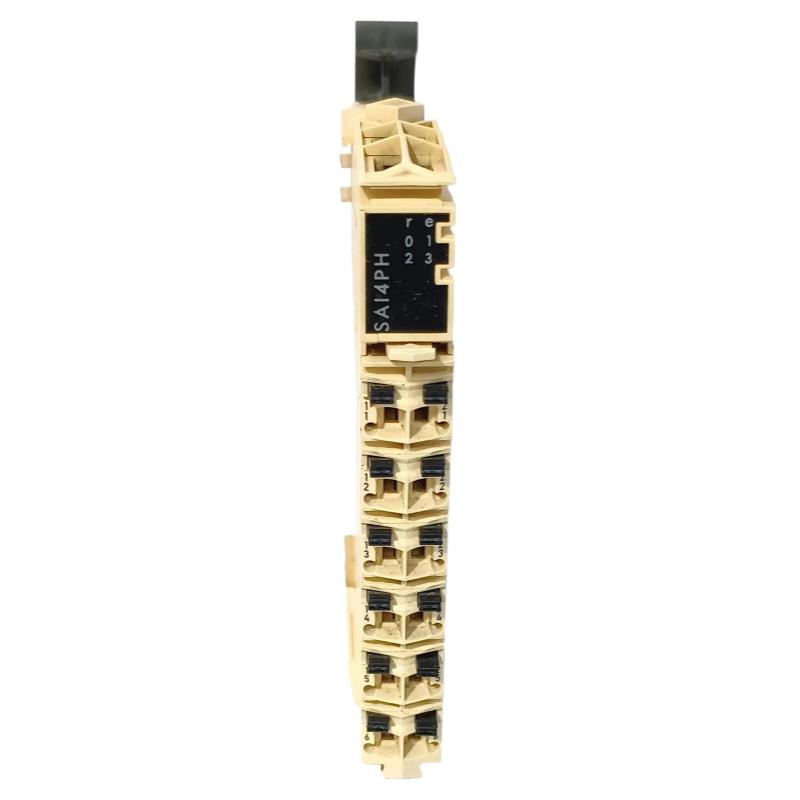
The Schneider TM5SAI4PH Analog Input Module is an industrial automation component designed for analog signal acquisition in compatible control systems. Analog input modules allow a controller to receive measurement signals from field instruments and use the collected data for monitoring, process regulation, alarms, and automated control operations.
In industrial applications, analog signals are commonly generated by pressure transmitters, temperature measurement devices, flow instruments, and other process sensors. A suitable analog input module provides the interface between these field signals and the controller, enabling measured values to be incorporated into the automation program.
The Schneider TM5SAI4PH has specified dimensions of 99 × 12.5 × 75 mm and a listed weight of 0.025 kg. Its compact physical design is useful when evaluating control cabinet space, mounting arrangements, and replacement requirements.
Before integrating this module into an existing installation, engineers should confirm the supported input signal types, channel configuration, electrical characteristics, controller compatibility, and applicable configuration requirements. These details are important for reliable measurement and accurate process control.
2. Technical Specifications
| Parameter | Specification |
|---|---|
| Brand | Schneider Electric |
| Model | TM5SAI4PH |
| Product Type | Analog Input Module |
| Dimensions | 99 × 12.5 × 75 mm |
| Weight | 0.025 kg |
| Product Category | Industrial automation I/O |
| Primary Function | Analog signal acquisition |
| Typical Signal Sources | Compatible industrial transmitters and sensors |
| System Role | Interface between field measurements and a controller |
| Mounting and Installation | According to the applicable TM5 system configuration |
| Input Signal Types | Verify against the exact model documentation |
| Number of Channels | Confirm against the official module specifications |
| Input Resolution | Verify against the exact model documentation |
| Electrical Isolation | Confirm the specified isolation arrangement |
| Controller Compatibility | Verify the supported controller and I/O system |
| Configuration Method | Follow the applicable hardware and software documentation |
The dimensions and weight above are based on the supplied product information. Specific electrical parameters, supported signal ranges, channel count, and resolution should be confirmed before selecting the module for a particular application.
3. Function and Working Principle
3.1 Analog Signal Acquisition
Industrial field instruments often produce electrical signals that represent measured process variables. These signals may correspond to pressure, temperature, flow, level, or another physical quantity.
An analog input module receives supported signals and converts them into digital values that can be processed by the connected controller. The controller can then use these values in its control logic, monitoring functions, alarms, and communication with supervisory systems.
The accuracy of the final measurement depends on the field instrument, wiring, input configuration, signal characteristics, module performance, and controller scaling.
3.2 Integration with Industrial Controllers
An analog input module forms part of a wider automation architecture. It receives measurement signals from the field and makes the corresponding values available to compatible control equipment.
Depending on the application, the controller may use these values to regulate a process, display measurements on an operator interface, activate an alarm, or transmit data to a supervisory control system.
Correct hardware configuration and software mapping are necessary to ensure that each input value is assigned to the intended variable in the control program.
3.3 Signal Scaling and Engineering Units
The electrical signal received by an analog input module must be interpreted correctly by the control program. For example, a field transmitter may represent a process measurement across a defined electrical range.
The controller program can scale the acquired input value into engineering units, such as degrees Celsius, bar, litres per minute, or percentage of range. The scaling formula must match the field instrument’s configured output range and the module’s actual input characteristics.
Incorrect scaling can cause displayed values to differ from the actual process condition, even when the module is functioning correctly.
3.4 Continuous Process Monitoring
When correctly configured, analog input modules allow automation systems to monitor changing process conditions. The controller can evaluate incoming measurements repeatedly and respond according to the programmed control strategy.
This capability supports process regulation, equipment supervision, trend recording, and alarm generation in industrial facilities.
4. Role in Industrial Automation Systems
Process Measurement
Analog input modules provide a way to incorporate field measurements into the control system. Depending on the supported input configuration, compatible instruments can supply data for monitoring important operating parameters.
Closed-Loop Control
In a closed-loop control system, an analog measurement may be compared with a target value. The controller uses the difference between the measured value and the target to calculate an appropriate control response.
For example, a temperature measurement may be used by a control program to adjust a heating or cooling process. The module provides the measurement input, while the control algorithm and output hardware perform the associated control functions.
Alarm and Event Handling
The controller can evaluate incoming values against configured limits and generate alarms when a process variable moves outside its acceptable range. Appropriate limits, filtering, and response logic must be established according to the application requirements.
Supervisory System Integration
Measurements acquired by the module may be used by compatible supervisory systems through the controller’s communication architecture. This can support operator displays, historical trends, production reporting, and remote process supervision.
Industrial I/O Expansion
In modular automation architectures, suitable I/O modules allow system designers to organize field signals according to process requirements. Before adding or replacing a module, verify the supported hardware configuration, power requirements, and controller limitations.
5. Industrial Applications
5.1 Manufacturing Automation
Manufacturing systems often require continuous monitoring of pressure, temperature, flow, and other process variables. Compatible analog input modules allow these measurements to be incorporated into control logic and production monitoring.
5.2 Process Control
Chemical processing, water treatment, and other industrial processes use field instruments to measure operating conditions. Analog measurements can support process regulation, alarm generation, and supervisory monitoring.
The module must be configured for the actual signal type and range supplied by each connected instrument.
5.3 HVAC and Building Equipment
Industrial heating, ventilation, and cooling systems may use analog measurement signals from compatible temperature, pressure, or other transmitters. These measurements can help controllers regulate equipment operation and maintain required process conditions.
5.4 Water and Wastewater Treatment
Water treatment systems use instrumentation to monitor process conditions at different stages. Where the instrument outputs match the module’s supported input characteristics, the acquired values can be used for control and operational monitoring.
5.5 Machine and Equipment Monitoring
Machines may use analog sensors to provide information about operating conditions. The controller can process the acquired values to support sequencing, interlocks, alarms, and maintenance-related monitoring functions.
5.6 Industrial Energy Management
Energy-related applications may monitor variables such as pressure, temperature, or flow. Analog measurements can contribute to operational analysis when the sensors, module, and controller are correctly configured.
6. Installation and System Integration
Correct installation and configuration are essential for reliable signal acquisition. The following procedure provides a general checklist. The exact Schneider Electric hardware documentation should take precedence for module-specific mounting and wiring requirements.
Step 1: Verify the Model
Confirm that the product label identifies the module as TM5SAI4PH. Compare the model number with the system bill of materials and controller configuration.
Do not assume that modules with similar model numbers have the same input types, channel assignments, or electrical characteristics.
Step 2: Inspect the Module
Before installation, inspect the module housing and electrical connection areas for cracks, deformation, contamination, corrosion, or other visible damage.
Check that the required mounting accessories and compatible system components are available. Do not install a damaged module in a live control system.
Step 3: Confirm System Compatibility
Verify that the intended controller and I/O architecture support the TM5SAI4PH. Review the hardware configuration, power requirements, module placement restrictions, and any required expansion components.
Compatibility should be confirmed before wiring or applying power.
Step 4: Install the Module
Mount the module according to the applicable hardware instructions. Ensure that it is properly secured and that the installation provides the required spacing, environmental protection, and access for maintenance.
The supplied dimensions of 99 × 12.5 × 75 mm can assist with space planning, but the complete assembly clearance should also be considered.
Step 5: Connect Field Signals
Identify each field instrument and confirm its output type, signal range, wiring arrangement, and polarity where applicable. Connect the field wiring to the designated terminals according to the module documentation.
Use suitable cable types and follow the site’s grounding, shielding, and electrical noise-control practices. Do not assume a particular terminal assignment without checking the exact wiring diagram.
Step 6: Configure the Hardware
Use the applicable engineering software to configure the module and its supported input channels. Confirm that the hardware configuration matches the installed physical equipment.
Incorrect module selection or channel configuration can prevent measurements from being acquired correctly.
Step 7: Configure Scaling and Logic
Map the acquired values to the correct program variables. Configure engineering-unit scaling, filtering, alarm thresholds, and control logic according to the instrument specifications and process requirements.
Test the conversion from electrical input to displayed engineering value using an approved commissioning method.
Step 8: Commission the System
After checking the wiring and configuration, verify that the controller recognizes the module and that the acquired values are plausible.
Where appropriate, compare readings with a calibrated reference instrument or an approved signal source. Check for unexpected fluctuations, out-of-range values, incorrect channel mapping, or scaling errors before placing the system into normal operation.
Step 9: Document the Installation
Record the module model, mounting position, channel assignments, connected instruments, signal ranges, scaling parameters, and commissioning results.
Accurate documentation helps future maintenance personnel troubleshoot faults and replace components without introducing configuration errors.
7. Troubleshooting Common Problems
Problem 1: No Analog Input Value
Possible causes:
- Incorrect field wiring.
- Missing signal from the connected instrument.
- Incorrect module configuration.
- Incompatible input signal type.
- Module or system power problem.
- Fault in the field instrument or input circuit.
Recommended checks:
Verify the field instrument’s output and check the wiring against the correct terminal diagram. Confirm that the module is recognized by the controller and that the channel is configured correctly. If the instrument signal is present but the input value remains unavailable, investigate the module configuration and hardware status.
Problem 2: Incorrect Measurement Values
Possible causes:
- Incorrect engineering-unit scaling.
- Mismatch between transmitter output and module input configuration.
- Incorrect channel mapping.
- Wiring errors.
- Incorrect instrument calibration.
- Signal outside the supported range.
Recommended checks:
Compare the transmitter’s configured output range with the module’s supported input range. Review the scaling calculation and channel mapping in the control program. Where possible, compare the displayed value with a calibrated reference.
Problem 3: Fluctuating Analog Readings
Possible causes:
- Electrical interference.
- Poor wiring connections.
- Inadequate shielding or grounding.
- Unstable field instrument output.
- Incorrect filtering or sampling configuration.
- Actual process variation.
Recommended checks:
Inspect wiring and connections, then review the grounding and shielding arrangement. Compare the module value with the field instrument’s output or an independent measurement. Determine whether the fluctuations originate in the process, instrument, wiring, or input configuration before adjusting filtering.
Problem 4: Controller Does Not Recognize the Module
Possible causes:
- Unsupported hardware configuration.
- Incorrect module selection in the engineering software.
- Improper installation.
- Power or system connection problem.
- Damaged module or associated hardware.
Recommended checks:
Verify the exact module model and confirm that the controller supports the installed configuration. Inspect the mounting and system connections, check diagnostic information, and follow the approved startup procedure.
Problem 5: Measurements Are Outside the Expected Range
Possible causes:
- Incorrect sensor range.
- Wrong input configuration.
- Faulty transmitter.
- Wiring or polarity error.
- Incorrect scaling parameters.
- Signal outside the module’s supported limits.
Recommended checks:
Verify the field instrument’s output specification and compare it with the module configuration. Check the wiring, scaling parameters, and controller diagnostics. Do not simply increase alarm limits to hide an unexpected measurement.
Problem 6: Intermittent Input Faults
Possible causes:
- Loose terminals.
- Damaged field cable.
- Intermittent instrument output.
- Electrical noise.
- Unstable power or system connections.
- Hardware malfunction.
Recommended checks:
Inspect the complete signal path and review controller diagnostics for recurring fault patterns. Check the instrument and wiring under the approved maintenance procedure. Replace a module only after other likely causes have been evaluated.
Safety note: Follow site electrical isolation procedures before handling module terminals or changing field wiring. Where the module is used in a process involving hazardous equipment, follow the applicable safety and commissioning requirements.
8. Compatible System Components
The TM5SAI4PH must be evaluated as part of a complete automation system. The following table identifies typical component categories and does not confirm compatibility with any specific part number.
| Component Category | Function | Verification Requirement |
|---|---|---|
| Compatible Controller | Executes control logic and processes input values | Confirm controller and firmware support |
| TM5 I/O System Components | Provide the required modular hardware arrangement | Verify system configuration and permitted combinations |
| Field Transmitters | Supply analog process measurements | Output type and range must match the module |
| Temperature or Pressure Instruments | Measure process variables | Verify signal compatibility and calibration |
| Field Wiring and Terminals | Carry signals to the module | Follow the correct wiring and grounding requirements |
| Engineering Software | Configures hardware and application logic | Confirm support for the installed controller and module |
| HMI or Supervisory System | Displays and records process values | Configure the appropriate controller communication and variable mapping |
| Reference Signal Source | Supports commissioning and input testing | Use a suitable calibrated device and approved test method |
Always confirm compatibility using the actual controller configuration and module documentation. A common manufacturer or product family does not automatically guarantee that two components can be used together.
9. Recommended Replacement Selection
If the TM5SAI4PH needs to be replaced or an alternative is being considered, selection should be based on documented electrical and system compatibility.
| Replacement Option | When to Consider It | Important Checks |
|---|---|---|
| Schneider TM5SAI4PH | Preferred when the existing system requires this exact model | Full part number, condition, and system configuration |
| Compatible Schneider Analog Input Module | When the existing system supports an approved alternative | Signal types, channel count, input range, and configuration |
| Compatible Modular I/O Solution | When expanding or redesigning the automation system | Controller support, mounting, power, and software configuration |
| Alternative Analog Acquisition System | When a broader system upgrade is planned | Signal compatibility, accuracy requirements, communications, and commissioning |
A different analog input module should not be treated as a direct replacement based on appearance or dimensions alone. Verify signal characteristics, channel configuration, controller support, and wiring requirements before ordering.
10. Key Advantages of Analog Input Modules
Integration of Field Measurements
Analog input modules provide a structured way to bring compatible instrument signals into an automation system, enabling measured process values to be used by controller logic.
Support for Process Monitoring
Acquired values can be displayed, recorded, and evaluated to support process supervision and maintenance activities.
Use in Automated Control
When paired with suitable controllers and output hardware, analog input data can contribute to feedback control and automatic adjustment of process variables.
Modular System Design
Modular I/O architectures allow engineers to organize field signal acquisition according to application requirements, subject to the supported system configuration.
Compact Physical Design
The supplied dimensions of 99 × 12.5 × 75 mm and weight of 0.025 kg provide useful information for cabinet planning, handling, and spare-parts identification.
11. Technical FAQs
Q1: What is the Schneider TM5SAI4PH?
The TM5SAI4PH is identified as an analog input module for industrial automation applications. Its exact signal capabilities and system requirements should be verified against the applicable product documentation.
Q2: What are the dimensions of the TM5SAI4PH?
The supplied dimensions are 99 × 12.5 × 75 mm.
Q3: How much does the module weigh?
The listed weight is 0.025 kg.
Q4: What is the primary function of an analog input module?
It receives supported analog signals from field instruments and makes the corresponding measurement values available to a compatible controller.
Q5: Which field instruments can be connected?
Compatible instruments may include transmitters or sensors that produce signal types supported by the module. Confirm the input range, wiring, and electrical characteristics before connecting an instrument.
Q6: Can the module connect to any PLC?
No. Controller compatibility depends on the module’s hardware architecture and the supported I/O system. Verify the exact controller and configuration before installation.
Q7: Why are analog readings incorrect?
Common causes include incorrect scaling, a mismatched signal range, wiring errors, incorrect channel mapping, instrument calibration problems, or electrical interference.
Q8: What should be checked before replacing the module?
Confirm the complete model number, controller compatibility, supported input characteristics, dimensions, terminal arrangement, and existing configuration.
Q9: How can reliable analog measurements be maintained?
Use correct wiring and grounding practices, verify signal scaling, inspect field connections, and periodically compare important measurements with suitable reference instruments.
Q10: What information should be confirmed before purchasing?
Confirm the model number, required quantity, physical condition, input characteristics, channel configuration, controller compatibility, and any required accessories.
12. Conclusion
The Schneider TM5SAI4PH Analog Input Module is an industrial automation component intended to support analog signal acquisition in a compatible control system. Its specified dimensions of 99 × 12.5 × 75 mm and listed weight of 0.025 kg provide useful physical information for installation planning, component identification, and spare-parts purchasing.
Successful integration depends on selecting compatible field instruments, configuring the hardware correctly, applying accurate engineering-unit scaling, and verifying signal quality during commissioning. Before installing or replacing the module, confirm its exact electrical specifications and compatibility with the intended controller and I/O architecture.
For automation engineers, maintenance teams, and industrial spare-parts purchasers, careful verification helps reduce configuration errors and supports reliable process monitoring and control.