

ProductPRODUCT
Featured products

Contact Us
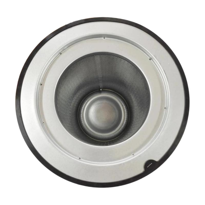
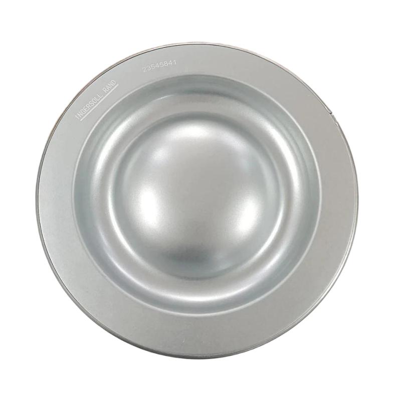
- Ingersoll Rand
- 47555211001 23545841
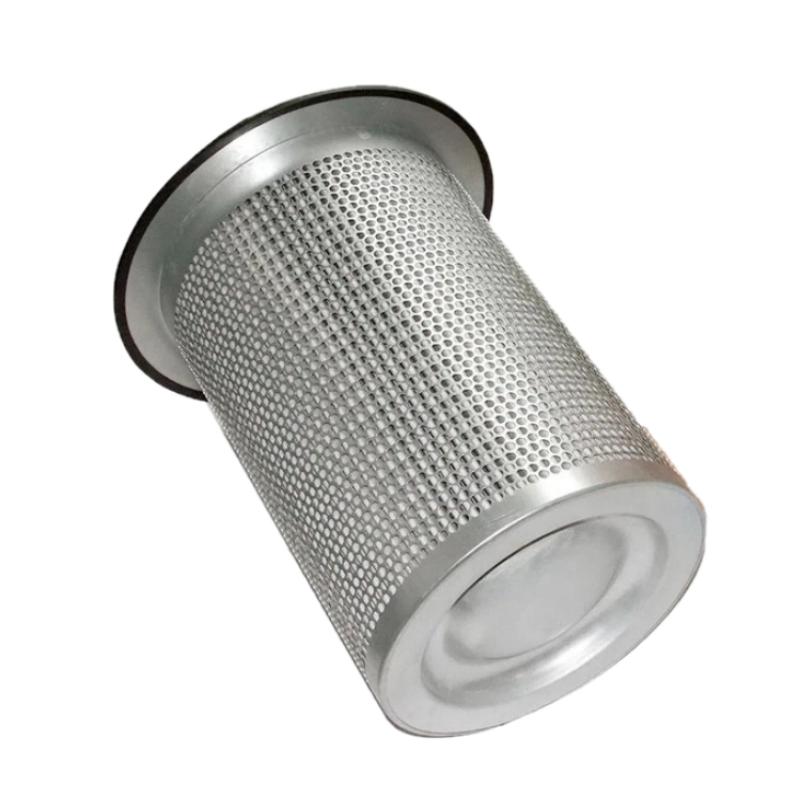
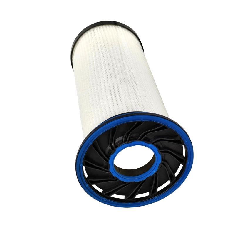
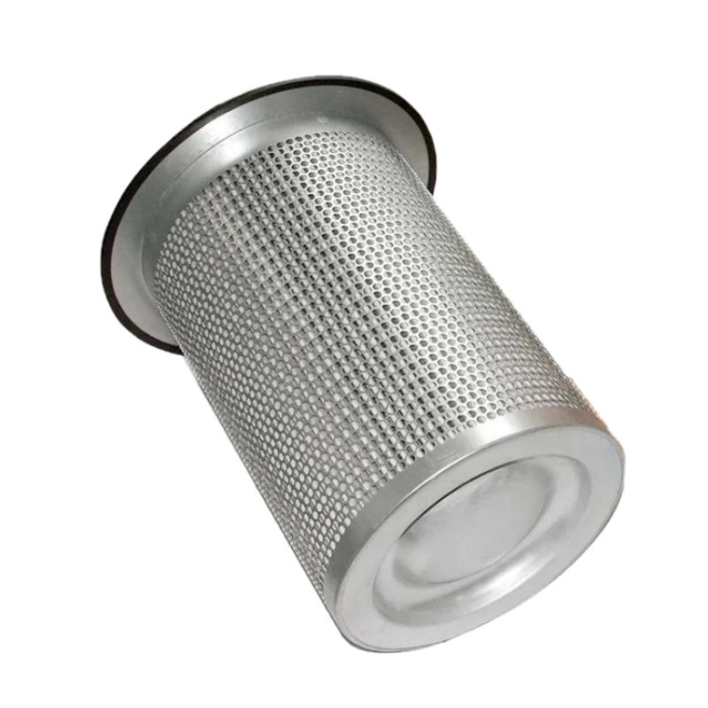
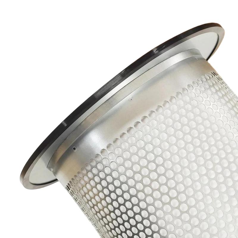
- Air-oil separator
- USA
- 375 mm
- 7.5 kg
- Xiamen, China
- New & In Stock
- T/T, PayPal, Western Union
- 1 Year
- 1-3 Working Days
- DHL, UPS, TNT, FedEx and EMS.
- 24-Hour Service
- COO
- 6
Our advantage

Global Logistics
We have a 10-year logistics and express cooperation agreement, so our products can be shipped to any place in the world.

Brand new and original
Our products are imported in bulk from the place of origin. Because of the cooperative relationship, our products are all original and 100% new.

24-hour service
We provide 7*24 hours service to our customers. We will be there whenever you need us.

Price advantage
All our products are priced very favorably because we have our own warehouse and supply.
| Company Information | |||
| [email protected] | |||
| Mobile | +8615980777398 | ||
| +8615980777398 | |||
| 15980777398 |
Product Overview
The Ingersoll Rand 47555211001 Air-Oil Separator, associated with part number 23545841, is an industrial compressor filtration component designed for applications where compressed air must be separated from lubricating oil. Air-oil separation is an important part of many oil-injected rotary screw compressor systems because it helps reduce oil carryover in the compressed-air stream while allowing recovered lubricant to return to the compressor’s lubrication circuit.
During compression, lubricating oil may be introduced into the compression chamber to assist with sealing, cooling, and lubrication. The resulting air-oil mixture must pass through a separation stage before the compressed air is delivered to downstream equipment. An air-oil separator helps remove entrained oil droplets from this mixture, supporting compressor performance and helping control lubricant consumption.
The Ingersoll Rand 47555211001 / 23545841 is identified by the supplied product information as an air-oil separator with a diameter of 375 mm and a weight of 7.5 kg. These physical specifications are useful for equipment identification, replacement planning, warehouse inventory, and maintenance preparation.
Correct selection is essential because separator elements can differ in dimensions, sealing arrangements, filtration characteristics, operating-pressure limits, and compatibility with specific compressor models. Before installation, verify the complete part number and confirm that the separator matches the compressor’s requirements.
Technical Specifications
| Parameter | Specification |
|---|---|
| Manufacturer | Ingersoll Rand |
| Part Number | 47555211001 |
| Associated Part Number | 23545841 |
| Product Type | Air-Oil Separator |
| Equipment Category | Industrial Air Compressor Filtration |
| Primary Function | Separation of entrained oil from compressed air |
| Diameter | 375 mm |
| Weight | 7.5 kg |
| Installation | Compatible compressor separator housing; verify the exact arrangement |
| Typical Application | Oil-injected industrial air compressor systems |
| Replacement Requirement | Confirm compressor model, part number, dimensions, and sealing configuration |
The specifications above reflect the supplied product identification and physical measurements. Filtration efficiency, operating pressure, temperature limits, differential-pressure limits, and service life should be confirmed for the exact separator and compressor application rather than assumed from the dimensions alone.
What Is an Air-Oil Separator?
An air-oil separator is a filtration component used in many oil-injected air compressors. Its purpose is to remove oil carried by the compressed-air stream after the compression process.
Oil is necessary in many rotary screw compressors because it helps cool the compression process, lubricate moving components, and improve sealing between the rotors. However, the compressed air leaving the compression chamber contains oil in suspended droplets or mist form. If this oil is not separated effectively, excessive carryover may reach the air outlet, downstream filters, dryers, piping, and pneumatic equipment.
The separator provides a dedicated stage for removing much of this entrained oil. The separated lubricant can then be collected and returned through the compressor’s oil-return arrangement, where the system design supports that function.
The Ingersoll Rand 47555211001 / 23545841 is intended for an appropriate compressor application, but the precise housing design and return arrangement must be confirmed for the equipment in which it will be installed.
Working Principle of an Air-Oil Separator
Air-oil separation typically involves a combination of flow management, droplet coalescence, and drainage. The precise internal construction depends on the separator design.
1. Air-Oil Mixture Enters the Separation Stage
During compression, oil mixes with air inside the compressor. The mixture is directed into the separator assembly, where the system’s flow path and separation components help reduce the amount of oil carried into the compressed-air outlet.
2. Oil Droplets Are Captured
Within a suitable separator medium, small oil droplets can collect on the internal fibers or other separation surfaces. As droplets accumulate, they combine into larger droplets through a process known as coalescence.
Larger droplets are easier to separate from the air stream and can drain toward the collection area.
3. Separated Oil Is Collected
The separated oil gathers within the separator housing or designated collection region. In compressor designs equipped with an oil-return system, the recovered lubricant is directed back to the appropriate part of the lubrication circuit.
The oil-return line, orifice, and associated fittings must remain clear and correctly installed to support the intended operation.
4. Compressed Air Continues to the Outlet
After passing through the separation stage, the compressed air continues through the compressor’s downstream flow path. The separator helps reduce oil carryover, but it should not be regarded as a substitute for other filtration or air-treatment equipment when the application requires additional air purification.
5. Differential Pressure Develops During Operation
As air flows through the separator, a pressure difference develops between its inlet and outlet. A suitable separator is designed to operate within specified limits.
Contamination, oil degradation products, incorrect installation, or a separator that is unsuitable for the application may cause excessive pressure drop. Differential pressure should therefore be evaluated according to the compressor manufacturer’s maintenance requirements.
Role in an Industrial Compressed-Air System
The air-oil separator is part of the compressor’s internal air and lubricant management system. Its condition can affect compressed-air quality, oil consumption, compressor energy use, and maintenance requirements.
A typical oil-injected compressor arrangement includes the following functional stages:
Air Intake → Compression Chamber → Air-Oil Separation → Compressed-Air Outlet → Downstream Air Treatment
A parallel lubricant path collects and returns separated oil to the compressor’s lubrication circuit. The actual layout depends on the compressor model.
The separator contributes to several operational objectives:
- Reducing oil carryover in the compressed-air stream
- Supporting lubricant recovery
- Helping maintain the intended compressor operating conditions
- Reducing oil contamination in downstream equipment
- Supporting efficient operation when the separator is correctly selected and maintained
- Helping maintenance personnel identify filtration-related problems through pressure and oil-consumption trends
Separator performance depends on the entire compressor system, including oil condition, operating temperature, flow rate, separator installation, and the condition of the oil-return circuit.
Industrial Applications
Manufacturing Facilities
Manufacturing plants use compressed air for pneumatic actuators, assembly equipment, material handling, and general production operations. Effective oil separation helps control lubricant carryover from oil-injected compressors.
Packaging Machinery
Packaging lines may use compressed air for pneumatic cylinders, product handling, positioning, and control functions. Excessive oil carryover can contribute to contamination and additional maintenance in applications where air cleanliness is important.
Automotive Production
Automotive facilities use compressed air for pneumatic tools, assembly equipment, fixtures, and general plant services. Air-oil separators support the compressor’s internal filtration process and help reduce lubricant transfer into the compressed-air system.
Food and Beverage Facilities
Food and beverage production often has specific compressed-air quality requirements. An air-oil separator can help reduce oil carryover from an oil-injected compressor, but it does not by itself guarantee compliance with application-specific air-purity requirements. Additional filtration, treatment, monitoring, and risk assessment may be necessary.
Pharmaceutical and Process Industries
Process plants may use compressed air for instrumentation, pneumatic controls, material handling, and other utility functions. Separator selection should be based on the compressor design and the required air quality at the point of use.
General Industrial Utilities
Workshops, maintenance facilities, and industrial utility rooms rely on compressed air for tools, cleaning equipment, and pneumatic systems. A correctly matched separator helps the compressor maintain its intended separation performance.
Installation and Replacement Guide
The Ingersoll Rand 47555211001 / 23545841 should be installed only after confirming that it is suitable for the specific compressor model and separator housing.
1. Confirm the Replacement Part
Before ordering or installing the separator, verify:
- Complete part number: 47555211001
- Associated part number: 23545841
- Separator diameter: 375 mm
- Overall physical fit and height
- Sealing arrangement and gasket design
- Compressor model and serial information
- Any relevant supersession or revision information
A matching diameter alone is not sufficient to establish compatibility. Two separators with the same outside diameter may have different heights, internal construction, connection arrangements, or filtration characteristics.
2. Shut Down and Isolate the Compressor
Before maintenance, stop the compressor and isolate it from its energy sources according to the applicable service procedure. Allow the equipment to cool and release internal pressure through the designated method.
Never loosen a pressurized separator housing. Residual pressure and hot oil can cause serious injury. Follow the compressor manufacturer’s lockout, depressurization, and personal-protection requirements.
3. Remove the Existing Separator
Open the designated service access according to the equipment instructions. Remove the old separator carefully, avoiding damage to the housing, sealing surfaces, oil-return connections, or nearby components.
Record the original installation arrangement where useful for reassembly. Inspect the removed element for unusual deformation, contamination, damaged seals, or signs of abnormal oil carryover.
4. Inspect the Housing and Sealing Surfaces
Before fitting the replacement, inspect the housing and associated sealing surfaces for contamination, scratches, corrosion, or other damage.
Remove residue using an approved cleaning method. Do not allow debris to enter the compressor’s internal oil or air passages.
5. Install the Replacement Element
Install the new separator in the specified orientation and ensure that all seals are correctly positioned. Use only the specified lubricant, sealant, and tightening method where required by the applicable service instructions.
Do not improvise gasket arrangements or apply excessive force to the housing. Incorrect sealing can permit unfiltered flow, air leakage, or oil leakage.
6. Check the Oil-Return Circuit
Where the compressor uses a separator oil-return line, inspect the associated tubing, fittings, and restrictions. A blocked or incorrectly installed return circuit can contribute to excessive oil accumulation in the separator and increased oil carryover.
The inspection and cleaning procedure must follow the equipment-specific instructions.
7. Reassemble and Commission
After reassembly, confirm that all connections are secure and all tools have been removed from the service area. Restore the equipment according to the approved startup procedure.
Monitor the compressor for abnormal noise, leakage, operating temperature, pressure behavior, and oil carryover. Where differential-pressure monitoring is available, compare readings with the equipment’s specified operating limits.
Common Air-Oil Separator Problems
Separator-related symptoms can arise from the element itself or from other parts of the compressor system. A systematic diagnosis helps avoid unnecessary replacement.
Excessive Oil Carryover
Oil appearing in the compressed-air outlet may indicate a damaged, worn, incorrectly installed, or unsuitable separator. However, other possible causes include:
- Incorrect oil level
- Excessive compressor oil temperature
- Incorrect lubricant or degraded oil
- Blocked or malfunctioning oil-return circuit
- Operating conditions outside the equipment’s intended range
- Damaged seals or internal bypass paths
- Incorrect separator selection
Check the compressor’s operating conditions and oil-return system before concluding that the separator is the only cause.
High Separator Differential Pressure
A rising pressure difference across the separator can indicate restriction or contamination. Possible contributing factors include accumulated deposits, oil degradation, unsuitable lubricant, or operation under conditions that differ from the equipment’s design requirements.
Verify the measured pressure difference against the specified limit for the compressor and separator combination. Do not use a generic pressure-drop threshold for every model.
Increased Energy Consumption
A restricted separator may contribute to higher compressor operating losses if its pressure drop becomes excessive. However, increased energy consumption can also result from air leaks, poor system controls, dirty coolers, inlet restrictions, or changes in demand.
Review the overall compressor operating data before attributing an energy-consumption increase to the separator.
Oil Leakage Around the Housing
External oil leakage may be caused by a damaged seal, contaminated sealing surface, incorrect installation, or a housing defect. Shut down and depressurize the compressor before inspecting the assembly.
Replace damaged sealing components with the correct parts and verify the specified installation procedure.
Short Separator Service Life
Premature separator restriction or failure may indicate broader system issues, including contaminated lubricant, excessive operating temperature, incorrect oil, moisture-related contamination, or unsuitable replacement parts.
Investigate the cause of repeated failures instead of replacing the element without further diagnosis.
Maintenance Recommendations
A planned maintenance program helps preserve separator performance and reduce unplanned compressor downtime.
Monitor differential pressure: Where the compressor provides a differential-pressure indication, record readings and follow the specified replacement criteria.
Track oil consumption: Unexpected changes in lubricant consumption may indicate oil carryover, leakage, or problems in the oil-return circuit.
Inspect downstream equipment: Excessive oil deposits in piping, filters, dryers, or pneumatic equipment can indicate a need to investigate the compressor’s separation performance.
Use the specified lubricant: Lubricant selection and condition can influence separator performance. Follow the requirements for the exact compressor model.
Check operating temperature: Abnormally high temperatures can affect oil condition and separator service life. Inspect cooling and ventilation systems when operating conditions deviate from normal.
Maintain accurate records: Record separator replacement dates, compressor operating hours, differential pressure, oil consumption, and observed symptoms.
Use correct replacement components: Confirm part-number compatibility before installation. Avoid substituting a component based only on its dimensions or appearance.
The correct maintenance interval depends on the compressor model, operating conditions, lubricant, air demand, and the manufacturer’s service requirements.
Compatible System Components
The Ingersoll Rand 47555211001 / 23545841 may be used within an appropriate compressor assembly that includes several related functional components. The exact compatible parts must be verified against the compressor model.
| Component | Function |
|---|---|
| Air-Oil Separator | Removes entrained oil from the compressed-air stream |
| Compressor Lubricant | Supports cooling, lubrication, and sealing in applicable compressors |
| Oil Filter | Removes contaminants from the lubricant circuit |
| Air Intake Filter | Reduces the entry of airborne particles into the compressor |
| Separator Housing | Provides the installation enclosure for the separator element |
| Oil-Return Line | Returns separated lubricant where the compressor design uses this arrangement |
| Minimum Pressure Valve | Supports the intended pressure behavior in applicable compressor designs |
| Aftercooler | Reduces compressed-air temperature downstream of compression |
| Moisture Separator | Removes condensed liquid from the compressed-air system |
| Compressed-Air Dryer | Reduces moisture according to the required air-quality specification |
| Downstream Air Filters | Provide additional treatment where required by the application |
These are functional component categories, not a verified list of exact compatible part numbers. Compatibility should be confirmed using the compressor’s bill of materials and service documentation.
Replacement and Procurement Considerations
When purchasing the Ingersoll Rand 47555211001 / 23545841 air-oil separator, verify the product identity and its suitability for the intended compressor.
Important procurement checks include:
- Correct part number and associated designation
- Diameter of 375 mm
- Overall dimensions and housing fit
- Sealing and connection configuration
- Required separation performance
- Pressure and temperature suitability
- Compatibility with the compressor’s lubricant and operating conditions
- Product condition and packaging integrity
- Applicable maintenance and replacement requirements
The listed diameter of 375 mm and weight of 7.5 kg support preliminary identification, inventory management, handling, and shipping preparation. They do not independently establish interchangeability with another separator.
For repeat purchasing, retain the compressor model, serial number, installed part number, and relevant service records. These details help reduce ordering errors and support more reliable maintenance planning.
Key Advantages
Supports Oil Separation
A correctly matched air-oil separator helps reduce oil entrainment in the compressed-air stream of compatible oil-injected compressors.
Helps Recover Lubricant
The separation stage allows collected oil to be recovered through the compressor’s intended oil-return arrangement, helping manage lubricant consumption.
Supports Compressor Performance
Maintaining a suitable separator in good condition helps the compressor operate within its designed separation and pressure-drop requirements.
Helps Protect Downstream Equipment
Reducing oil carryover can limit lubricant contamination in downstream air-treatment equipment and pneumatic systems, although additional treatment may still be required.
Simplifies Maintenance Planning
The identifiable part number and supplied physical specifications help maintenance teams prepare replacement components and organize spare-parts inventory.
Technical FAQs
What is the Ingersoll Rand 47555211001 / 23545841?
It is identified as an Ingersoll Rand air-oil separator used in an appropriate industrial compressor application to separate entrained lubricant from compressed air.
What is the diameter of this air-oil separator?
The supplied diameter is 375 mm.
How much does the separator weigh?
The supplied weight is 7.5 kg.
What does an air-oil separator do in a compressor?
It removes much of the oil carried in the compressed-air stream. In suitable compressor designs, the separated oil is collected and returned to the lubrication circuit.
What are the signs of a failing separator?
Possible signs include increased oil carryover, rising differential pressure, abnormal oil consumption, or oil leakage around the assembly. These symptoms can also have other causes, so the entire compressor system should be inspected.
Can a separator with the same diameter be used as a replacement?
Not necessarily. Diameter alone does not confirm compatibility. Overall dimensions, seals, internal design, pressure limits, filtration characteristics, and compressor requirements must also match.
When should the separator be replaced?
Follow the maintenance interval and replacement criteria specified for the applicable compressor. Operating hours, differential pressure, oil condition, and operating environment can affect service life.
Does replacing the separator guarantee oil-free compressed air?
No. An air-oil separator reduces oil carryover but does not automatically guarantee oil-free air or compliance with a particular air-purity standard. Additional filtration and treatment may be necessary depending on the application.
Conclusion
The Ingersoll Rand 47555211001 / 23545841 Air-Oil Separator is an industrial compressor filtration component designed to reduce entrained oil in the compressed-air stream of a compatible oil-injected compressor. Effective separation supports lubricant management, helps control oil carryover, and contributes to reliable compressed-air system operation.
The supplied specifications identify a diameter of 375 mm and a weight of 7.5 kg. For successful replacement, these physical details should be considered alongside the compressor model, separator housing, sealing configuration, and required operating characteristics.
Correct installation, a clear oil-return circuit, appropriate lubricant, and routine monitoring of separator performance are important for maintaining reliable operation. Before ordering or installing the 47555211001 / 23545841, verify the complete part number against the intended compressor to ensure the replacement is suitable for the application.