

ProductPRODUCT
Featured products

Contact Us
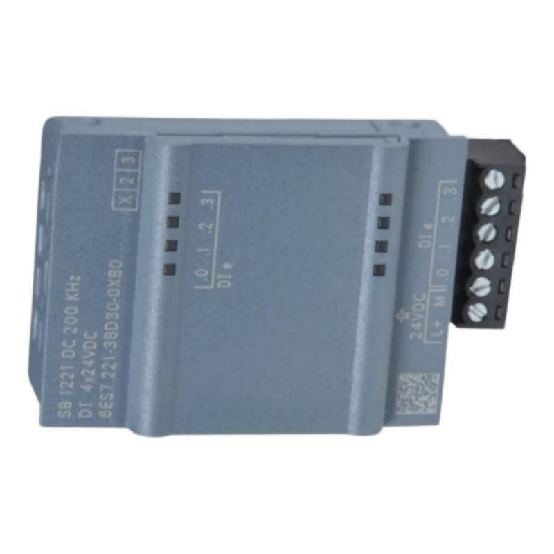
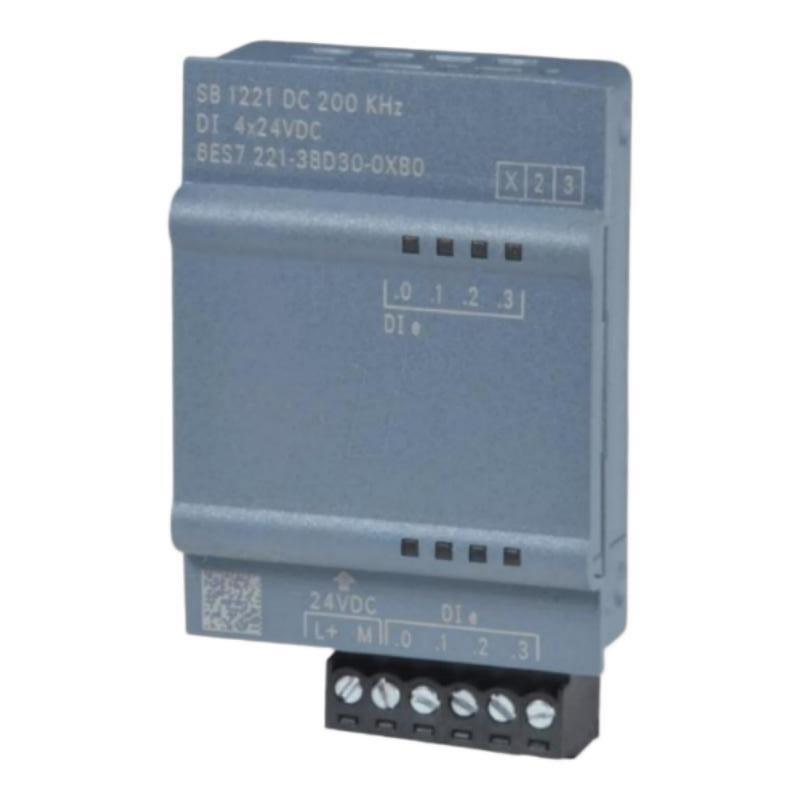
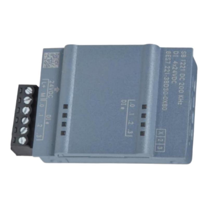
- Siemens
- 6AG1222-1AD30-5XB0
- Digital Output Module
- Germany
- 38 × 62 × 21 mm
- 0.03 kg
- Xiamen, China
- New & In Stock
- T/T, PayPal, Western Union
- 1 Year
- 1-3 Working Days
- DHL, UPS, TNT, FedEx and EMS.
- 24-Hour Service
- COO
- 4
Our advantage

Global Logistics
We have a 10-year logistics and express cooperation agreement, so our products can be shipped to any place in the world.

Brand new and original
Our products are imported in bulk from the place of origin. Because of the cooperative relationship, our products are all original and 100% new.

24-hour service
We provide 7*24 hours service to our customers. We will be there whenever you need us.

Price advantage
All our products are priced very favorably because we have our own warehouse and supply.
| Company Information | |||
| [email protected] | |||
| Mobile | +8615980777398 | ||
| +8615980777398 | |||
| 15980777398 |
Product Overview
The Siemens 6AG1222-1AD30-5XB0 Digital Output Module is identified by its supplied product description as a digital output component for industrial automation systems. Digital output modules provide an interface between a programmable logic controller (PLC) and external devices, allowing programmed control commands to be translated into discrete electrical output states.
In automated manufacturing and process control, PLCs frequently need to activate or deactivate equipment in response to operating conditions. Typical applications include controlling indicator lamps, interface relays, solenoid valves, signaling devices, and other compatible loads. A digital output module supports these functions by making the controller’s logic available to the connected field circuits.
The Siemens 6AG1222-1AD30-5XB0 has supplied dimensions of 38 × 62 × 21 mm and a weight of approximately 0.03 kg. Its compact physical size may be advantageous in installations where available mounting space is limited. However, the exact product family, output technology, electrical ratings, and installation method should be confirmed against the complete order number before integration.
A digital output module does not independently determine the required machine action. Instead, it operates under the control of the associated PLC program and responds to commands generated by the control system. Correct operation therefore depends on suitable hardware configuration, compatible field devices, appropriate electrical protection, and properly designed control logic.
Technical Specifications
| Parameter | Specification |
|---|---|
| Manufacturer | Siemens |
| Model / Order Number | 6AG1222-1AD30-5XB0 |
| Product Type | Digital Output Module |
| Product Category | PLC Output / Industrial Automation |
| Primary Function | Discrete output signal control |
| Output Technology | Verify from the exact product documentation |
| Number of Output Channels | Requires confirmation |
| Rated Output Voltage | Requires confirmation |
| Maximum Output Current | Requires confirmation |
| Output Protection | Verify according to the specific hardware |
| Control Interface | Compatible PLC or automation system, subject to verification |
| Dimensions | 38 × 62 × 21 mm |
| Weight | 0.03 kg |
| Installation | Verify the specified mounting and connection method |
| Typical Applications | Machine control, equipment signaling, and discrete automation tasks |
The dimensions and weight above are based on the supplied product information. Electrical characteristics, output-channel count, switching behavior, supported load types, and controller compatibility must be verified using the exact Siemens order number and applicable hardware documentation.
What Is the Siemens 6AG1222-1AD30-5XB0?
A digital output module is an automation interface that allows a controller to issue discrete commands to external electrical circuits. Depending on its design, a digital output may switch between defined active and inactive states to control a compatible field device.
For example, a PLC may activate an indicator when a machine is ready, energize an interface relay when a process step is complete, or command a solenoid valve to change state. The digital output module provides the output interface, while the PLC program determines when the command should be issued.
A typical control sequence can be represented as:
Sensors and Operator Inputs → PLC Logic → Digital Output Module → Field Device → Machine or Process Response
The precise signal path depends on the controller architecture and the module’s electrical design. Output devices must be selected to match the module’s voltage, current, switching characteristics, and load requirements.
Function and Working Principle
1. Receiving Control Commands
The PLC executes its control program using information from sensors, operator commands, timers, internal logic, and other configured variables. When the program determines that an output action is required, it updates the corresponding output command.
The digital output module receives or applies the configured output state through its supported control-system interface.
2. Switching the Output State
The module changes its output state according to the command and its hardware design. Depending on the verified output technology, switching may use electronic semiconductor components or another specified arrangement.
The exact switching method is important when selecting compatible loads. Different output technologies have different electrical characteristics and limitations, so they should not be treated as interchangeable.
3. Activating External Devices
When an output is activated, the connected circuit can energize a compatible device or transmit a discrete command to another control component.
Typical examples include:
- Indicator lamps and status lights
- Interface relays
- Compatible solenoid valves
- Discrete signaling devices
- Control-circuit inputs on other equipment
- Other loads approved for the module’s output specifications
The connected device must remain within the module’s permitted electrical limits. Loads with high inrush current or inductive characteristics may require additional interface or suppression components.
4. Coordinating Automated Sequences
Digital outputs allow the PLC to control equipment in a defined order. For instance, a controller may command a valve to open, wait for a position sensor to confirm movement, and then enable the next step of a machine sequence.
The output module executes the requested switching action, while the PLC logic coordinates timing, interlocks, and feedback.
5. Supporting Equipment Status and Signaling
Digital outputs can also be used to communicate operating conditions to local indicators or other compatible control equipment. This makes it easier for operators to identify machine states, recognize process transitions, and respond to abnormal conditions.
Actual diagnostic and status-reporting capabilities depend on the specific module and host system.
Role in Industrial Control Systems
Within an industrial automation architecture, a digital output module forms part of the path from control logic to physical action. It allows software-defined decisions to affect external equipment through an appropriate electrical interface.
| System Component | Typical Function |
|---|---|
| PLC or Controller | Executes programmed control logic |
| Digital Input Module | Acquires discrete signals from field devices |
| Digital Output Module | Delivers discrete control signals to compatible circuits |
| Interface Relay | Provides switching or electrical interface functions when required |
| Solenoid Valve | Controls a compatible fluid or pneumatic circuit |
| Indicator Lamp | Displays equipment status |
| Motor Starter or Drive Interface | Receives control commands through an appropriate interface |
| Terminal Blocks | Organize field wiring |
| Power Supply | Provides the required control-circuit power |
| HMI Panel | Displays operating conditions and alarms |
The components listed above represent general automation-system functions. They are not a declaration that every specific device is directly compatible with the 6AG1222-1AD30-5XB0.
Industrial Applications
Manufacturing and Assembly Equipment
Manufacturing machinery often requires discrete commands for clamping, positioning, transfer, signaling, and sequence control. A digital output module can operate compatible interface circuits under the PLC’s program.
Packaging Machinery
Packaging systems may use discrete outputs to command actuators, indicate operating states, or coordinate different machine sections. The PLC combines these output commands with sensor feedback to maintain the required sequence.
Conveyor Systems
Conveyors may require commands for start/stop interfaces, diverter mechanisms, transfer devices, and warning indicators. Output selection depends on the connected equipment and its electrical interface.
Pneumatic and Hydraulic Control
In suitable designs, digital outputs can command compatible solenoid-valve circuits or interface relays associated with pneumatic and hydraulic equipment. The output rating and any required intermediate interface must be checked before connection.
Industrial Signaling
Indicator lamps, audible alarms, and other signaling devices can communicate machine status or abnormal operating conditions. A PLC can update these outputs according to configured process conditions and alarm logic.
Process Automation
Discrete output signals are used in many process-control systems to command equipment, coordinate operating sequences, and transmit status-related actions. Applications involving critical protective functions require an appropriately engineered and validated safety system.
Installation and System Integration
Correct installation begins with confirming the product identity and the electrical requirements of the intended application.
Confirm the Complete Order Number
Check the hardware label and system records to ensure the installed or replacement component is identified as 6AG1222-1AD30-5XB0. Similar model numbers may refer to modules with different electrical characteristics or installation requirements.
Confirm the product family, hardware revision, and supported mounting arrangement before proceeding.
Verify Output Electrical Characteristics
Before connecting a load, establish the module’s actual specifications, including:
- Rated output voltage
- Permitted voltage range
- Maximum current per channel
- Total permissible output current
- Output technology and switching behavior
- Supported load types
- Short-circuit or overload protection
- Inductive-load requirements
- Required external power supply
These values must come from the exact hardware documentation. Do not select a load based solely on the product name or physical dimensions.
Prepare the Installation
Install the module according to the specified mounting and connection instructions. Ensure the surrounding equipment provides appropriate environmental protection and that sufficient space remains for wiring and maintenance.
Follow the applicable electrical isolation and lockout procedures before working on the control cabinet. Use appropriate electrostatic-discharge precautions when handling sensitive electronic assemblies.
Connect the Field Loads
Use the correct wiring diagram and terminal assignment. Verify supply polarity, common connections, conductor sizing, and any required protective devices.
For inductive loads such as coils, determine whether suppression components or an intermediate relay are necessary. The choice must be compatible with the output technology and the connected load.
Do not connect a motor or another high-power load directly to a low-power control output unless the hardware specifications explicitly permit the arrangement.
Configure the PLC
Select the correct module in the engineering environment if hardware configuration is required. Assign the appropriate output addresses and verify that the software configuration matches the installed hardware.
Review the output logic, interlocks, startup behavior, and expected state during faults or controller transitions. Output behavior during power loss or communication failure should be understood before commissioning.
Commission the Output Channels
Test each configured output under controlled conditions. Confirm that the PLC command produces the expected electrical state and that the connected field device responds correctly.
Record the output address, connected load, expected operating state, and commissioning result. For safety-related applications, follow the validated safety design and applicable testing procedures rather than relying on a standard digital output alone.
Troubleshooting the Siemens Digital Output Module
When an output fails to operate as expected, inspect the control command, module configuration, electrical supply, wiring, and connected load before replacing the hardware.
Output Does Not Activate
Possible causes include:
- PLC logic does not issue the required command
- Incorrect output address
- Hardware configuration mismatch
- Missing or incorrect field-circuit supply
- Loose or disconnected wiring
- Output protection has operated
- Connected load has failed
- Module hardware fault
Start by checking the PLC’s commanded output state and available diagnostic information. Then verify the field-circuit supply and wiring against the correct diagram.
Output Remains Permanently Active
An output that remains active may be associated with incorrect program logic, an unintended force or override, wiring errors, an external circuit issue, or a hardware fault.
Review the PLC program and engineering-tool status. Check for active forcing or maintenance overrides according to site procedures, and inspect the field circuit before concluding that the module is defective.
Output Activates but the Device Does Not Respond
This condition can result from a failed field device, incorrect load wiring, insufficient supply voltage, an open circuit, a blown protective device, or an output that cannot supply the required load current.
Measure the circuit using an appropriate instrument and qualified procedures. Compare the observed voltage and current with the verified module and load specifications.
Output Trips or Repeatedly Fails
Repeated output faults may indicate excessive current, a short circuit, an unsuitable load, inadequate suppression of inductive transients, or a problem in the field wiring.
Disconnecting loads and testing circuits must follow approved maintenance procedures. Do not repeatedly reset a fault without identifying its cause, as continued operation may damage the module or connected equipment.
Output Status and Physical Behavior Do Not Match
If the software indicates an active command but the field device remains inactive, examine the entire output path. This includes the output address, wiring, supply source, protective components, interface relays, and final device.
If the electrical output is correct but the device does not respond, the fault may lie downstream of the module.
Maintenance Recommendations
Regular inspection helps maintain reliable output switching and reduces unnecessary component replacement.
Inspect wiring and terminals. Look for loose connections, damaged insulation, discoloration, and signs of overheating.
Check connected loads. Confirm that actuators, relays, lamps, and other field devices operate within their specified electrical requirements.
Review recurring faults. Record output failures, overload events, and unexpected switching behavior where the system provides relevant diagnostics.
Maintain cabinet conditions. Keep the installation within the specified environmental limits and prevent excessive dust, moisture, vibration, and heat.
Verify configuration records. Maintain accurate output-address lists, wiring diagrams, load descriptions, and hardware-replacement records.
Follow safe maintenance practices. Isolate the equipment as required and use suitable test equipment before handling wiring or replacing electronic components.
Maintenance intervals should reflect the operating environment, equipment manufacturer’s recommendations, and the importance of the controlled process.
Compatible System Components
A digital output module may be integrated with several types of automation hardware, provided that the exact product and system architecture support the arrangement.
| Component Type | Purpose |
|---|---|
| Compatible Siemens PLC | Generates control commands |
| Digital Input Module | Acquires field feedback |
| Additional Output Modules | Expands discrete control capacity where supported |
| Interface Relays | Switch compatible circuits or provide electrical separation when required |
| Solenoid Valves | Operate compatible pneumatic or hydraulic functions |
| Indicator Lamps | Display operating states |
| Terminal Blocks | Organize and distribute field wiring |
| Industrial Power Supply | Supplies the required control and load circuits |
| HMI Panel | Provides operator control and status visualization |
| Engineering Software | Supports hardware configuration and diagnostics |
Compatibility must be confirmed from the exact order number, controller family, electrical ratings, and supported hardware configuration. The table describes typical component roles rather than guaranteed direct compatibility with particular models.
Replacement and Procurement Considerations
When sourcing a replacement for the Siemens 6AG1222-1AD30-5XB0, confirm the full order number and the actual product designation before placing an order.
Key checks include:
- Complete order number and hardware revision
- Output technology
- Number of channels
- Rated voltage and current
- Permitted load types
- Terminal and connector arrangement
- Controller compatibility
- Mounting requirements
- Availability of required accessories
The supplied dimensions of 38 × 62 × 21 mm and weight of 0.03 kg can assist with inventory records and preliminary space planning. Physical measurements alone do not establish electrical or functional interchangeability.
If the module is replacing an existing unit, record the original wiring and output assignments before removal. After installation, verify the hardware configuration and test each connected output before returning the equipment to normal operation.
Key Advantages
Discrete Control Interface
A digital output module provides a structured way for a compatible controller to operate external devices using programmed ON/OFF commands.
Support for Automated Sequences
Digital outputs allow the PLC to coordinate actuators, indicators, and control interfaces according to defined process logic.
Integration with Equipment Monitoring
When combined with suitable input feedback, output commands can form part of a control sequence that checks whether the expected physical response has occurred.
Compact Physical Dimensions
The supplied dimensions of 38 × 62 × 21 mm and weight of 0.03 kg may be beneficial for installations where compact hardware is desirable, subject to the actual mounting requirements.
Maintainable Control Architecture
Clearly documented output assignments, wiring, and commissioning tests make the system easier to inspect and troubleshoot.
Technical FAQs
What is the Siemens 6AG1222-1AD30-5XB0?
It is identified in the supplied description as a Siemens digital output module for discrete control functions in an industrial automation system. Its exact electrical characteristics and system compatibility should be confirmed using the complete order number.
What does a digital output module do?
It allows a PLC or compatible controller to issue discrete electrical commands to suitable external circuits, such as indicator devices, interface relays, or compatible actuators.
What are the dimensions of the 6AG1222-1AD30-5XB0?
The supplied dimensions are 38 × 62 × 21 mm.
How much does the module weigh?
The supplied weight is approximately 0.03 kg.
How many output channels does it provide?
The output-channel count should be confirmed from the exact product documentation. It should not be inferred from the general product description.
What voltage and current can the outputs handle?
The rated voltage, maximum current, and permitted load types require verification against the exact hardware specifications before wiring or selecting field devices.
Can it directly control a motor?
A digital output should not be assumed to support direct motor switching. Motor control normally requires a suitably rated starter, contactor, drive, or other approved interface unless the module’s specifications explicitly permit the intended load.
What should be checked if an output does not work?
Check the PLC command, output address, hardware configuration, field-circuit supply, wiring, protection devices, connected load, and available diagnostics. Compare the measured electrical conditions with the verified specifications.
Can another Siemens output module replace it?
Not automatically. A replacement must match the required electrical characteristics, output technology, channel configuration, terminal arrangement, and controller compatibility.
Conclusion
The Siemens 6AG1222-1AD30-5XB0 Digital Output Module is described as a discrete output interface for industrial automation systems. Digital output functionality enables a compatible controller to operate external devices, coordinate machine sequences, manage signaling, and implement programmed control responses.
With supplied dimensions of 38 × 62 × 21 mm and a weight of 0.03 kg, the module has a compact physical profile for suitable automation installations. Reliable integration depends on confirming the exact product identity, checking the output ratings, selecting compatible loads, wiring the field circuits correctly, and validating the PLC configuration.
For installation, troubleshooting, or replacement, the complete Siemens order number should be verified before work begins. Careful electrical checks, documented commissioning, and appropriate maintenance procedures help support dependable output operation and long-term industrial control-system reliability.