

ProductPRODUCT
Featured products
Contact Us
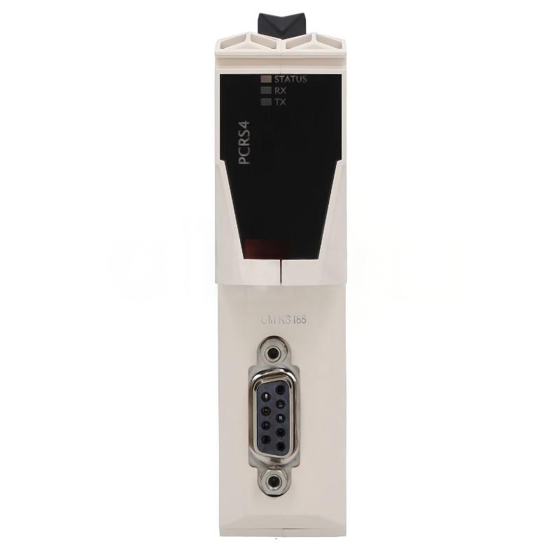
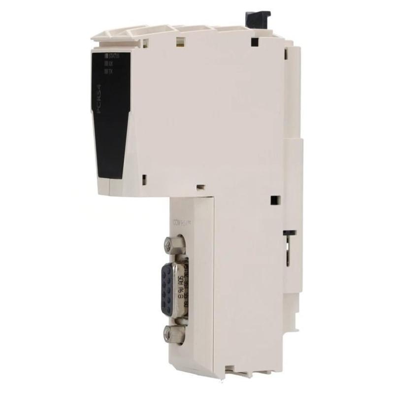
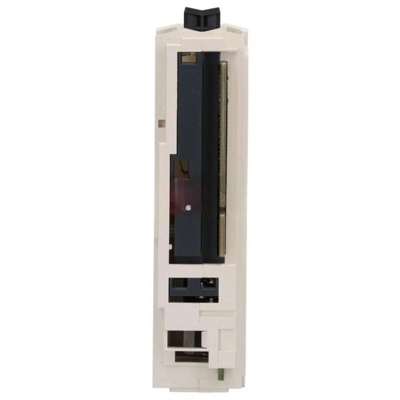
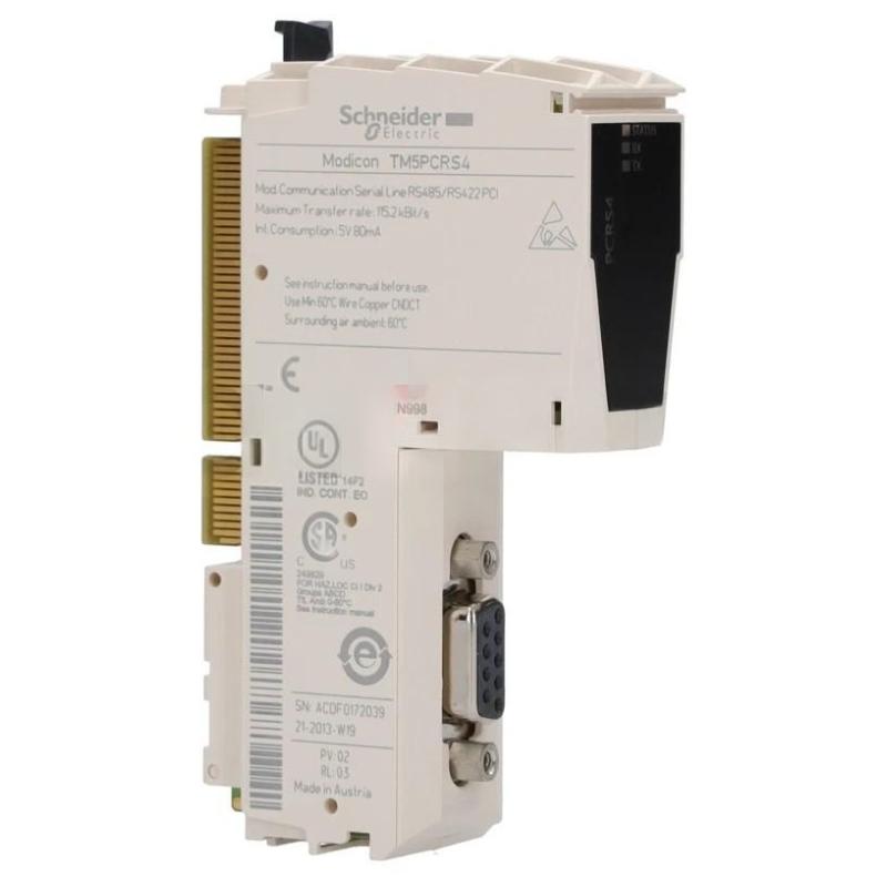
- Schneider
- TM5PCRS4
- Serial Link Communication Module
- France
- 99 × 37.5 × 75 mm
- 0.05 kg
- Xiamen, China
- New & In Stock
- T/T, PayPal, Western Union
- 1 Year
- 1-3 Working Days
- DHL, UPS, TNT, FedEx and EMS.
- 24-Hour Service
- COO
- 6
Our advantage

Global Logistics
We have a 10-year logistics and express cooperation agreement, so our products can be shipped to any place in the world.

Brand new and original
Our products are imported in bulk from the place of origin. Because of the cooperative relationship, our products are all original and 100% new.

24-hour service
We provide 7*24 hours service to our customers. We will be there whenever you need us.

Price advantage
All our products are priced very favorably because we have our own warehouse and supply.
| Company Information | |||
| [email protected] | |||
| Mobile | +8615980777398 | ||
| +8615980777398 | |||
| 15980777398 |
Product Overview
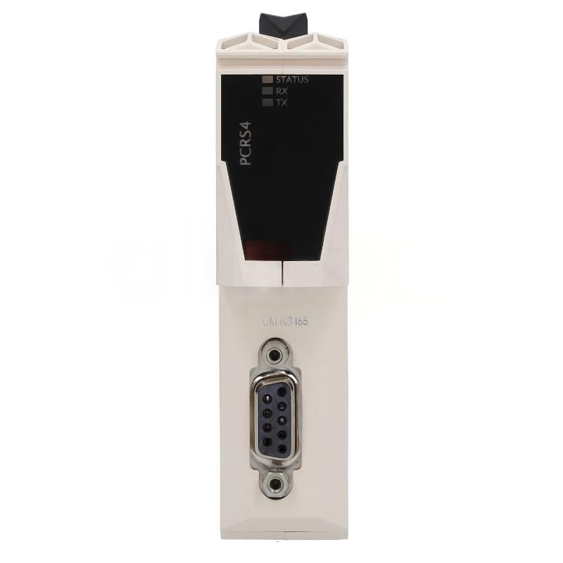
The Schneider Electric TM5PCRS4 Serial Link Communication Module is an industrial automation component identified for serial communication and connectivity applications within compatible control systems. Communication interfaces play an important role in modern automation by enabling controllers, field devices, and peripheral equipment to exchange operational data and status information.
In industrial environments, serial communication remains useful for connecting devices that require structured data exchange over a wired interface. Depending on the equipment and network configuration, serial links may support controller-to-device communication, equipment monitoring, parameter exchange, and integration with selected automation peripherals.
The TM5PCRS4 belongs to the Schneider Electric product identification provided for this article. Its listed dimensions are 99 × 37.5 × 75 mm, and its listed weight is 0.05 kg. This compact size can be beneficial in control cabinets where space is limited and communication hardware must be integrated alongside controllers, I/O modules, power supplies, and field wiring.
Before incorporating this module into an existing installation, it is important to verify the complete part number, supported communication standard, connector pinout, electrical interface, and compatibility with the host controller. The precise interface characteristics should be confirmed using the applicable product documentation rather than inferred from the description alone.
Technical Specifications
| Parameter | Specification |
|---|---|
| Manufacturer | Schneider Electric |
| Model | TM5PCRS4 |
| Product Type | Serial Link Communication Module |
| Product Category | Industrial Automation Communication |
| Primary Function | Serial communication interface |
| Communication Interface | Serial link; exact standard and configuration require verification |
| System Role | Data exchange between compatible automation devices |
| Dimensions | 99 × 37.5 × 75 mm |
| Weight | 0.05 kg |
| Installation | Verify mounting and connection requirements for the exact product |
| Typical Applications | Industrial communication, equipment integration, and control-system connectivity |
| Compatibility | Confirm against the host controller and supported hardware configuration |
The table includes the product identification and physical specifications supplied for this model. Communication protocol, baud rate, connector type, supported topology, isolation, and other electrical parameters should be verified before installation.
What Is the Schneider TM5PCRS4?
A serial communication module provides an interface through which compatible devices can exchange data over a serial connection. Rather than transmitting information through separate electrical signals for every individual data item, serial communication transfers data in an organized sequence according to the interface and protocol being used.
In an industrial automation system, this type of communication can help connect controllers with compatible instruments, peripheral devices, or other equipment. The actual application depends on the communication capabilities of the module and the devices connected to it.
The TM5PCRS4 is identified as a serial link communication module. Its exact role in a particular Schneider Electric architecture should be confirmed from the full product designation and system documentation, especially before selecting cables, configuring software, or planning a replacement.
A general serial communication arrangement can be represented as:
Controller → Serial Communication Interface → Communication Cable → Compatible Device
The connected devices must share compatible electrical characteristics and communication settings. A physical connection alone does not guarantee that two devices can exchange valid data.
Function and Working Principle
1. Serial Data Exchange
Serial communication transfers data sequentially between connected devices. Depending on the supported interface, the data may include operating parameters, equipment status, commands, measurements, or diagnostic information.
The communication module provides the interface required by the associated control architecture. The supported data format and communication behavior depend on the exact hardware and protocol.
2. Communication Interface
The physical interface establishes the electrical connection between the module and the external device or communication network. Connector arrangement, signal assignment, electrical levels, and grounding requirements must be confirmed before connecting the equipment.
Using the correct cable and pinout is essential. Incorrect wiring may prevent communication and can potentially damage an interface if incompatible electrical signals are applied.
3. Protocol and Parameter Configuration
Serial communication generally requires compatible settings at both ends of the connection. Depending on the interface, these may include transmission speed, data bits, parity, stop bits, addressing, and protocol-specific parameters.
The settings supported by the TM5PCRS4 should be checked in the relevant technical documentation. Configuration should not be based on assumptions drawn from a different serial communication module.
4. Data Interpretation
The receiving device interprets the transmitted data according to the applicable protocol and configuration. When the communication settings match, the devices can exchange information in a format that the controller or application software can use.
If the settings do not match, communication may fail completely or produce incomplete and invalid data.
5. Integration with Control Logic
Where supported by the host system, serial communication data can be incorporated into automation logic. A controller may use received information to monitor a device, evaluate operating conditions, update internal variables, or coordinate equipment operation.
The communication interface transfers information; the controller program determines how that information is used.
Role in Industrial Control Systems
The Schneider TM5PCRS4 can be considered within the broader context of industrial communication, where reliable data exchange connects control hardware with compatible external equipment.
A typical automation architecture may include controllers, distributed I/O, operator interfaces, instruments, drives, and communication interfaces. Each component performs a distinct function, and the communication design determines how information moves between them.
The role of a serial communication module may include:
- Establishing a supported serial connection
- Transferring data between compatible devices
- Supporting equipment status monitoring
- Enabling parameter exchange where supported
- Connecting legacy or specialized serial equipment
- Helping integrate communication-capable peripherals
- Supporting diagnostics when the host system provides the necessary tools
These are general functions of serial communication interfaces. The specific functions available with the TM5PCRS4 depend on its verified hardware capabilities and intended host system.
Industrial Applications
Manufacturing Equipment
Industrial machines often combine controllers with peripheral equipment that exchanges status information and operating parameters. A suitable serial communication interface can help integrate compatible devices into the control architecture.
Packaging Machinery
Packaging systems may contain instruments and specialized equipment that communicate with the main controller. Where the connected device and module support the required interface, serial communication can assist with data exchange and equipment monitoring.
Process Automation
Selected process instruments and control devices use serial interfaces to exchange operating data. Integration requires confirmation of the protocol, electrical interface, and data format supported by each device.
Equipment Monitoring
Communication links can provide access to status information, operating values, and diagnostic data when these functions are supported by the connected equipment. This information can help maintenance personnel identify communication faults or abnormal operating conditions.
Industrial System Upgrades
Some automation installations include equipment from different generations. A suitable serial interface may help integrate supported devices into an existing architecture, provided that protocol compatibility and system requirements are satisfied.
Control Cabinet Integration
The listed dimensions of 99 × 37.5 × 75 mm make the module’s physical size relevant when planning cabinet layouts. Actual installation suitability depends on its approved mounting method, required clearance, connector access, and environmental requirements.
Installation and System Integration
Correct installation begins with confirming the module’s identity and its intended place in the control architecture.
Verify the Model Number
Check the product label for the complete designation TM5PCRS4. Compare it with the installed hardware, system inventory, and engineering records before ordering or replacing the unit.
Do not assume that modules with similar names or dimensions have the same electrical interface or are interchangeable.
Confirm Host-System Compatibility
Verify that the module is supported by the intended controller and hardware configuration. Check the required mounting arrangement, supported firmware or engineering software, and any additional hardware needed for operation.
The physical fit of a module does not establish functional compatibility.
Check the Electrical Interface
Before wiring, confirm the serial interface type, terminal or connector assignment, signal levels, grounding requirements, and any isolation requirements specified for the product.
Use the correct cable and follow the approved wiring diagram. Avoid connecting a device based only on a connector that appears physically compatible.
Configure Communication Parameters
Where configuration is required, make sure both communication endpoints use compatible settings. Depending on the supported interface, parameters may include transmission speed, parity, data bits, stop bits, addressing, and protocol options.
Record the configured values so that maintenance personnel can reproduce the settings during future service work.
Inspect Cable Routing
Route communication cables according to the installation requirements. Where necessary, keep communication wiring separated from high-power conductors and sources of electrical interference.
Inspect cable condition, connector seating, grounding, and strain relief. Damaged cables and loose connections can cause intermittent communication even when the module itself is functioning correctly.
Commission the Connection
After installation, test communication using the diagnostic facilities available in the host system. Confirm that the intended device is recognized and that data is transferred correctly.
Record the connected device, cable identification, communication settings, and test results. For critical applications, validate the system’s response to communication loss according to the approved commissioning procedure.
Troubleshooting the TM5PCRS4 Serial Link Communication Module
Communication faults may originate from the module, cable, connected device, configuration, or controller. Troubleshooting should therefore follow the complete communication path.
No Communication
Possible causes include:
- Incorrect wiring or connector assignment
- Damaged communication cable
- Missing power to the connected device
- Incompatible interface standards
- Incorrect communication parameters
- Unsupported protocol configuration
- Incorrect hardware configuration
- Faulty interface hardware
Start by confirming the module’s identity and checking the cable and connector arrangement. Verify that the connected device is powered and configured for the same supported interface. Review controller diagnostics before concluding that the module has failed.
Intermittent Communication
Intermittent data exchange may result from loose connectors, damaged cables, electrical interference, unstable device power, or incorrect communication settings.
Inspect the cable route and connections. If the problem occurs only when nearby machinery operates, investigate possible electrical interference and follow the installation guidance for cable shielding and routing.
Communication Errors or Invalid Data
If the connection is active but the data is incorrect, investigate protocol compatibility, device addressing, data formatting, and parameter configuration.
Confirm that the transmitting and receiving devices interpret the data using the same protocol and expected format. A successful physical connection does not necessarily mean that the devices are exchanging meaningful information.
Device Not Recognized
A device may not be recognized if the hardware configuration is incorrect, the connected device is incompatible, or the communication interface has not been configured as required.
Check the complete product designation, host-system configuration, device settings, and available diagnostic messages. Confirm compatibility before attempting a replacement.
Communication Stops After Maintenance
If communication fails after a service operation, check whether the cable was reconnected correctly, the terminal assignment was changed, or the configuration was modified.
Compare the current installation with the saved wiring and configuration records. Restore only verified settings and perform a communication test before returning the system to normal operation.
Maintenance Recommendations
Regular inspection can help maintain dependable serial communication.
Inspect connectors and cables: Check for loose connections, damaged insulation, bent contacts, and signs of moisture or contamination.
Maintain configuration records: Document communication parameters, device assignments, cable identification, and any software or hardware changes.
Review diagnostics: Record recurring communication errors and identify whether faults affect a particular device, cable, or operating condition.
Control electrical interference: Maintain appropriate cable routing, shielding, and grounding according to the system design.
Maintain cabinet conditions: Keep the equipment within its specified environmental limits and protect it from excessive dust, moisture, heat, and vibration.
Follow safe maintenance procedures: Isolate equipment as required and observe the applicable electrical and electrostatic-discharge precautions before handling the module.
Compatible System Components
The TM5PCRS4 may be used in an automation arrangement involving several functional component types. The following table describes typical roles; it does not confirm compatibility with every specific model.
| Component Type | Typical Function |
|---|---|
| Compatible Schneider Electric Controller | Executes control logic and manages supported hardware |
| Serial-Compatible Field Device | Exchanges data through a supported serial interface |
| Communication Cable | Carries serial signals between compatible devices |
| Terminal or Connector Accessories | Provide the required physical connection |
| I/O Modules | Acquire field signals or control outputs |
| Industrial Power Supply | Provides correctly rated power to the applicable equipment |
| HMI or Operator Interface | Presents operating status and alarms where integrated |
| Engineering Software | Supports configuration and diagnostics when required |
| Network or Interface Gateway | Connects different communication systems when the architecture supports it |
Before selecting accessories or related modules, verify the required interface, connector, wiring arrangement, and host-system support. A general product-family relationship should not be treated as proof of direct compatibility.
Replacement and Procurement Considerations
When sourcing a replacement for the Schneider Electric TM5PCRS4 Serial Link Communication Module, begin by checking the full part number and the original installation records.
Important verification points include:
- Complete model designation
- Product revision, where applicable
- Supported serial interface
- Connector and pinout arrangement
- Communication protocol and configuration
- Host-controller compatibility
- Mounting and clearance requirements
- Required cables and accessories
- Product condition and testing history
The supplied physical specifications are 99 × 37.5 × 75 mm and 0.05 kg. These values can support preliminary cabinet planning, inventory management, and shipping calculations, but they do not establish electrical or functional compatibility.
If the module is being replaced in an operating system, record the original wiring and configuration before removal. After installing the replacement, verify communication with the connected device and confirm that the controller receives the expected information.
Key Advantages
Serial Connectivity
A suitable serial interface allows compatible automation devices to exchange data over a wired connection.
Compact Physical Design
The listed dimensions of 99 × 37.5 × 75 mm and weight of 0.05 kg are relevant when evaluating physical space and handling requirements.
Support for Equipment Integration
Where the interface and protocol are compatible, serial communication can help connect peripheral devices to a larger control system.
Improved Diagnostic Visibility
Communication diagnostics, when supported by the host system and connected devices, can help maintenance personnel identify configuration, wiring, or device-level problems.
Organized Control-System Architecture
A correctly integrated communication module can form part of a structured automation system in which controllers and compatible peripherals exchange information through defined interfaces.
Technical FAQs
What is the Schneider TM5PCRS4?
The TM5PCRS4 is identified in the supplied product description as a serial link communication module for industrial automation applications. Its precise interface capabilities and host-system requirements should be confirmed from the exact product documentation.
What is the main function of a serial communication module?
It provides an interface for transferring data between compatible devices over a serial connection. The actual data and supported functions depend on the interface, protocol, and connected equipment.
What are the dimensions of the TM5PCRS4?
The supplied dimensions are 99 × 37.5 × 75 mm.
How much does the TM5PCRS4 weigh?
The supplied weight is 0.05 kg.
Which communication protocol does the TM5PCRS4 support?
The exact protocol should be verified using the full product designation and applicable technical documentation. It should not be inferred from the phrase “serial link” alone.
Can it connect to any serial device?
No. The module and connected device must have compatible electrical interfaces, connector assignments, communication parameters, and protocols.
What should be checked if communication fails?
Check power, cable condition, connector assignment, interface compatibility, communication settings, hardware configuration, and diagnostic messages. Investigate the complete signal path before replacing the module.
Can another Schneider Electric module replace the TM5PCRS4?
A different module should not be considered interchangeable solely because it is manufactured by Schneider Electric or has similar dimensions. Verify its interface, supported system, mounting, and configuration requirements first.
Conclusion
The Schneider Electric TM5PCRS4 Serial Link Communication Module is described as an industrial automation component intended for serial communication and data exchange within compatible control systems. Serial connectivity can support equipment integration, operating-status monitoring, and information transfer between controllers and compatible peripheral devices.
With listed dimensions of 99 × 37.5 × 75 mm and a weight of 0.05 kg, the module has a compact physical profile for suitable automation installations. Successful operation depends on correct product identification, compatible electrical interfaces, appropriate cabling, matching communication settings, and a properly configured host system.
Before installation, commissioning, or replacement, verify the full model designation and the module’s supported interface and system requirements. Careful configuration, documented wiring, and systematic testing help establish reliable communication and simplify long-term industrial maintenance.