

ProductPRODUCT
Featured products
Contact Us
- Schneider
- TM5PCRS2
- Serial Link Communication Module
- France
- 110 x 52 x 104 mm
- 0.05 kg
- Xiamen, China
- New & In Stock
- T/T, PayPal, Western Union
- 1 Year
- 1-3 Working Days
- DHL, UPS, TNT, FedEx and EMS.
- 24-Hour Service
- COO
- 5
Our advantage

Global Logistics
We have a 10-year logistics and express cooperation agreement, so our products can be shipped to any place in the world.

Brand new and original
Our products are imported in bulk from the place of origin. Because of the cooperative relationship, our products are all original and 100% new.

24-hour service
We provide 7*24 hours service to our customers. We will be there whenever you need us.

Price advantage
All our products are priced very favorably because we have our own warehouse and supply.
| Company Information | |||
| [email protected] | |||
| Mobile | +8615980777398 | ||
| +8615980777398 | |||
| 15980777398 |
Product Overview
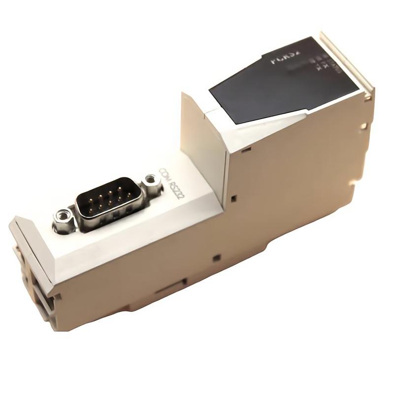
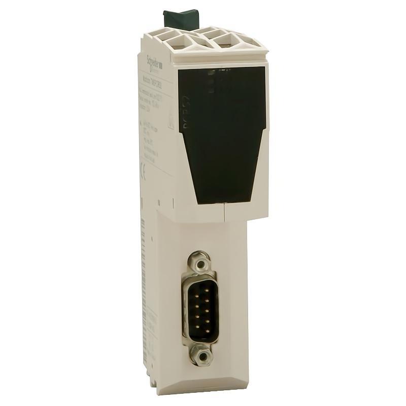
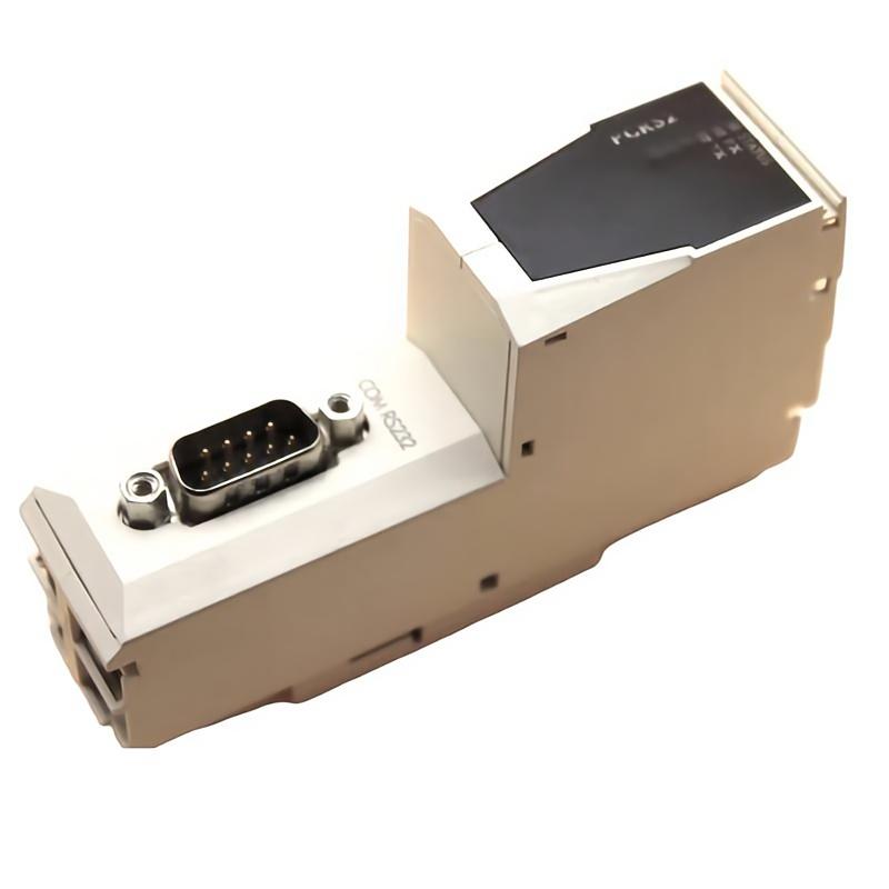
The Schneider Electric TM5PCRS2 Serial Link Communication Module is an industrial automation component designed to support serial communication within compatible control systems. Serial communication modules provide an interface for exchanging data between automation devices, controllers, operator interfaces, and other equipment that relies on a supported serial communication connection.
In industrial environments, reliable data exchange is essential for coordinating machinery, monitoring equipment status, and integrating different control-system components. Serial interfaces remain useful in applications involving legacy equipment, dedicated field devices, and automation systems that require structured communication over a wired connection.
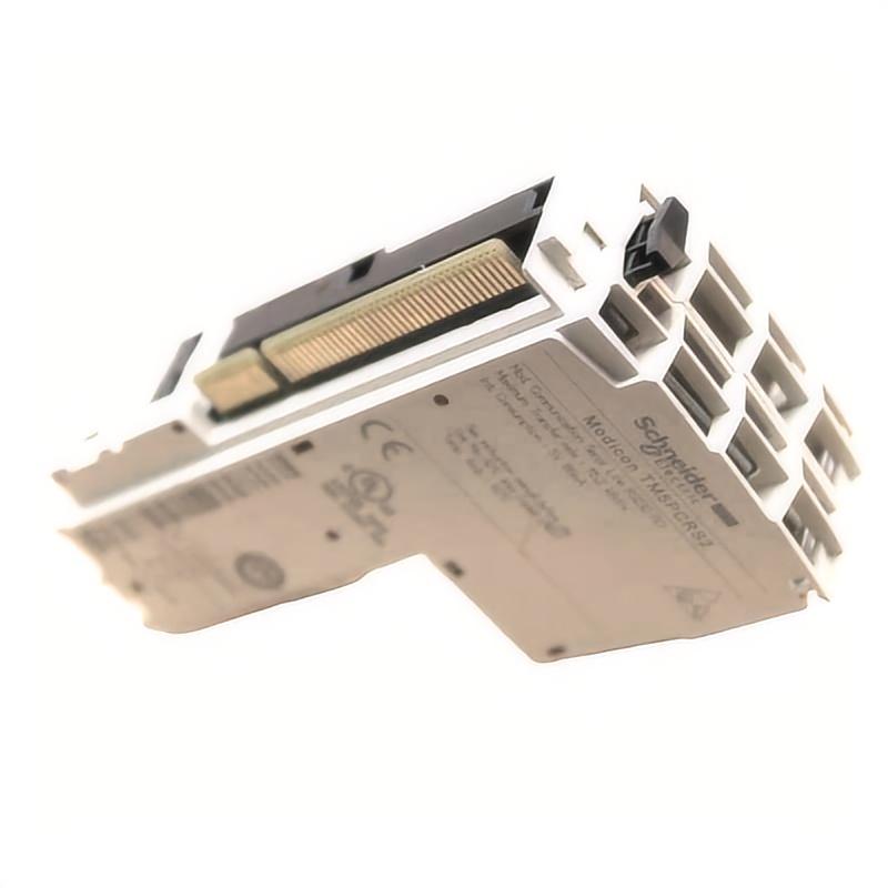
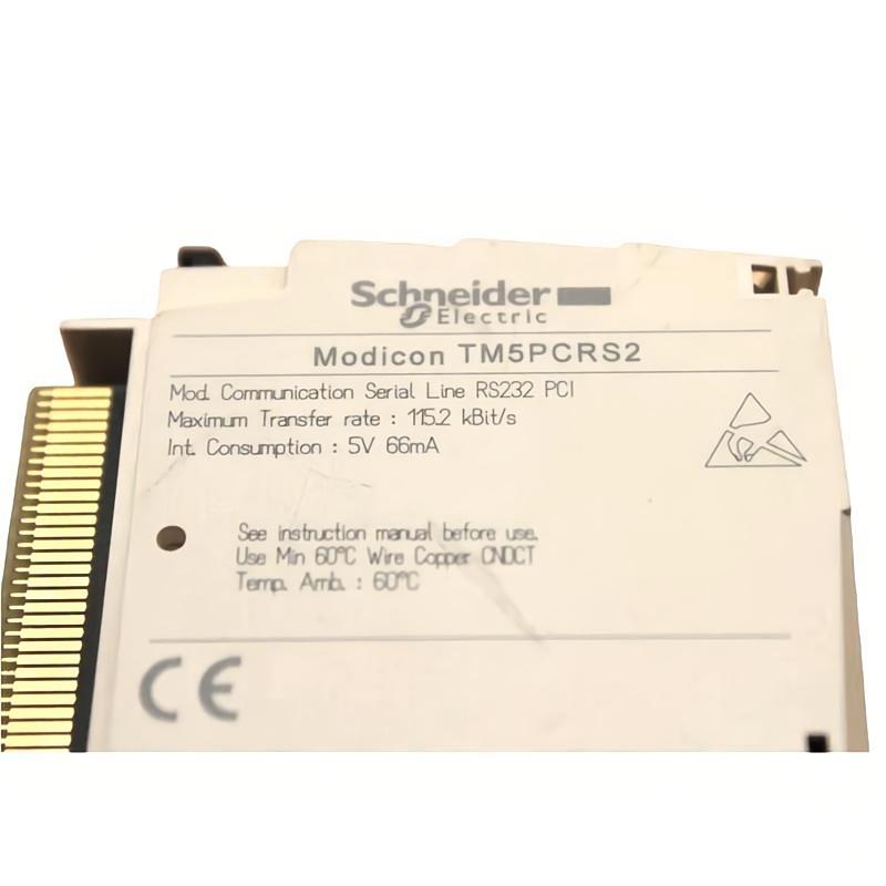
The TM5PCRS2 belongs to Schneider Electric’s TM5 product identification range. Its stated function is serial-link communication, making accurate identification of the module and its supported interface particularly important when planning an installation or replacement. The precise electrical interface, connector assignment, supported protocols, and compatible hardware configuration should be confirmed against the exact product documentation before use.
The supplied physical specifications list dimensions of 110 × 52 × 104 mm and a weight of 0.05 kg. These measurements are useful for preliminary cabinet planning, inventory management, and replacement logistics. Actual installation requirements depend on the module’s mounting arrangement and the associated control-system hardware.
Technical Specifications
| Parameter | Specification |
|---|---|
| Manufacturer | Schneider Electric |
| Model | TM5PCRS2 |
| Product Type | Serial Link Communication Module |
| Product Family | TM5 identification range |
| Primary Function | Serial communication interface |
| Communication Category | Industrial serial communication |
| System Role | Data exchange between compatible automation devices |
| Dimensions | 110 × 52 × 104 mm |
| Weight | 0.05 kg |
| Installation | Verify the supported mounting arrangement and hardware configuration |
| Typical Applications | Industrial equipment communication and automation integration |
| Interface Details | Confirm the exact electrical interface and connector assignment |
| Protocol Support | Verify against the applicable product documentation |
| Compatibility | Confirm the controller, system configuration, and associated accessories |
The specifications above distinguish the supplied product information from details that require verification. The exact serial standard, baud-rate range, connector type, isolation characteristics, and supported communication protocols should not be assumed from the model name alone.
What Is the Schneider TM5PCRS2?
The Schneider TM5PCRS2 is identified as a serial-link communication module. In an industrial control system, a communication interface provides a path for transferring information between devices that need to exchange commands, status values, configuration information, or diagnostic data.
Unlike a digital input module, which primarily acquires discrete electrical states, a serial communication module is concerned with transferring structured data between compatible devices.
For example, an automation controller may need to exchange operating information with an external instrument, a communication-capable device, or another system component. Where the equipment and interface are compatible, serial communication can provide the data link required for that exchange.
A simplified communication path is:
Automation Controller → Serial Communication Interface → Serial Connection → Compatible Device
The actual arrangement depends on the supported interface, wiring topology, protocol, and configuration of the installed system.
Function and Working Principle
1. Serial Data Transmission
Serial communication transfers information sequentially over a communication link. Depending on the interface standard, data may be transmitted using one or more signal conductors together with the required reference, return, or control connections.
A serial link can be useful where devices need to exchange information through a defined wired interface without requiring a high-bandwidth industrial Ethernet connection.
The TM5PCRS2’s precise transmission characteristics should be checked against the official specification for the exact part number.
2. Communication Interface
A communication module provides the electrical and logical interface needed to connect compatible devices. The module’s interface must match the requirements of the connected equipment.
Relevant considerations may include signal levels, connector arrangement, wiring topology, grounding, and supported communication settings. An interface mismatch can prevent successful communication even when the physical connectors appear similar.
3. Data Exchange
Once compatible devices are connected and correctly configured, the serial link can carry data according to the communication method supported by the system.
Depending on the application, exchanged information may include status data, measured values, commands, or diagnostic messages. The available data and command structure depend on the connected device and communication protocol rather than the physical interface alone.
4. Communication Configuration
Serial communication commonly requires matching settings at both ends of the connection. Depending on the supported interface, these may include transmission speed, data format, parity, stop bits, device addressing, and protocol-specific parameters.
The exact settings available for the TM5PCRS2 must be confirmed from the applicable product documentation and engineering configuration.
5. Integration with Control Logic
When communication is established, the controller can use the received data as part of its control program. The application may monitor external equipment, exchange operating information, or coordinate a process with another compatible device.
The communication module provides the data-transfer path; the controller program determines how the information is interpreted and used.
Role in Industrial Automation Systems
Communication interfaces help connect separate devices into a coordinated automation architecture. In many installations, controllers must exchange information with instruments, operator interfaces, external equipment, or other control-system components.
A serial-link module may contribute to this architecture by providing a suitable communication interface for compatible equipment.
| System Component | Typical Role |
|---|---|
| PLC or Automation Controller | Executes control logic and manages application data |
| Serial Communication Module | Provides the supported serial communication interface |
| External Serial Device | Sends or receives data over a compatible connection |
| Operator Interface | Displays operating information and allows authorized commands |
| Industrial Instrument | Supplies measurements or status information when supported |
| Communication Cable | Connects devices using the specified wiring arrangement |
| Engineering Software | Supports system configuration and diagnostics |
| Power Supply | Provides the electrical power required by the installed equipment |
The exact arrangement depends on the host system and the connected devices. Not every serial device can communicate directly with every controller, and protocol compatibility must be established before integration.
Industrial Applications
Machine Automation
Serial communication may be used to exchange information between a controller and compatible machine components. Depending on the system, this can support parameter access, status monitoring, or coordination with external equipment.
Industrial Instrumentation
Some industrial instruments provide serial interfaces for transmitting measured values, operating status, and diagnostic information. A compatible communication arrangement can allow these data to be incorporated into the wider control system.
Legacy Equipment Integration
Industrial facilities often operate equipment installed at different times. Where the electrical interface and communication protocol are compatible, serial communication can help connect existing devices to a broader automation system.
Compatibility must be checked carefully, especially when the connected device uses an older or proprietary protocol.
Equipment Monitoring
A control system may use serial data from compatible devices to monitor operating conditions and detect abnormal status information. The actual monitoring functions depend on the connected device and the application software.
Industrial Control Panels
A serial communication module can form part of a control panel where an approved serial connection is required. Proper mounting, cable routing, grounding, and configuration help support dependable communication.
System Modernization
During automation upgrades, serial communication may be retained when replacing all connected equipment would be impractical. The interface, protocol, performance requirements, and long-term support arrangements should be assessed before adopting this approach.
Installation and System Integration
Correct installation begins with verifying the complete module identity and the requirements of the host automation platform.
Verify the Model Number
Confirm that the installed or replacement component is marked TM5PCRS2. Check the complete product identification, revision information where applicable, and associated hardware documentation.
Do not select a replacement solely because it has a similar enclosure or connector arrangement.
Confirm System Compatibility
Before installation, verify that the host controller and the relevant hardware configuration support the module. Check the required mounting arrangement, connection method, configuration procedure, and any required accessories.
The product’s designation alone is not sufficient to establish compatibility with every Schneider Electric controller.
Verify the Serial Interface
Identify the actual electrical interface and connector assignment from the applicable documentation. Confirm that the connected device uses a compatible interface and that the correct cable and wiring topology are selected.
Never assume a particular serial standard or pin assignment without checking the product specification.
Prepare the Installation Environment
Install the module according to the host system’s mounting and environmental requirements. Maintain adequate space for wiring and maintenance, and route communication cables to reduce exposure to electrical interference.
Where required by the installation design, keep communication wiring separated from motor cables, contactor wiring, and other sources of electrical noise.
Configure Communication Parameters
Configure the controller and connected device using the settings supported by the interface and protocol. Verify that both ends use compatible transmission parameters, addressing, and data formats.
Incorrect configuration may cause communication failures, corrupted data, or intermittent connections.
Commission the Connection
After installation, check the physical connection and power status. Use the available controller diagnostics and device indicators to determine whether the link is operating as expected.
Perform a controlled data-exchange test and verify that received values or status information match the connected device’s actual operating state. Record the configuration and test results for future maintenance.
Troubleshooting the TM5PCRS2 Serial Link Communication Module
Communication faults may originate from the module, the connected device, the wiring, the controller configuration, or the protocol settings. A systematic investigation helps isolate the cause.
No Communication
Possible causes include:
- Incorrect wiring or pin assignment
- Loose or damaged connectors
- Incompatible electrical interfaces
- Incorrect communication parameters
- Unsupported protocol configuration
- Incorrect device addressing
- Missing device power
- Hardware configuration errors
Start by confirming the module identity and the wiring diagram. Verify the power status of both devices, then compare the communication settings and address configuration. Check available diagnostic information before replacing hardware.
Intermittent Communication
Intermittent data exchange may result from loose connections, damaged cables, electrical interference, grounding problems, unstable power, or mismatched communication settings.
Inspect the cable route and connectors, particularly where wiring passes near high-power equipment. Review diagnostic messages and communication-error records where available.
If the problem occurs only when machinery operates, investigate possible electrical interference and grounding issues without changing wiring arrangements outside approved procedures.
Incorrect or Incomplete Data
Incorrect data may be caused by mismatched data formats, incompatible protocol settings, incorrect register or variable mapping, or an incorrect interpretation of the received information.
Confirm the communication protocol and the data structure used by both devices. Compare the transmitted information with the receiving controller’s configuration and application logic.
A stable physical connection does not necessarily mean that the application-level data mapping is correct.
Device Not Recognized
If the controller does not recognize the installed module or the expected device, check the hardware configuration, supported system architecture, module seating, and connector condition.
Confirm that the configured hardware corresponds to the physical unit and that any required configuration steps have been completed.
Communication Errors After Replacement
When a module has recently been replaced, compare the old and new hardware identification, connection arrangement, and configuration records. Check whether the replacement requires different setup parameters or accessories.
Restore the approved configuration where appropriate and retest the communication link before returning the system to normal operation.
Maintenance Recommendations
Regular inspection and accurate documentation can help reduce communication-related downtime.
Inspect connectors and cables: Look for loose connections, damaged insulation, bent contacts, and signs of moisture or contamination.
Review communication diagnostics: Record recurring errors and intermittent link failures to identify patterns that may indicate wiring or configuration problems.
Maintain cable separation: Follow the system’s wiring and electromagnetic-compatibility requirements when routing serial communication cables.
Protect the installation environment: Maintain the environmental conditions specified for the host control system and associated hardware.
Document configuration settings: Keep records of communication parameters, device addresses, wiring assignments, and controller configuration.
Verify operation after maintenance: Following a wiring change, module replacement, or configuration update, test the complete communication path before resuming normal production.
Maintenance should follow the applicable equipment procedures and be carried out by personnel qualified to work on industrial control systems.
Compatible System Components
The TM5PCRS2 may be considered as part of a broader automation installation containing several functional component types. The following list describes general roles; it does not certify compatibility with any particular model.
| Component Type | Typical Function |
|---|---|
| Compatible Schneider Electric Controller | Executes application logic and manages system data |
| Supported TM5 System Hardware | Provides the required mounting and hardware infrastructure where applicable |
| Serial-Compatible External Device | Exchanges data over the supported interface |
| Communication Cable | Carries serial signals between compatible devices |
| Industrial Power Supply | Supplies appropriately rated electrical power |
| HMI or Operator Interface | Displays operating information and alarms |
| Engineering Software | Supports configuration, diagnostics, and maintenance |
| Network Gateway or Converter | Bridges interfaces only when the device, protocol, and architecture support it |
Before choosing accessories or related modules, verify the exact system family, electrical interface, software requirements, and supported configuration. A gateway or converter should not be added unless its compatibility and function are established for the application.
Replacement and Procurement Considerations
When sourcing the Schneider Electric TM5PCRS2 Serial Link Communication Module, confirm the complete product identification before placing an order.
Important checks include:
- Full model number: TM5PCRS2
- Product designation and revision, where applicable
- Host controller and hardware compatibility
- Serial interface type and connector arrangement
- Supported communication settings and protocol
- Mounting and accessory requirements
- Physical condition and applicable test records
The supplied dimensions are 110 × 52 × 104 mm, and the supplied weight is 0.05 kg. These values can support preliminary logistics and inventory planning, but they do not establish electrical or functional interchangeability.
If the module is being replaced in an existing installation, record the original wiring and configuration before removal. Confirm the replacement against the system documentation and perform a complete communication test after installation.
Key Advantages of Serial Communication Integration
Data Exchange Between Compatible Devices
A suitable serial interface can provide a structured data path between an automation controller and supported external equipment.
Support for Existing Equipment
Where the interface and protocol match, serial communication can help integrate compatible existing devices into an industrial control architecture.
Centralized Monitoring
Data received through a correctly configured communication link can be incorporated into controller logic, operator displays, or monitoring functions supported by the system.
Flexible System Integration
Serial communication may support different equipment arrangements, provided the interface, protocol, wiring, and configuration requirements are satisfied.
Compact Physical Specifications
The supplied dimensions of 110 × 52 × 104 mm and weight of 0.05 kg are useful for initial equipment planning and handling estimates.
Technical FAQs
What is the Schneider TM5PCRS2?
The TM5PCRS2 is identified as a Schneider Electric serial-link communication module intended to support data exchange in a compatible industrial automation system.
What is the purpose of a serial communication module?
It provides an interface for transferring data between compatible devices. Depending on the system, exchanged information may include operating values, status information, commands, or diagnostics.
What are the dimensions of the TM5PCRS2?
The supplied dimensions are 110 × 52 × 104 mm.
What is the weight of the TM5PCRS2?
The supplied weight is 0.05 kg.
Which communication protocol does it support?
The supported protocol should be verified using the exact product documentation. The model designation alone should not be used to infer a specific protocol or electrical interface.
Can the TM5PCRS2 connect to any serial device?
No. Both devices must have compatible electrical interfaces, wiring arrangements, and communication protocols. Their configuration parameters must also match.
Why might a serial communication link fail?
Common causes include incorrect wiring, damaged cables, mismatched settings, incompatible protocols, incorrect device addresses, power problems, and hardware configuration errors.
Can another Schneider Electric module replace the TM5PCRS2?
A different module should not be assumed to be interchangeable based on brand, appearance, or connector similarity. Confirm the full model number, interface specifications, system compatibility, and configuration requirements before replacement.
What should be tested after installation?
Verify the hardware configuration, connector and cable condition, communication parameters, device status, and actual data exchange. Confirm that the controller interprets the received information correctly before returning the equipment to normal operation.
Conclusion
The Schneider Electric TM5PCRS2 Serial Link Communication Module is described as an industrial communication component for connecting compatible automation equipment through a serial link. By providing a communication interface, it can support data exchange between a controller and external devices within an appropriately designed control system.
With supplied dimensions of 110 × 52 × 104 mm and a weight of 0.05 kg, the module’s physical specifications are useful for equipment planning and replacement logistics. Successful integration depends on verifying the exact product identity, supported electrical interface, communication protocol, controller compatibility, and configuration requirements.
For installation, troubleshooting, or procurement, use the complete TM5PCRS2 model designation and the applicable hardware documentation. Correct wiring, matching communication settings, careful commissioning, and clear maintenance records are essential to achieving reliable communication in industrial automation applications.