

ProductPRODUCT
Featured products



Contact Us
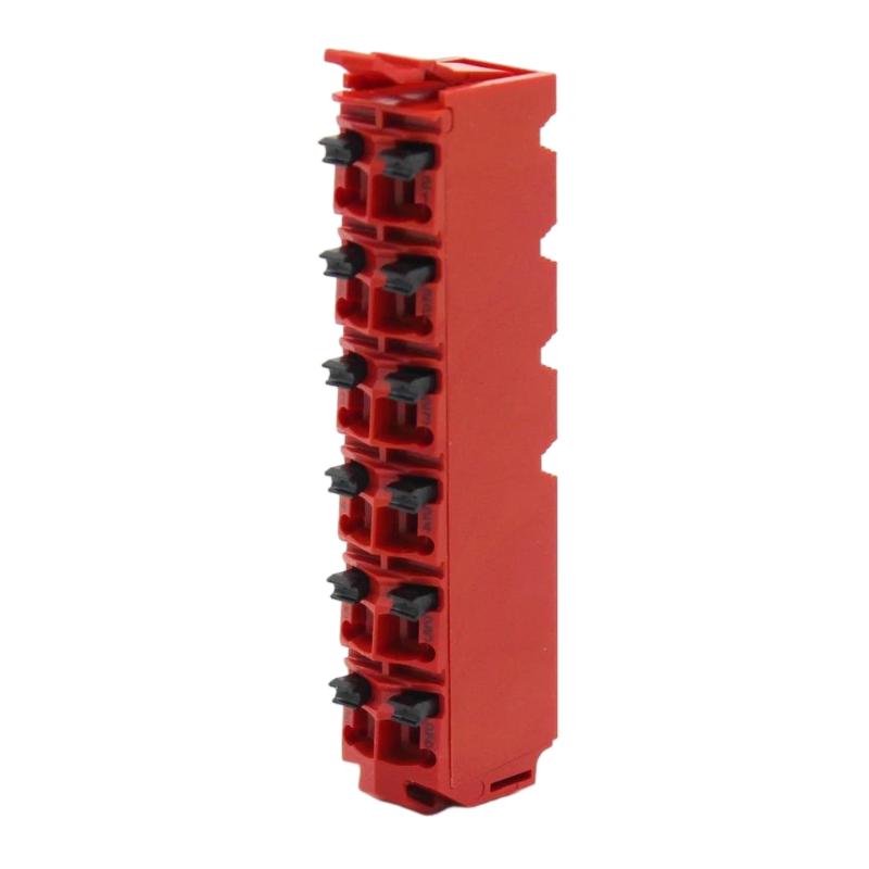
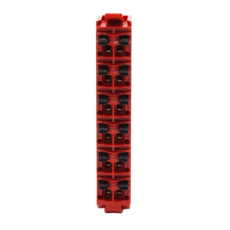
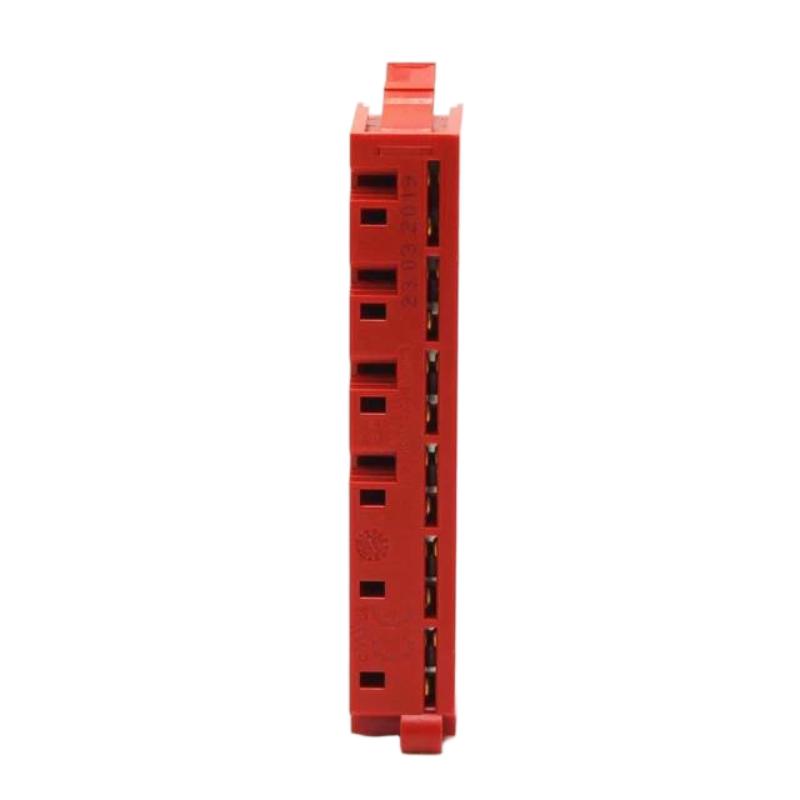
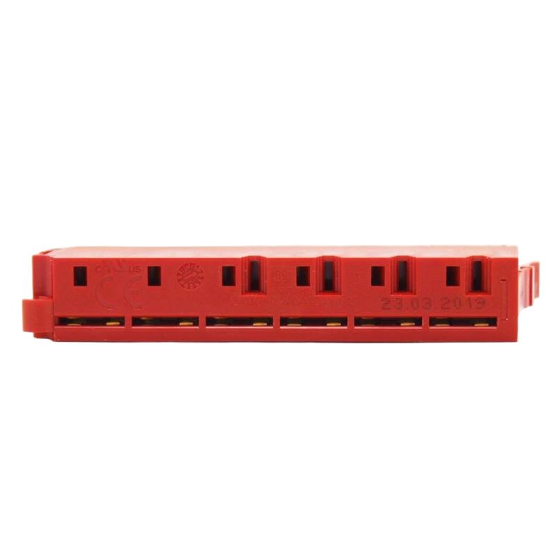
- Schneider
- TM5ACTB52FS
- Safety Encoded Terminal Block
- France
- 95 × 45 × 15 mm
- 0.454 kg
- Xiamen, China
- New & In Stock
- T/T, PayPal, Western Union
- 1 Year
- 1-3 Working Days
- DHL, UPS, TNT, FedEx and EMS.
- 24-Hour Service
- COO
- 16
Our advantage

Global Logistics
We have a 10-year logistics and express cooperation agreement, so our products can be shipped to any place in the world.

Brand new and original
Our products are imported in bulk from the place of origin. Because of the cooperative relationship, our products are all original and 100% new.

24-hour service
We provide 7*24 hours service to our customers. We will be there whenever you need us.

Price advantage
All our products are priced very favorably because we have our own warehouse and supply.
| Company Information | |||
| [email protected] | |||
| Mobile | +8615980777398 | ||
| +8615980777398 | |||
| 15980777398 |
Product Overview
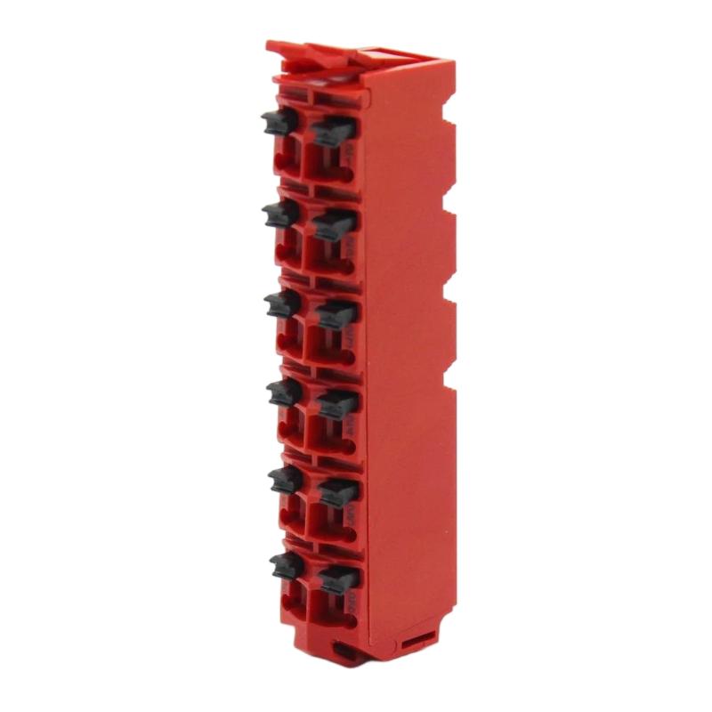
The Schneider Electric TM5ACTB52FS Safety Encoded Terminal Block is identified as a terminal-block component associated with industrial automation and control applications. Terminal blocks provide organized electrical connection points between field wiring, control devices, and compatible automation hardware. In systems involving safety-related equipment, the correct terminal arrangement and approved hardware configuration are particularly important for maintaining reliable signal connections and supporting the intended system design.
Industrial control cabinets commonly contain controllers, I/O modules, sensors, actuators, power supplies, communication equipment, and protective devices. A suitable terminal-block arrangement helps organize conductors, simplify wiring identification, and make inspection and maintenance more manageable. Where a component is designated for safety-related applications, it must be used only within the hardware configuration and operating conditions specified for the associated system.
The Schneider TM5ACTB52FS is supplied with dimensions of 95 × 45 × 15 mm and a weight of approximately 0.454 kg. These physical details are useful for preliminary installation planning, inventory management, and replacement logistics.
The exact electrical function, terminal layout, coding arrangement, and compatibility of this specific part number should be confirmed against the product label and applicable Schneider Electric documentation before installation. The designation alone should not be treated as proof of a particular safety certification or compatibility with every Modicon TM5 system.
Technical Specifications
| Parameter | Specification |
|---|---|
| Manufacturer | Schneider Electric |
| Model | TM5ACTB52FS |
| Product Type | Safety Encoded Terminal Block |
| Product Category | Industrial Automation Connection Component |
| Primary Function | Electrical connection and wiring organization, subject to verified product design |
| Application | Industrial control and compatible automation installations |
| Dimensions | 95 × 45 × 15 mm |
| Weight | 0.454 kg |
| Installation | According to the specified mounting and connection arrangement |
| Electrical Ratings | Verify from the exact product documentation |
| Terminal Configuration | Verify against the product’s terminal diagram |
| Safety Classification | Confirm the applicable certification and approved system configuration |
| Compatibility | Verify using the complete part number and host-system documentation |
The supplied dimensions and weight are retained as provided. Electrical ratings, terminal assignments, coding features, and safety-related specifications require confirmation before the component is selected or installed.
What Is the TM5ACTB52FS?
A terminal block is an electrical connection component that provides a defined interface for connecting conductors within an automation system. Depending on its design, it may support signal wiring, power distribution, field-device connections, or connections to a particular family of control modules.
A terminal block associated with a safety-related automation arrangement may also have specific mechanical coding, identification, or installation requirements intended to help ensure that the correct components are used together. These functions depend on the exact product design and should not be assumed without checking the manufacturer’s specifications.
The TM5ACTB52FS product description identifies it as a safety encoded terminal block. Its practical role should therefore be assessed in the context of the compatible control hardware and the intended installation.
A simplified connection arrangement is:
Field Wiring → Approved Terminal Interface → Compatible Control Hardware → Automation System
The actual electrical path depends on the terminal block’s design. A passive terminal block does not independently perform safety logic unless the product’s verified design explicitly includes active electronic functionality.
Function and Working Principle
1. Electrical Connection
Terminal blocks establish organized connection points for conductors. They help maintain a defined relationship between field wiring and the associated control equipment.
Proper conductor preparation, correct terminal selection, and secure connections are essential for reliable operation. Loose or incorrectly installed conductors may cause intermittent signals, increased electrical resistance, or unexpected equipment behavior.
2. Wiring Organization
A structured terminal arrangement makes it easier to identify individual circuits and trace connections during commissioning and maintenance. Clear identification is particularly valuable in cabinets containing numerous field devices and multiple I/O channels.
The exact terminal numbering and conductor arrangement must follow the approved wiring diagram for the installed hardware.
3. Component Identification and Coding
The supplied product description includes the term “safety encoded.” Where a terminal block incorporates a coding or identification mechanism, that mechanism may help distinguish compatible components or reduce incorrect assembly.
The specific coding method and its purpose for TM5ACTB52FS should be verified from the exact product documentation. Coding or identification features should not be confused with an independent safety function.
4. Integration with Control Hardware
The terminal block may form part of an electrical interface arrangement connecting field conductors to compatible automation equipment. Its suitability depends on the host module, terminal layout, signal type, and installation requirements.
Before connecting any field device, confirm that the terminal block is designed for the intended hardware and that the selected wiring arrangement matches the system drawings.
5. Support for Maintenance
A correctly installed and documented terminal arrangement can simplify circuit inspection, fault tracing, and component replacement. It can also reduce confusion when technicians need to identify individual conductors or verify an input or output circuit.
Role in Industrial Automation and Safety Systems
Industrial automation systems often combine standard control functions with protective measures designed to reduce risks to personnel, machinery, and production processes. Terminal blocks may be part of the wiring infrastructure connecting field devices to control hardware.
In a typical system, field devices provide status signals, control modules process information, and actuators perform the required actions. Safety-related functions must be implemented using appropriately selected and validated hardware, software, wiring, and system architecture.
The terminal block’s role is primarily associated with electrical connection and component integration, subject to its verified design. It should not be considered a substitute for a safety controller, safety relay, certified protective device, or validated safety circuit.
| System Component | Typical Function |
|---|---|
| Field Sensors | Detect equipment or process conditions |
| Push Buttons and Selector Switches | Provide operator commands |
| Protective Devices | Provide protective signals or initiate protective actions |
| Terminal Block | Organizes and connects conductors |
| Compatible I/O Hardware | Acquires or delivers electrical signals |
| PLC or Controller | Executes configured control logic |
| Safety Controller or Relay, Where Required | Performs designated safety functions |
| Actuators and Contactors | Execute control or protective actions |
| HMI | Displays status, alarms, and operating information |
The actual architecture and required components depend on the machine risk assessment, electrical design, and applicable safety requirements.
Industrial Applications
Machine Control Cabinets
Terminal blocks are commonly used in machine-control cabinets to organize connections between field devices and controller hardware. Clear wiring arrangements can improve commissioning efficiency and simplify future maintenance.
Manufacturing Equipment
Automated production equipment may contain numerous sensors, switches, actuators, and control modules. A suitable terminal interface helps maintain orderly connections and supports accurate wiring documentation.
Packaging and Material Handling
Packaging machinery and conveyor systems often require well-organized wiring for position switches, product sensors, operator controls, and equipment feedback. Terminal arrangements must be selected according to the electrical requirements of each circuit.
Industrial Safety-Related Installations
Where a terminal block is approved for a particular safety-related hardware configuration, it may form part of the associated wiring arrangement. Its use must follow the approved design, including component compatibility, wiring rules, and required validation procedures.
The product name alone does not establish a safety integrity level, performance level, or certification. These must be confirmed from the applicable product and system documentation.
Control-System Maintenance and Replacement
Terminal blocks may be replaced during cabinet refurbishment, equipment repair, or scheduled maintenance. Exact identification and careful recording of the existing wiring are important to prevent connection errors.
Installation and System Integration
Correct installation begins with confirming the component’s identity and the requirements of the host system.
Verify the Complete Part Number
Check the product label for the full designation TM5ACTB52FS. Compare it with the existing component, system drawings, bill of materials, and applicable product documentation.
Do not select a replacement solely because it has similar dimensions or belongs to the same manufacturer’s product range.
Confirm Compatibility
Before installation, establish:
- The compatible controller or I/O hardware
- The specified mounting arrangement
- The terminal and connector layout
- The permitted conductor types and sizes
- The relevant electrical ratings
- Any mechanical coding or orientation requirements
- Applicable safety-related installation restrictions
These details should be confirmed for the exact part number and hardware revision.
Isolate the Equipment
Before performing electrical work, follow the site’s approved isolation and lockout procedures. Verify that the relevant circuits are in a safe state before disconnecting conductors or removing components.
Where safety-related circuits are involved, maintenance must be performed by qualified personnel using the prescribed procedures.
Record the Existing Wiring
Before removal, document conductor labels, terminal positions, wire routing, and any relevant module assignments. Photographs and updated wiring records can help reduce errors during replacement.
Do not rely on memory or assume that a similar terminal block uses the same arrangement.
Inspect the Mounting and Connections
Inspect the installation area for damage, contamination, loose hardware, or signs of overheating. Confirm that the terminal block is correctly positioned and secured using the specified method.
Prepare conductors according to the manufacturer’s instructions. Use the required tools and tightening specifications where applicable.
Verify the Completed Installation
Before returning the system to service, check the terminal arrangement against the approved wiring diagram. Confirm that conductors are correctly identified, connections are secure, and no unintended shorts or loose strands are present.
For safety-related applications, complete the required functional checks and validation procedures before the equipment is released for operation.
Troubleshooting the TM5ACTB52FS
Problems associated with a terminal block should be investigated together with the connected wiring and control hardware. A connection component should not automatically be assumed to be the cause of every signal fault.
Intermittent Signal or Equipment Status
Possible causes include loose conductors, damaged cables, vibration, contamination, or an improperly seated component.
Inspect the wiring and mounting arrangement under approved maintenance conditions. Check whether the fault follows a particular conductor, terminal, or connected device.
No Signal Reaches the Control System
A missing signal may result from a disconnected field device, open circuit, incorrect wiring, missing field power, a faulty sensor, or a problem in the associated I/O hardware.
Trace the circuit using the approved schematic. Verify the signal at appropriate test points with suitable instruments and compare the results with the system’s electrical specifications.
Unexpected Circuit Behavior
Unexpected operation can be caused by incorrect terminal assignment, crossed conductors, an incompatible component, or a mismatch between the physical wiring and the controller configuration.
Compare the installed arrangement with the current wiring diagram and hardware records. Do not change wiring assignments without understanding the effect on the control and safety design.
Mechanical Fit or Coding Mismatch
If the component does not fit or mate correctly with the intended hardware, stop the installation. Confirm the complete part number, orientation, hardware family, and applicable coding requirements.
Never force a component into place or modify a coding feature to overcome a compatibility problem.
Suspected Component Damage
Cracks, deformation, damaged contacts, discoloration, or evidence of overheating may indicate that the component requires further inspection or replacement.
Determine the cause of the damage before installing a replacement. Otherwise, the same fault may recur.
Maintenance Recommendations
Regular inspection helps maintain dependable electrical connections and reduces avoidable downtime.
Inspect terminal condition: Look for damaged housings, worn contact areas, deformation, and signs of overheating.
Check conductor security: Verify that wiring remains secure according to the specified connection method and maintenance schedule.
Maintain clear identification: Keep wire labels, terminal references, and cabinet drawings accurate and legible.
Control cabinet conditions: Maintain the environmental conditions specified for the installed equipment and protect the cabinet against contamination and moisture.
Review recurring faults: Document intermittent signals, loose connections, and repeated replacement events to identify underlying causes.
Follow approved safety procedures: Perform inspections and repairs only after the required isolation and risk-control measures have been applied.
Maintenance intervals should reflect the manufacturer’s requirements, operating environment, and the criticality of the installation.
Compatible System Components
The TM5ACTB52FS should be integrated only with hardware confirmed as compatible with its exact product designation. The following table lists general component categories that may be present in an associated automation cabinet; it does not confirm specific model-to-model compatibility.
| Component Category | Purpose |
|---|---|
| Compatible Terminal or Connection Accessories | Provide the specified electrical and mechanical interface |
| PLC or Controller | Executes automation logic |
| I/O Modules | Connect field signals with the controller |
| Field Sensors and Switches | Provide status and process signals |
| Protective Devices | Support the intended protection design |
| Safety Controller or Relay, Where Required | Implements designated safety functions |
| Industrial Power Supply | Provides appropriately rated electrical power |
| Terminal Labels and Wiring Accessories | Support circuit identification and maintenance |
| HMI or Operator Panel | Presents system status and alarms |
Before selecting any associated component, verify the required hardware family, electrical characteristics, mechanical interface, and approved system configuration.
Replacement and Procurement Considerations
When purchasing a replacement Schneider Electric TM5ACTB52FS, verify the complete part number and compare it with the original component and installed hardware.
Important considerations include:
- Exact product designation
- Manufacturer identification and hardware revision
- Terminal configuration and mechanical interface
- Compatibility with the host equipment
- Electrical ratings and conductor requirements
- Coding or orientation requirements
- Product condition and storage history
- Required commissioning and validation procedures
The supplied dimensions of 95 × 45 × 15 mm and weight of 0.454 kg can assist with inventory planning, packaging, and preliminary space assessment. Physical measurements alone cannot establish interchangeability.
For replacement work, preserve the existing wiring records and confirm the intended circuit function before disconnecting the original part. After installation, perform all required electrical checks and, where applicable, safety-system validation.
Key Advantages
Organized Electrical Connections
A suitable terminal block helps keep conductors arranged and identifiable, supporting more efficient cabinet assembly and maintenance.
Simplified Fault Tracing
Clear terminal assignments and wiring documentation make it easier to trace circuits and investigate signal problems.
Support for Structured Automation Installations
Correctly selected connection hardware helps integrate field wiring with compatible control equipment.
Compact Physical Dimensions
The listed dimensions of 95 × 45 × 15 mm provide useful information for preliminary cabinet-layout and inventory planning.
Better Maintenance Documentation
Consistent labeling and accurate wiring records support repeatable installation, inspection, and replacement procedures.
These benefits depend on using the correct component in the intended application and following the relevant installation requirements.
Technical FAQs
What is the Schneider TM5ACTB52FS?
It is identified by the supplied product description as a Schneider Electric Safety Encoded Terminal Block. Its exact connection function and compatibility should be verified using the complete part number.
What are its dimensions?
The supplied dimensions are 95 × 45 × 15 mm.
How much does the TM5ACTB52FS weigh?
The supplied weight is approximately 0.454 kg.
Does this terminal block perform safety logic?
A terminal block generally provides an electrical connection interface rather than executing safety logic. The exact functionality of this model must be confirmed, and safety functions must rely on the appropriately specified and validated system architecture.
Is it compatible with every Schneider Electric PLC?
No. Compatibility depends on the exact hardware family, mechanical interface, electrical requirements, and product documentation. The manufacturer name alone does not establish compatibility.
What should be checked before replacing the terminal block?
Verify the complete part number, terminal arrangement, mechanical interface, wiring diagram, host hardware, and any applicable coding or safety requirements.
What can cause intermittent connections?
Common possibilities include loose conductors, damaged wiring, vibration, contamination, incorrect installation, or damage to the connection interface.
Can a similar-looking terminal block be used as a substitute?
Not without confirming compatibility. Similar dimensions and appearance do not establish equivalent electrical characteristics, mechanical fit, coding, or safety suitability.
Conclusion
The Schneider Electric TM5ACTB52FS Safety Encoded Terminal Block is identified as an industrial connection component intended for use in a compatible automation installation. Terminal-block hardware supports organized electrical wiring, consistent circuit identification, and maintainable connections between field conductors and control equipment.
With supplied dimensions of 95 × 45 × 15 mm and a weight of 0.454 kg, the component’s physical characteristics can support preliminary cabinet planning and replacement logistics. Reliable use depends on verifying the exact product identity, terminal arrangement, host-system compatibility, and installation requirements.
For procurement, maintenance, and replacement, confirm the complete TM5ACTB52FS designation before installation. Careful wiring documentation, secure connections, appropriate electrical isolation, and required functional validation help maintain dependable operation in industrial automation systems.