

ProductPRODUCT
Featured products



Contact Us
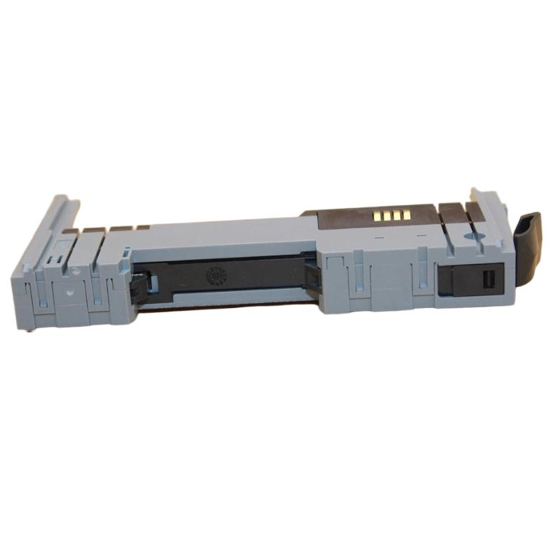
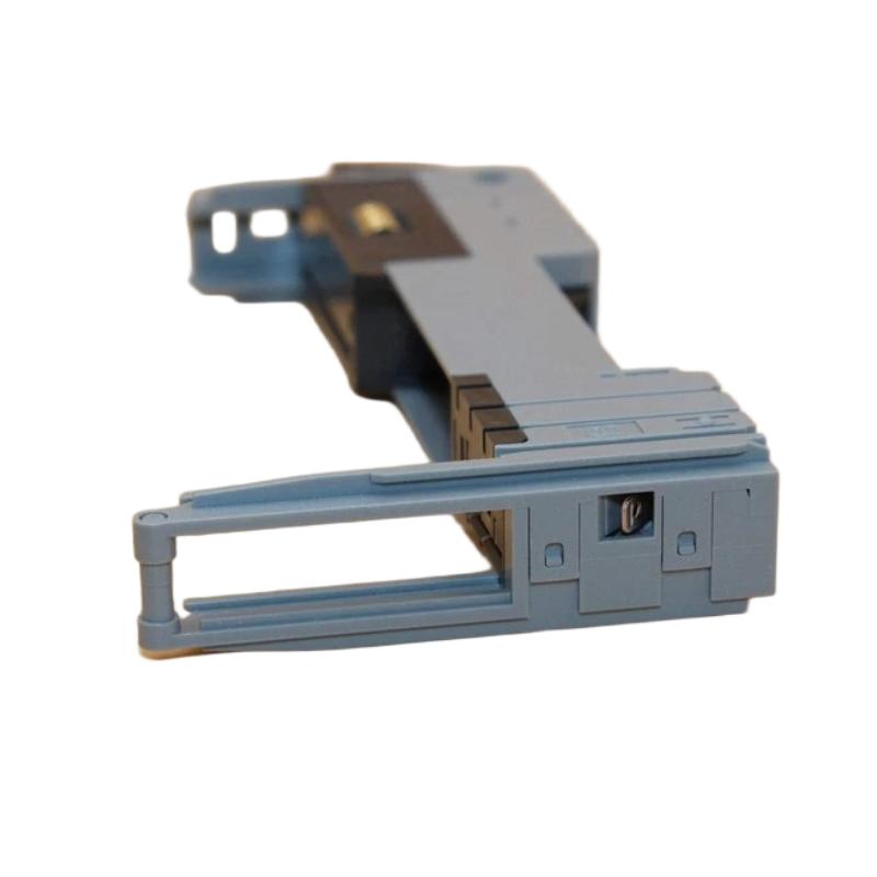
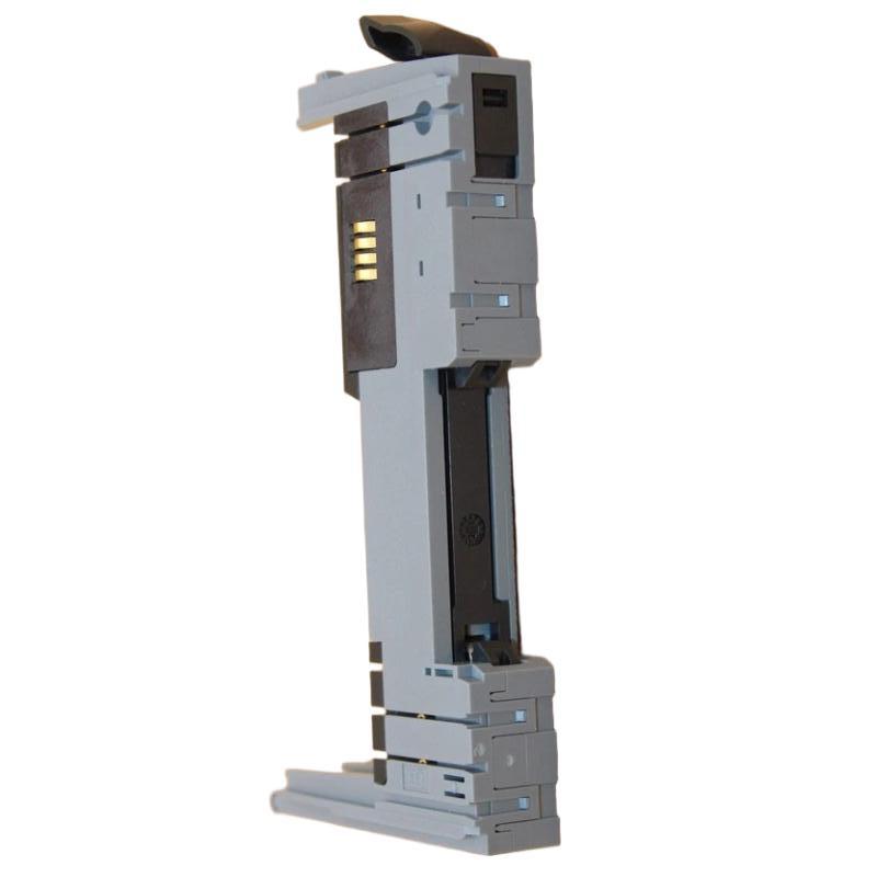
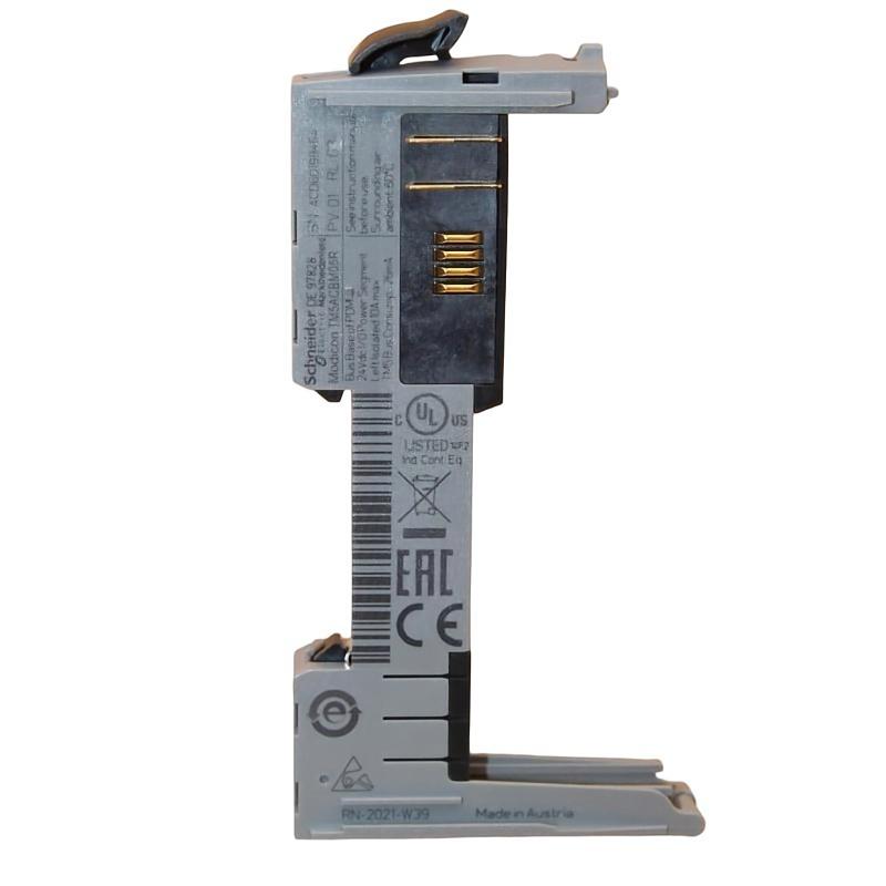
- Schneider
- TM5ACBM05R
- Addressable Bus Base
- France
- 25 × 73.5 × 90 mm
- 0.02 kg
- Xiamen, China
- New & In Stock
- T/T, PayPal, Western Union
- 1 Year
- 1-3 Working Days
- DHL, UPS, TNT, FedEx and EMS.
- 24-Hour Service
- COO
- 21
Our advantage

Global Logistics
We have a 10-year logistics and express cooperation agreement, so our products can be shipped to any place in the world.

Brand new and original
Our products are imported in bulk from the place of origin. Because of the cooperative relationship, our products are all original and 100% new.

24-hour service
We provide 7*24 hours service to our customers. We will be there whenever you need us.

Price advantage
All our products are priced very favorably because we have our own warehouse and supply.
| Company Information | |||
| [email protected] | |||
| Mobile | +8615980777398 | ||
| +8615980777398 | |||
| 15980777398 |
Product Overview
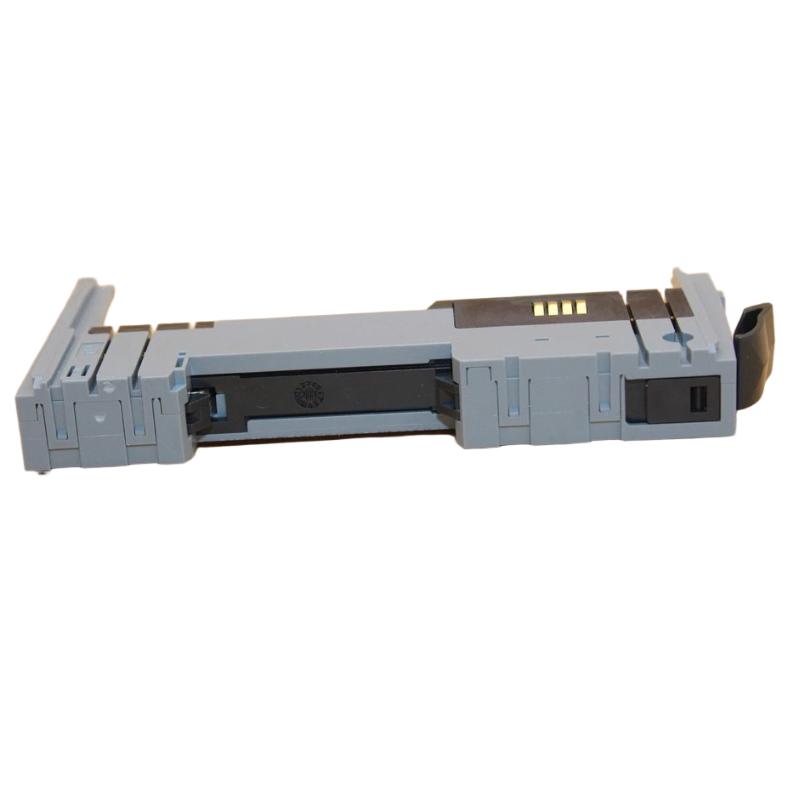
The Schneider Electric TM5ACBM05R Addressable Bus Base is an industrial automation hardware component designed for use within a compatible modular control system. A bus base provides a mechanical and electrical interface between supported automation modules and the system’s internal communication and interconnection structure. It helps establish the connections required for modules to exchange signals and operate as part of a coordinated control architecture.
In modular automation systems, individual components perform different functions, including digital signal acquisition, analog measurement, output control, and communication. The bus base forms part of the physical infrastructure that allows compatible modules to be assembled into an organized system. Correct selection and installation are important because mechanical compatibility alone does not guarantee that a base is electrically or functionally suitable for a particular module.
The TM5ACBM05R is identified by the supplied product description as an addressable bus base associated with Schneider Electric automation hardware. Its compact dimensions of 25 × 73.5 × 90 mm and listed weight of 0.02 kg make it suitable for applications where compact modular construction is required, provided the installed system meets the product’s mounting and environmental requirements.
Before integrating or replacing this component, verify the complete reference, supported module family, connection arrangement, and applicable system documentation. These checks help prevent incorrect installation and ensure that the bus base matches the intended controller architecture.
Technical Specifications
| Parameter | Specification |
|---|---|
| Manufacturer | Schneider Electric |
| Model | TM5ACBM05R |
| Product Type | Addressable Bus Base |
| Product Category | Modular Automation Hardware |
| Primary Function | Module mounting and system interconnection, subject to exact product verification |
| Product Family | Verify the applicable Schneider Electric hardware family |
| Communication Role | Depends on the supported module and system architecture |
| Dimensions | 25 × 73.5 × 90 mm |
| Weight | 0.02 kg |
| Installation | Compatible mounting arrangement; verify the product documentation |
| Typical Application | Modular industrial automation systems |
| Compatibility | Confirm the supported controller, module type, and bus arrangement before installation |
The table includes the supplied product identification and physical measurements. Detailed electrical specifications, connector assignments, supported module combinations, and bus-system requirements should be verified against the exact TM5ACBM05R reference.
What Is the Schneider TM5ACBM05R?
An addressable bus base is a hardware component used within certain modular automation architectures to support module installation and interconnection. Depending on the system design, the base may provide mechanical positioning, electrical contacts, or connections associated with the module’s internal bus.
The bus structure allows compatible modules to form part of a larger control system. For example, a controller may exchange data with input and output modules so that information from field devices can be processed and control commands can be delivered to the relevant equipment.
The bus base itself should not be confused with a complete PLC, an independent communication gateway, or a general-purpose network switch. Its function depends on the specific hardware architecture in which it is installed.
A simplified modular control arrangement can be represented as:
Controller → Compatible Bus Structure → Supported Automation Modules → Field Devices
The actual arrangement, electrical interface, and module compatibility depend on the verified product design.
Function and Working Principle
1. Mechanical Module Support
A bus base provides a designated mounting interface for the modules intended to use it. Proper positioning helps maintain the required alignment between the module and its associated connections.
Correct mechanical installation is important in compact control cabinets, where multiple modules may be installed close together. A mismatched base can prevent proper seating or place unnecessary stress on connectors.
2. Electrical Interconnection
Where the product design includes electrical bus contacts, the base contributes to the connection between supported hardware components. These connections may carry signals or other electrical interfaces required by the host system.
The exact contact arrangement and electrical role must be confirmed from the product documentation. The base should not be assumed to support arbitrary modules simply because the connectors appear similar.
3. Addressing and Module Organization
In an addressable modular system, the control architecture must identify the installed hardware correctly. Depending on the design, addressing may be established through hardware configuration, module identification, or other system-specific mechanisms.
The bus base should not be assumed to perform independent address assignment unless that function is explicitly specified for the exact model. Correct system recognition depends on the complete hardware arrangement and its configuration.
4. Integration with the Automation System
When installed in a compatible configuration, the bus base forms part of the physical infrastructure supporting communication and data exchange among the intended modules.
The controller and associated modules perform the actual automation tasks. The bus base provides the required hardware interface rather than independently executing control logic.
5. Support for Modular Maintenance
Modular construction can make it easier to organize equipment, identify components, and carry out maintenance. A correctly selected base helps preserve the intended module arrangement and connection integrity during installation or replacement.
Any removal or replacement procedure must follow the requirements of the host system, including power isolation and restrictions on live module changes.
Role in Industrial Control Systems
Industrial automation systems are commonly built from interconnected components that perform sensing, processing, communication, and control. A bus base can contribute to the physical organization and interconnection of these components.
In a typical modular architecture, field sensors provide process information, input modules acquire signals, a controller evaluates the control logic, and output modules communicate commands to actuators or interface devices. The bus base supports the compatible hardware arrangement through which the modules are installed and interconnected.
| System Component | Typical Function |
|---|---|
| PLC or Automation Controller | Executes the control program |
| Bus Base | Provides the specified mounting and interconnection interface |
| Digital Input Module | Acquires discrete signals from compatible field devices |
| Analog Input Module | Acquires continuous process measurements |
| Digital Output Module | Provides discrete control signals |
| Analog Output Module | Provides variable output signals where supported |
| Industrial Power Supply | Supplies appropriately rated electrical power |
| Terminal Blocks | Organize field wiring |
| HMI Panel | Displays operating conditions and alarms |
| Engineering Software | Supports hardware configuration and diagnostics |
The components listed above represent common functional roles in automation systems. They should not be interpreted as a verified list of directly compatible products for the TM5ACBM05R. Compatibility must be established from the exact hardware specifications.
Industrial Applications
Modular Machine Control
Modular automation hardware is used in manufacturing equipment that requires organized controller, input, output, and communication components. A suitable bus base can support the installation of compatible modules within the machine’s control cabinet.
Packaging Equipment
Packaging machines frequently use modular control hardware to coordinate sensors, actuators, operator commands, and production sequences. Proper module interconnection helps maintain an organized control architecture.
Material Handling Systems
Conveyors and material handling equipment may use modular PLC systems to monitor product positions, control drive interfaces, and coordinate transfer operations. Bus hardware forms part of the physical arrangement where the selected platform uses a modular structure.
Production-Line Automation
Production lines often require multiple modules to support different signal types and machine functions. A compatible bus base can help maintain the intended module arrangement and interconnection within a distributed control panel.
Process Equipment
Industrial process equipment may combine discrete monitoring, analog measurement, and control outputs. Modular hardware provides a structured way to organize these functions, subject to the requirements of the chosen control platform.
Control Cabinet Assembly
Compact components are valuable when panel space is limited. The TM5ACBM05R’s listed dimensions of 25 × 73.5 × 90 mm can assist preliminary layout planning, although the full assembly must also account for module dimensions, wiring clearance, mounting hardware, and ventilation.
Installation and System Integration
Correct installation begins with confirming that the bus base is suitable for the intended hardware configuration.
Verify the Product Reference
Check the complete model number TM5ACBM05R against the component label and system documentation. Confirm the exact product designation, revision where applicable, and supported hardware family.
Do not select a replacement solely by appearance or physical dimensions. Similar-looking bases may have different connection arrangements or intended uses.
Confirm Module Compatibility
Before mounting the component, identify the modules that will be installed with it. Check the supported combinations, mechanical interface, electrical connection requirements, and the system’s hardware configuration rules.
If compatibility cannot be confirmed, do not force the component into the assembly or attempt to modify connectors to make it fit.
Prepare the Installation Area
Ensure that the control cabinet is suitable for the equipment and meets the applicable environmental requirements. Provide enough clearance for installation, wiring, inspection, and maintenance.
Check that the mounting surface or rail arrangement matches the product’s specified installation method. The dimensions of the bus base alone do not establish the complete space requirements of the assembled system.
Install the Base Correctly
Follow the applicable mounting instructions and ensure that the component is seated and secured as specified. Avoid excessive mechanical force, which may damage the housing or connection interfaces.
Inspect the component for cracks, damaged contacts, deformation, contamination, or other conditions that could compromise installation.
Connect the Associated Hardware
Install only the modules specified as compatible. Confirm connector alignment and ensure that the modules are fully seated according to the approved assembly procedure.
Where electrical connections are present, check the designated connection points and system wiring requirements before applying power.
Configure and Verify the System
After installation, inspect the complete hardware arrangement and confirm that the controller recognizes the intended configuration where applicable. Review available diagnostic information and verify that the installed modules operate as expected.
Record the final component reference, module arrangement, and relevant configuration details for future maintenance.
Troubleshooting the TM5ACBM05R
Problems involving a bus base should be investigated as part of the complete modular assembly. A system fault may originate from a module, connector, power supply, configuration, or wiring issue rather than the base itself.
Module Not Recognized
If the controller does not recognize an installed module, check:
- Whether the exact base and module combination is supported
- Whether the module is correctly seated
- Whether the connection interface is damaged or contaminated
- Whether the controller hardware configuration matches the physical installation
- Whether the required system power is available
- Whether diagnostic messages identify a configuration or hardware fault
Confirm the supported configuration before replacing the base.
Intermittent Communication or Data Errors
Intermittent data problems may be associated with loose connections, damaged contacts, an incompatible module arrangement, unstable power, electrical interference, or a fault elsewhere in the system.
Inspect the assembly under the approved maintenance procedure and review controller diagnostics. If the platform provides module-status indicators, use them to help identify the affected component.
Module Does Not Seat Properly
Difficulty installing a module may indicate incorrect component selection, connector misalignment, damaged mechanical features, contamination, or an improper mounting arrangement.
Do not force the module into place. Compare the component references and mechanical interfaces, and replace damaged parts with correctly specified components.
Repeated Hardware Faults After Replacement
If a fault remains after replacing the bus base, investigate the other parts of the hardware chain. The cause may be an incompatible module, incorrect configuration, damaged wiring, insufficient power, or a defective controller interface.
Record the fault details before making further changes. Repeatedly replacing components without verifying the complete configuration can increase downtime and may introduce additional problems.
Maintenance Recommendations
Regular inspection helps maintain reliable mechanical and electrical connections within modular automation equipment.
Inspect the housing: Look for cracks, deformation, broken retaining features, or signs of mechanical stress.
Check connection interfaces: Inspect contacts and connectors for contamination, corrosion, or visible damage. Use only approved cleaning methods.
Verify module seating: Confirm that the installed modules are correctly positioned and secured according to the system’s assembly instructions.
Maintain cabinet conditions: Keep the equipment within the specified environmental limits and protect the assembly from excessive dust, moisture, vibration, and heat.
Review system diagnostics: Record recurring module-recognition or communication faults and investigate their root causes.
Keep configuration records current: Document replacement parts, module positions, and hardware configuration changes.
Follow safe maintenance procedures: Isolate power where required and observe applicable electrostatic-discharge precautions before handling electronic components. Do not assume that live replacement is permitted unless the system explicitly supports it.
Compatible System Components
The TM5ACBM05R should be integrated only with components confirmed to be compatible with its exact product design. The following table identifies common categories that may appear in a modular automation installation.
| Component Category | Purpose |
|---|---|
| Compatible Controller | Executes automation logic and manages the supported hardware configuration |
| Supported Bus-Compatible Modules | Provide the input, output, or other functions required by the system |
| Digital Input Modules | Acquire discrete signals from field devices |
| Analog Input Modules | Acquire supported continuous measurements |
| Digital Output Modules | Deliver discrete control signals |
| Analog Output Modules | Provide supported variable control signals |
| Power Supply | Provides the required electrical supply |
| Terminal Blocks and Wiring Accessories | Organize electrical connections |
| HMI or Operator Panel | Provides monitoring and operator interaction |
| Engineering Software | Supports configuration, diagnostics, and maintenance |
This is a functional overview, not a guarantee of direct compatibility with every product category listed. Confirm exact model compatibility and system requirements before purchasing or installing associated components.
Replacement and Procurement Considerations
When sourcing a replacement for the Schneider Electric TM5ACBM05R Addressable Bus Base, exact identification is essential.
Before ordering, confirm:
- Complete model number
- Product designation and hardware revision, where applicable
- Supported module family
- Mechanical mounting arrangement
- Electrical connection and bus interface
- Required accessories
- Condition of the existing assembly
- Compatibility with the installed controller and modules
The supplied dimensions are 25 × 73.5 × 90 mm, and the listed weight is 0.02 kg. These values are useful for inventory records and preliminary packaging or cabinet-layout planning.
For maintenance replacements, compare the original component’s label and connection arrangement with the proposed replacement. A component from the same manufacturer is not necessarily interchangeable, and a similar physical shape does not confirm electrical compatibility.
Key Advantages
Compact Construction
The listed dimensions of 25 × 73.5 × 90 mm support compact hardware planning for suitable modular control installations.
Modular System Organization
A correctly selected bus base helps maintain the intended mechanical arrangement and interconnection of compatible automation components.
Support for Structured Maintenance
Clearly identified modular components make it easier to document hardware layouts, inspect connections, and trace potential system faults.
Integration into Industrial Control Architectures
When used in its intended configuration, the bus base contributes to the physical infrastructure of a modular automation system.
Lightweight Design
With a listed weight of 0.02 kg, the component is lightweight for handling and inventory purposes. Its actual installation requirements must still be determined from the product documentation.
Technical FAQs
What is the Schneider TM5ACBM05R?
The TM5ACBM05R is identified by the supplied description as an addressable bus base for industrial automation hardware. Its exact function and supported module combinations should be confirmed against the product documentation.
What is the primary function of a bus base?
A bus base generally provides the specified mounting and interconnection interface for compatible modules. The exact electrical and communication functions depend on the hardware architecture.
What are the dimensions of the TM5ACBM05R?
The supplied dimensions are 25 × 73.5 × 90 mm.
How much does the TM5ACBM05R weigh?
The supplied weight is 0.02 kg.
Can the TM5ACBM05R be used with any Schneider Electric PLC?
No. Compatibility depends on the exact product family, supported module arrangement, electrical interface, and controller requirements. The complete reference should be checked before installation.
Is the bus base itself a PLC or communication gateway?
It should not be treated as a standalone PLC or network gateway based solely on its product description. Its role is associated with the supported modular hardware architecture.
What should be checked if a module is not recognized?
Check the exact hardware combination, module seating, connection condition, system power, hardware configuration, and available diagnostics. Confirm that the base and module are supported together before replacing components.
Can a similar bus base be used as a replacement?
Not without verification. The replacement must match the required mechanical interface, electrical connections, module compatibility, and system requirements.
Conclusion
The Schneider Electric TM5ACBM05R Addressable Bus Base is described as a modular automation hardware component intended to support the installation and interconnection of compatible system modules. In a suitable control architecture, this type of component contributes to an organized hardware arrangement and helps establish the connections required by the intended automation system.
With supplied dimensions of 25 × 73.5 × 90 mm and a listed weight of 0.02 kg, the TM5ACBM05R has a compact physical profile for appropriate industrial installations. Reliable integration depends on confirming the exact product identity, supported modules, mounting requirements, connection arrangement, and controller configuration.
For installation, maintenance, or replacement, verify the complete model reference and applicable hardware requirements before proceeding. Correct component matching, careful assembly, and documented commissioning help preserve system reliability and reduce avoidable maintenance downtime.