

ProductPRODUCT
Featured products



Contact Us
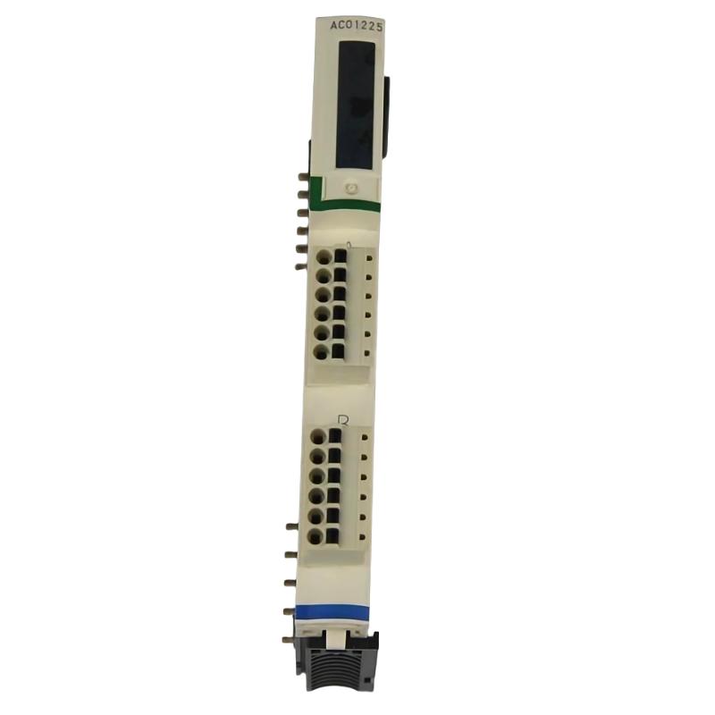
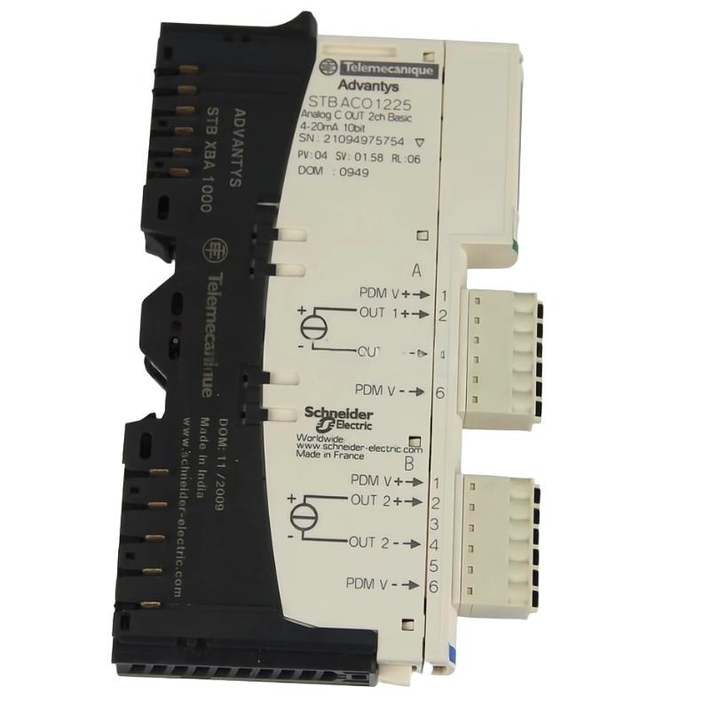
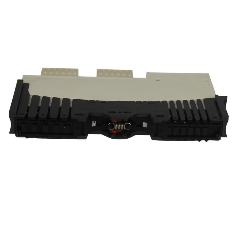
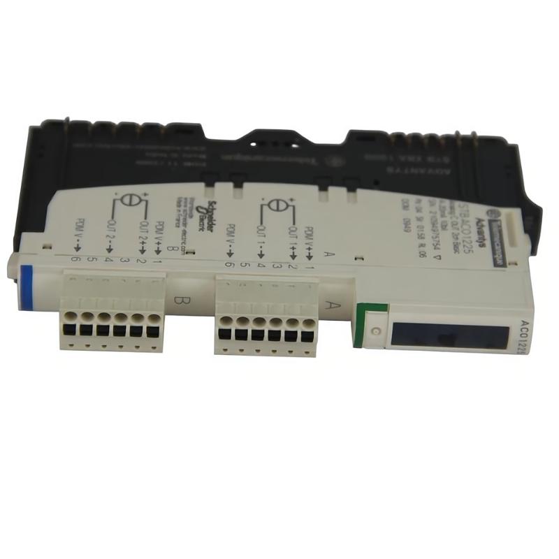
- Schneider
- STBACO1225K
- Basic Analog Output Kit
- France
- 13.9 x 128.3 x 70 mm
- 0.082 kg
- Xiamen, China
- New & In Stock
- T/T, PayPal, Western Union
- 1 Year
- 1-3 Working Days
- DHL, UPS, TNT, FedEx and EMS.
- 24-Hour Service
- COO
- 14
Our advantage

Global Logistics
We have a 10-year logistics and express cooperation agreement, so our products can be shipped to any place in the world.

Brand new and original
Our products are imported in bulk from the place of origin. Because of the cooperative relationship, our products are all original and 100% new.

24-hour service
We provide 7*24 hours service to our customers. We will be there whenever you need us.

Price advantage
All our products are priced very favorably because we have our own warehouse and supply.
| Company Information | |||
| [email protected] | |||
| Mobile | +8615980777398 | ||
| +8615980777398 | |||
| 15980777398 |
Product Overview
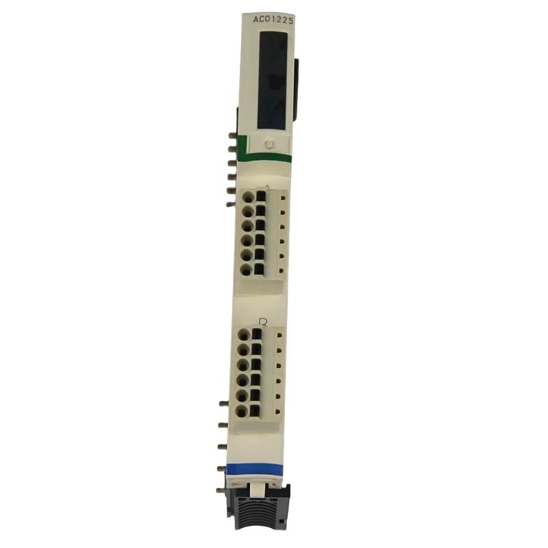
The Schneider Electric STBACO1225K Basic Analog Output Kit is an industrial automation component identified for analog output applications within compatible Schneider Electric control systems. Analog output interfaces allow a controller to send variable electrical signals to field devices, enabling continuous adjustment of process variables such as speed, position, pressure, flow, and temperature when used with appropriate control equipment.
Unlike digital outputs, which generally represent ON/OFF states, analog outputs provide a varying signal corresponding to a commanded value. Depending on the hardware configuration, analog signals can be used by compatible variable speed drives, control valves, actuator interfaces, and other industrial devices that require a proportional reference or command signal.
The STBACO1225K designation is associated with Schneider Electric’s Advantys STB product family. The supplied product description identifies it as a basic analog output kit. Before installation, the exact kit contents, supported output signal types, channel configuration, and compatibility with the intended STB island should be confirmed against the applicable product documentation.
With listed dimensions of 13.9 × 128.3 × 70 mm and a weight of approximately 0.082 kg, the component has a compact physical profile suitable for applications where control-system space and organized module integration are important.
Technical Specifications
| Parameter | Specification |
|---|---|
| Manufacturer | Schneider Electric |
| Model / Part Number | STBACO1225K |
| Product Type | Basic Analog Output Kit |
| Product Family | Advantys STB, subject to exact product verification |
| Primary Function | Analog output interface or associated output kit |
| Signal Type | Analog output; exact signal format requires verification |
| Channel Configuration | Confirm from the exact product documentation |
| System Role | Transfers controller commands to compatible field interfaces |
| Dimensions | 13.9 × 128.3 × 70 mm |
| Weight | 0.082 kg |
| Installation | Compatible system mounting arrangement; verify before installation |
| Typical Applications | Industrial process control and automated equipment |
| Compatibility | Confirm against the host STB island, output module, and system configuration |
The physical specifications above are based on the supplied product information. Specific electrical ratings, supported current or voltage ranges, channel count, accuracy, resolution, isolation, and kit contents should be verified before the product is selected or commissioned.
What Is the Schneider STBACO1225K?
The STBACO1225K is identified as a basic analog output kit for industrial automation use. Analog output functionality is important in control systems where a device must receive a continuously adjustable command rather than a simple switching signal.
For example, a controller may need to provide a reference signal to a compatible drive to regulate motor speed, or send a proportional command to a suitable valve-positioning interface. The analog output system converts the controller’s requested value into an electrical signal that the receiving equipment can interpret.
A typical signal path is:
PLC or Controller → Output Configuration → Analog Output Interface → Field Device → Process Response
The exact role of the STBACO1225K within this path depends on its verified product identity and the hardware with which it is supplied. The kit should not be assumed to function as a standalone analog output module without confirming its contents and installation requirements.
Function and Working Principle
1. Controller Command Generation
An automation controller calculates a desired operating value based on the control program, operator commands, sensor feedback, or process requirements.
Examples include a requested motor speed, a valve position, or a setpoint for compatible process equipment.
2. Analog Signal Generation
The analog output hardware converts the configured command into an appropriate electrical signal. The signal may be voltage-based or current-based, depending on the specific hardware.
The supported signal type and operating range must match the receiving device. These details should be confirmed from the exact module or kit specifications rather than inferred from the product name.
3. Signal Transfer to Field Equipment
The output signal is transferred through the appropriate terminals and field wiring to the receiving equipment. Correct polarity, terminal assignment, cable selection, grounding, and electrical isolation are important for reliable operation.
4. Field Device Response
A compatible receiving device interprets the analog command and adjusts its operating condition. For example, a suitable drive may change a speed reference, while a compatible actuator interface may adjust a valve position.
The analog output provides the command signal; the actual mechanical or process response depends on the connected equipment.
5. Process Regulation
When analog output commands are combined with suitable sensor feedback and controller logic, they can form part of a closed-loop control strategy. The controller compares the measured process value with the desired setpoint and adjusts its output accordingly.
The performance of this arrangement depends on the complete control loop, including the sensors, controller configuration, output hardware, and final control element.
Role in Industrial Control Systems
Analog output functionality helps connect digital control logic with industrial equipment that requires proportional adjustment. Within a compatible automation architecture, the STBACO1225K may support the associated output-interface arrangement, subject to verification of its exact role.
Typical system functions include:
- Transmitting variable control commands
- Supporting proportional process regulation
- Providing reference signals to compatible equipment
- Integrating output commands into automated sequences
- Supporting centralized process control
- Enabling coordination between the controller and field devices
The overall control architecture may include PLCs, distributed I/O, analog output modules, drives, valve interfaces, operator panels, and industrial communication infrastructure.
The STBACO1225K’s precise position in that architecture should be confirmed before it is used in a new design or replacement project.
Industrial Applications
Process Automation
Analog output interfaces are commonly used where a process variable must be adjusted gradually. In suitable systems, the output command can regulate compatible equipment according to a controller’s process logic.
Pumping Systems
A compatible analog output arrangement may transmit a speed reference to a variable speed drive controlling a pump motor. The resulting flow or pressure depends on the pump, drive, process conditions, and feedback strategy.
HVAC and Building Services
Industrial and building automation systems may use analog commands to regulate compatible dampers, valve actuators, and other modulating equipment. The output signal must match the receiving device’s electrical requirements.
Manufacturing Equipment
Automated production systems sometimes require proportional adjustment of motor speed, actuator position, or other machine operating parameters. Analog output interfaces can provide the command signal where supported by the controller and field device.
Water and Wastewater Treatment
Suitable control systems can use analog output commands to regulate compatible dosing equipment, drives, and process-control devices. The complete installation must be designed around the required signal type and operating range.
General Industrial Process Control
Analog output functionality can be useful in applications where digital switching alone is insufficient, including systems that require continuously variable commands or setpoint adjustment.
These examples describe general analog-output applications. They do not establish that every application or receiving device is directly compatible with the STBACO1225K.
Installation and System Integration
Correct installation begins with confirming whether the STBACO1225K is a complete functional module, a mounting or connection kit, or another associated component within the relevant product family.
Confirm the Product Identity
Check the complete part number, product label, revision information, and supplied contents. Compare these details with the installed hardware and the intended system configuration.
Do not substitute a similarly named component solely because it belongs to the same manufacturer or product family.
Verify the Host System
Confirm that the intended Advantys STB island or other host architecture supports the identified component. Check the required base, module, terminal arrangement, power arrangement, and any applicable configuration restrictions.
Compatibility should be established from the exact part number and system design rather than physical dimensions alone.
Check Electrical Requirements
Before wiring, establish the supported output signal type and range, terminal assignment, output loading limits, and isolation requirements.
Also verify that the receiving device accepts the same signal type and range. An output configured for one electrical interface may not operate correctly with a device designed for another.
Prepare the Installation
Follow the applicable mounting and electrical installation procedures. Maintain appropriate clearance, cable routing, environmental protection, and access for inspection.
Keep analog signal wiring appropriately separated from high-power conductors where required by the system design. Correct grounding and shielding practices can help reduce electrical interference.
Configure the Controller and Output Channel
Where the component is part of a configurable output system, verify the hardware configuration and assign the required output address or channel according to the engineering design.
Check the selected output range, scaling, and commanded-value limits. Incorrect scaling can result in a field device receiving an unintended command even when the electrical signal is present.
Commission the Output
After installation, test the output using approved commissioning procedures and suitable measuring equipment. Confirm that the controller’s command produces the expected signal and that the receiving device responds correctly.
Document the normal operating range, scaling, signal destination, and expected field-device response.
Troubleshooting the STBACO1225K Analog Output Arrangement
When an analog output system fails to respond as expected, inspect the complete signal path before replacing hardware.
No Output Signal
Potential causes include incorrect installation, a missing system supply, configuration errors, wiring problems, an incompatible receiving device, or a fault in the associated output hardware.
Check the product identity and installation arrangement first. Then inspect the relevant system diagnostics, terminal connections, and output configuration.
Output Signal Is Incorrect
An incorrect output may result from unsuitable scaling, a mismatched signal range, an incorrect channel assignment, wiring errors, or a problem with the receiving device.
Compare the commanded value with the expected electrical signal. Verify the configured range and engineering-unit scaling before assuming that the hardware is defective.
Output Signal Is Unstable
Possible causes include electrical interference, loose connections, poor grounding, unsuitable cable routing, unstable supply conditions, or an issue in the receiving device.
Inspect the wiring and installation environment. If the problem occurs only when nearby equipment operates, investigate electromagnetic interference and cable separation.
Field Device Does Not Respond
If the output signal appears correct but the field device does not respond, verify that the receiving equipment supports the same signal format and range. Check its input configuration, operating mode, power supply, and fault indications.
The problem may be downstream of the analog output interface rather than within the kit itself.
Configuration or Hardware Fault
If the controller reports a hardware or configuration error, confirm the exact product identification, the selected hardware entry, the island arrangement, and any required associated components.
Record diagnostic information before changing the configuration. Follow the prescribed isolation and electrostatic-discharge procedures when inspecting or replacing electronic components.
Maintenance Recommendations
Regular maintenance helps support reliable analog signal transmission and reduces avoidable commissioning problems.
Inspect connections: Check terminals, connectors, and field wiring for looseness, corrosion, damage, or signs of overheating.
Review configuration: Keep hardware selections, channel assignments, output scaling, and field-device ranges documented.
Monitor signal behavior: Investigate persistent deviations, unexpected output changes, and recurring diagnostic messages.
Control electrical interference: Maintain appropriate grounding and cable routing practices according to the system design.
Maintain the cabinet environment: Keep equipment within the specified environmental limits and protect it from excessive dust, moisture, and vibration.
Verify after replacement: When a component is changed, repeat the relevant signal checks and confirm that the receiving equipment responds as intended.
Maintenance should follow the requirements of the complete installed system, including the associated output module and any connected field device.
Compatible System Components
The STBACO1225K should be matched to the correct hardware architecture and associated components. The following table describes typical component roles in an industrial analog-output system; it is not a guarantee of compatibility with every model listed in these categories.
| Component Type | Typical Function |
|---|---|
| Compatible PLC or Controller | Generates the required control commands |
| Compatible Analog Output Module | Produces the specified analog signal |
| STB System Base or Mounting Hardware | Supports the applicable module installation |
| Terminal or Connection Components | Provides the required electrical connections |
| Industrial Power Supply | Supplies the specified system power |
| Variable Speed Drive | Receives a compatible reference signal where supported |
| Modulating Valve or Actuator Interface | Uses a suitable command signal to regulate position |
| HMI Panel | Provides operator setpoint entry and status display |
| Engineering Software | Supports hardware configuration and diagnostics |
| Field Wiring and Shielding Components | Transfers signals and helps control electrical interference |
The exact compatible models, required accessories, and system arrangement should be confirmed from the complete product identification and the host system’s engineering documentation.
Replacement and Procurement Considerations
When sourcing the Schneider Electric STBACO1225K, verify that the supplied component matches the intended application and the installed hardware.
Important checks include:
- Complete part number: STBACO1225K
- Product description and revision
- Exact kit contents
- Associated analog output module, if required
- Host-system and mounting compatibility
- Electrical signal type and range
- Connector and terminal arrangement
- Availability of required accessories
- Condition and applicable inspection records
The listed dimensions are 13.9 × 128.3 × 70 mm, and the listed weight is 0.082 kg. These values are useful for inventory, packaging, and preliminary space planning, but they do not independently establish functional compatibility.
For replacement projects, compare the existing part label and installation arrangement with the proposed replacement before ordering. If the item is a kit rather than a complete output module, confirm that the associated functional hardware is also present.
Key Advantages
Support for Analog Control Architectures
Analog output systems allow controllers to communicate variable commands to compatible field equipment, supporting proportional regulation where required.
Compact Physical Profile
The supplied dimensions of 13.9 × 128.3 × 70 mm and weight of 0.082 kg provide useful physical information for planning and handling.
Integration with Industrial Automation
When correctly matched to the host system, the component can form part of an automation arrangement that connects control logic with field-level output functions.
Improved Process Coordination
Analog output commands can be combined with sensor feedback, PLC logic, and compatible final control elements to support automated process adjustment.
Maintainable System Design
Accurate part identification, documented wiring, and verified configuration make the overall output system easier to inspect, troubleshoot, and replace.
Technical FAQs
What is the Schneider Electric STBACO1225K?
The STBACO1225K is identified as a Basic Analog Output Kit associated with industrial automation applications. Its precise contents and functional role should be confirmed from the exact product documentation.
What are the dimensions of the STBACO1225K?
The supplied dimensions are 13.9 × 128.3 × 70 mm.
How much does the STBACO1225K weigh?
The supplied weight is approximately 0.082 kg.
What is an analog output used for?
An analog output provides a variable electrical command to compatible equipment. Depending on the system, it may be used for speed references, proportional actuator commands, or other continuous control functions.
Does the STBACO1225K operate as a standalone analog output module?
This should not be assumed from the product name alone. Confirm whether the item is a complete functional module or an associated kit and identify any required companion hardware before installation.
Which output signal types does it support?
The supported voltage or current ranges must be verified against the exact product specification and the associated output hardware.
Can it be used with any Schneider Electric PLC?
No universal compatibility should be assumed. The controller family, host-system architecture, associated module, mounting arrangement, and configuration requirements must all be checked.
What should be checked if an analog output does not work?
Check the exact hardware identity, installation arrangement, system diagnostics, wiring, output configuration, signal scaling, and receiving-device requirements. Compare the measured signal with the expected range before deciding whether hardware replacement is necessary.
Can another analog output kit replace the STBACO1225K?
A substitute should be selected only after confirming the complete part number, kit contents, electrical function, mechanical arrangement, and system compatibility. Similar dimensions or a related product name are not sufficient evidence of interchangeability.
Conclusion
The Schneider Electric STBACO1225K Basic Analog Output Kit is identified as a component for analog output applications in industrial automation. Analog output functionality enables compatible control systems to transmit variable commands to field equipment, supporting proportional control, process adjustment, and coordinated machine operation.
With supplied dimensions of 13.9 × 128.3 × 70 mm and a weight of 0.082 kg, the component has a compact physical profile for suitable control-system installations. Its correct use depends on confirming the exact product identity, kit contents, associated output hardware, electrical signal requirements, and compatibility with the intended system.
For procurement, installation, and replacement, verify the full STBACO1225K designation and confirm all required associated components before commissioning. Correct identification, appropriate wiring, accurate configuration, and systematic output testing are essential for dependable industrial automation performance.