

ProductPRODUCT
Featured products
Contact Us
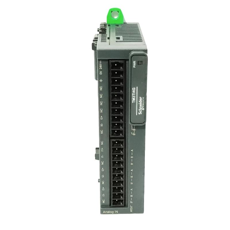
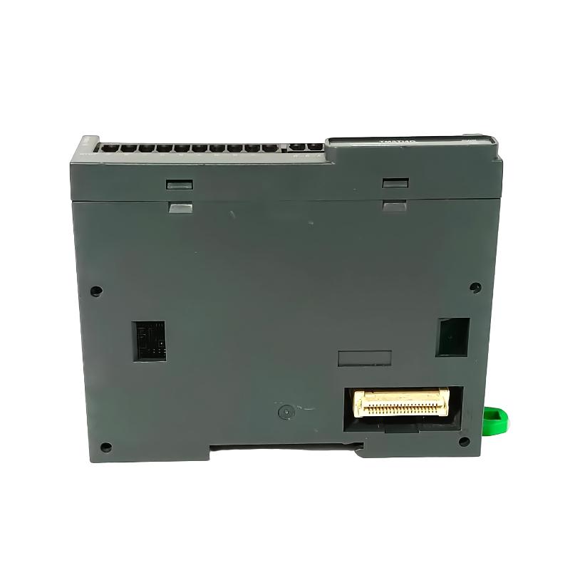
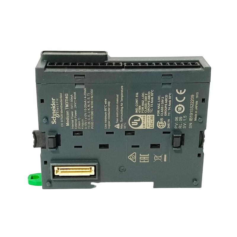
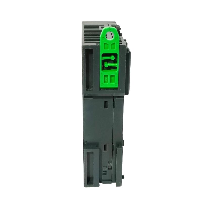
- Schneider
- TM3TI4G
- Analog Input Module
- France
- 90 × 70 × 23.6 mm
- 0.1 kg
- Xiamen, China
- New & In Stock
- T/T, PayPal, Western Union
- 1 Year
- 1-3 Working Days
- DHL, UPS, TNT, FedEx and EMS.
- 24-Hour Service
- COO
- 6
Our advantage

Global Logistics
We have a 10-year logistics and express cooperation agreement, so our products can be shipped to any place in the world.

Brand new and original
Our products are imported in bulk from the place of origin. Because of the cooperative relationship, our products are all original and 100% new.

24-hour service
We provide 7*24 hours service to our customers. We will be there whenever you need us.

Price advantage
All our products are priced very favorably because we have our own warehouse and supply.
| Company Information | |||
| [email protected] | |||
| Mobile | +8615980777398 | ||
| +8615980777398 | |||
| 15980777398 |
Product Overview
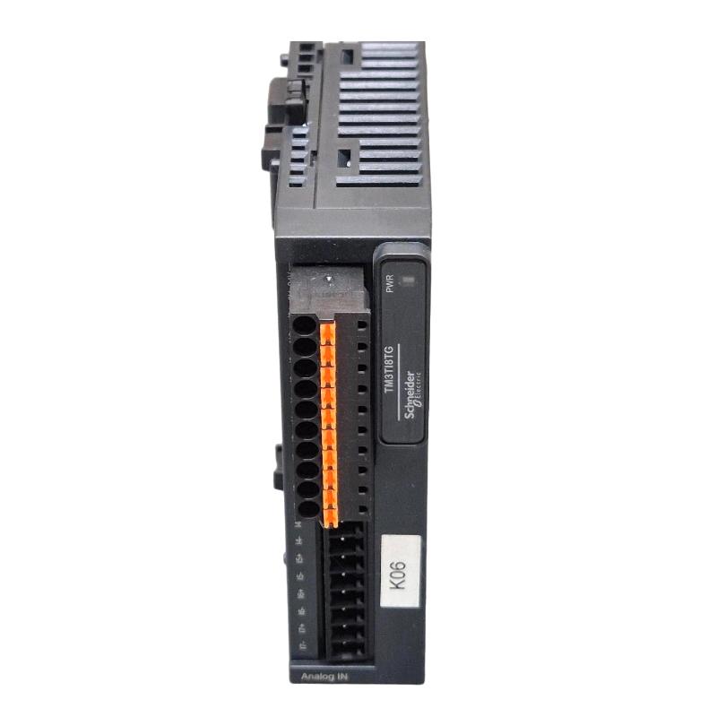
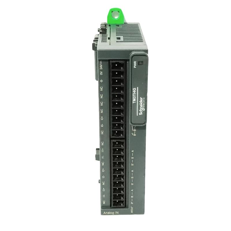
The Schneider TM3TI4G belongs to the Modicon TM3 expansion family and is identified as an analog input module for compatible PLC systems. It supports the acquisition of process signals so that a Modicon controller can use measured values in monitoring, alarm handling, and automated control sequences.
In industrial applications, analog input modules connect field instrumentation with the controller’s application program. Depending on the module’s documented input capabilities, these signals may represent process variables such as temperature, pressure, level, or other measured conditions. The PLC processes the acquired values and uses them alongside discrete inputs, timers, and programmed operating conditions to determine the next control action.
For engineers selecting or replacing the TM3TI4G, the exact model-specific input characteristics must be confirmed before wiring. Signal types, channel configuration, measurement ranges, resolution, and sensor compatibility determine whether the module suits the intended installation.
Technical Specifications
| Parameter | Description |
|---|---|
| Brand | Schneider Electric |
| Model | TM3TI4G |
| Product Series | Modicon TM3 |
| Product Type | Analog Input Module |
| Product Family | Modicon TM3 Expansion Modules |
| Primary Function | Analog signal acquisition |
| System Role | PLC process-input interface |
| Input Signal Types | Verify the supported signal types in the official TM3TI4G documentation |
| Input Channel Configuration | Confirm the channel arrangement in the model-specific datasheet |
| Measurement Range | Depends on the supported input type and configuration |
| Measurement Resolution | Refer to the official technical specifications |
| Conversion and Update Time | Refer to the manufacturer’s documentation |
| Sensor Compatibility | Confirm the supported sensors and signal characteristics before installation |
| Controller Compatibility | Verify using the Modicon TM3 system compatibility documentation |
| Mounting | Follow the manufacturer’s installation instructions |
| Wiring | Use the model-specific terminal assignment and wiring diagram |
| Dimensions | 90 × 70 × 23.6 mm |
| Weight | 0.1 kg |
Product Features
- Analog signal acquisition: Receives supported field signals and makes measurement data available to a compatible Modicon controller.
- PLC-based process monitoring: Allows measured values to be used in programmed operating sequences, alarm conditions, and process supervision.
- Modular system expansion: Adds input capability to a compatible controller arrangement without automatically requiring replacement of the base PLC.
- Instrumentation integration: Supports connection to appropriate field instrumentation when the signal type and electrical requirements match the module’s specifications.
- Channel-specific configuration: Requires each input to be configured according to the connected instrument and the intended measurement.
- Maintenance identification: The full model designation helps technicians distinguish the required module during equipment servicing and replacement planning.
Working Principle
The TM3TI4G operates as an input interface within a compatible Modicon TM3 control system. A field instrument produces a signal representing a measured process condition. The module receives the supported signal, processes it according to its hardware capabilities, and makes the resulting measurement data available to the PLC.
The controller then evaluates the acquired value within its application program. Depending on the process, the program may compare the value with configured limits, calculate a control response, generate an alarm, or advance an operating sequence. The resulting command can be sent through an appropriate output module or another control interface.
For example, a process skid may use an instrument to monitor a variable that affects a pump or valve sequence. The input module supplies the measurement to the controller, and the program checks whether the value remains within the permitted operating range. If the value crosses a configured threshold, the controller can initiate the programmed response.
Correct measurement depends on matching the field instrument to the module’s supported input characteristics. Incorrect wiring, unsuitable signal selection, poor grounding, or an incorrect channel configuration can result in invalid readings. The exact wiring and configuration procedure should follow the official documentation for the TM3TI4G.
Role in a Modicon TM3 PLC Control Architecture
| System Component | Role in the Control Architecture |
|---|---|
| Modicon Logic Controller | Executes the application program and processes acquired input values |
| TM3 Expansion Connection | Transfers input data between the module and the compatible controller |
| TM3TI4G Analog Input Module | Acquires supported analog signals from field instrumentation |
| Field Sensors and Transmitters | Measure process conditions and supply corresponding signals |
| Digital Input Modules | Provide discrete status information from switches and contacts |
| Digital Output Modules | Execute discrete control commands generated by the PLC |
| Analog Output Modules | Supply analog control signals where required by the application |
| Actuators and Final Control Elements | Respond to commands issued by the wider control system |
| Programming and Diagnostic Tools | Support channel configuration, monitoring, and fault diagnosis |
Industrial Applications
| Application | Typical Use |
|---|---|
| Process Skids | Acquires supported instrumentation signals for process monitoring and control |
| Water Treatment Equipment | Supplies compatible measurement signals for monitoring process conditions |
| Packaging Machinery | Provides process feedback for temperature, pressure, or other variables when supported by the input specification |
| Material Processing | Allows measured operating conditions to be incorporated into PLC logic |
| Industrial Test Equipment | Collects supported analog measurements during automated test sequences |
| Machine Automation | Adds measurement inputs where the control program needs more process feedback |
| Utility Systems | Interfaces compatible instrumentation with a PLC-based monitoring arrangement |
| Control Panel Upgrades | Extends input capacity in an existing Modicon TM3 installation after compatibility verification |
Installation and Maintenance
- Confirm the exact model. Verify the complete TM3TI4G designation against the installed equipment records and the manufacturer’s product documentation.
- Check controller compatibility. Confirm that the intended Modicon controller supports the module and that the planned expansion configuration meets system requirements.
- Isolate electrical power. Follow the site’s lockout/tagout procedure and verify that relevant circuits are in a safe state before handling the module or field wiring.
- Inspect the mounting arrangement. Ensure that the module is securely installed and that the cabinet environment meets the manufacturer’s requirements.
- Identify each field instrument. Record the sensor or transmitter type and determine whether its output signal is supported by the TM3TI4G.
- Review the official wiring diagram. Confirm terminal assignments, signal connections, reference terminals, and any shielding or grounding requirements.
- Inspect the wiring. Check conductor condition, terminal tightness, polarity where applicable, and separation from sources of electrical interference.
- Configure the input channels. Set each channel according to the supported input type and the requirements of the connected instrument.
- Check the expansion connection. Confirm that the module is correctly seated and that its connection to the controller or expansion system is secure.
- Validate measurement values. Compare readings with an appropriate reference instrument or known process condition and investigate unexpected deviations.
- Test the application response. Confirm that configured limits, alarms, and control sequences respond correctly to input changes under approved commissioning conditions.
- Document maintenance findings. Record sensor details, channel assignments, configuration changes, and test results. If readings are incorrect, inspect the instrument, wiring, configuration, and controller diagnostics before determining whether the module requires replacement.
Compatible System Components
| Component | Function in the System |
|---|---|
| Compatible Modicon Logic Controller | Processes acquired values and executes the control application |
| Modicon TM3 Digital Input Modules | Receive discrete field-status signals |
| Modicon TM3 Digital Output Modules | Execute discrete commands from the controller |
| Modicon TM3 Analog Output Modules | Supply analog command signals where supported |
| Compatible Field Sensors and Transmitters | Provide input signals accepted by the module |
| Terminal Blocks and Wiring Accessories | Organize field connections and simplify servicing |
| Control Power Supply | Supplies the relevant control-system circuits |
| Actuators and Final Control Elements | Carry out control actions commanded by the PLC |
| Programming and Diagnostic Tools | Support configuration, monitoring, and troubleshooting |
Recommended Related Models
| Model or Product Family | Product Type | Relationship |
|---|---|---|
| Schneider Modicon TM3 Analog Input Modules | Analog Input Modules | Provide alternative input configurations; verify signal compatibility before selection |
| Schneider Modicon TM3 Digital Input Modules | Discrete Input Modules | Add discrete feedback from switches and sensors |
| Schneider Modicon TM3 Digital Output Modules | Discrete Output Modules | Add discrete control outputs for machine functions |
| Schneider Modicon TM3 Analog Output Modules | Analog Output Modules | Provide analog commands for compatible control applications |
| Schneider Modicon TM3 Communication Modules | Communication Expansion Modules | Address supported communication requirements within the system configuration |
| Schneider Modicon Logic Controllers | Programmable Logic Controllers | Process input data and coordinate the overall control sequence |
Key Advantages
- Expanded measurement capability: Adds supported analog input functions to a compatible Modicon control system.
- PLC-integrated monitoring: Makes acquired process values available to the controller program for evaluation and response.
- Modular architecture: Supports incremental expansion of the control system.
- Instrumentation integration: Connects compatible field instruments with PLC-based process logic.
- Structured troubleshooting: Helps maintenance teams isolate faults by checking the instrument, wiring, channel configuration, and controller status.
Technical FAQs
1. What is the main function of the Schneider TM3TI4G?
The TM3TI4G is identified as a Modicon TM3 analog input module. Its role is to acquire supported field signals and make measurement information available to a compatible PLC. Confirm the exact input types and channel configuration using Schneider Electric’s official model-specific documentation.
2. Which sensors or transmitters can be connected to the TM3TI4G?
Compatibility depends on the input signal types supported by the specific module. Before connecting an instrument, check its output signal, electrical requirements, measurement range, and wiring arrangement against the official TM3TI4G specifications.
3. What can cause incorrect analog input readings?
Potential causes include an incompatible field instrument, incorrect wiring, loose terminals, electrical interference, improper grounding, or an incorrect channel configuration. Compare the reading with a suitable reference and check the instrument, wiring, and controller diagnostics systematically.
4. Can the TM3TI4G replace another Modicon TM3 analog input module?
Not automatically. Analog input modules may differ in supported signals, measurement ranges, channel arrangements, and configuration requirements. Compare the official datasheets and verify controller compatibility before choosing a substitute.