

ProductPRODUCT
Featured products
Contact Us
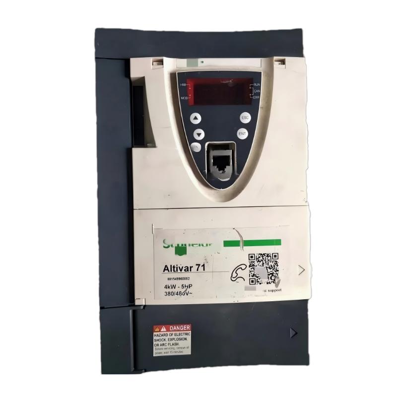
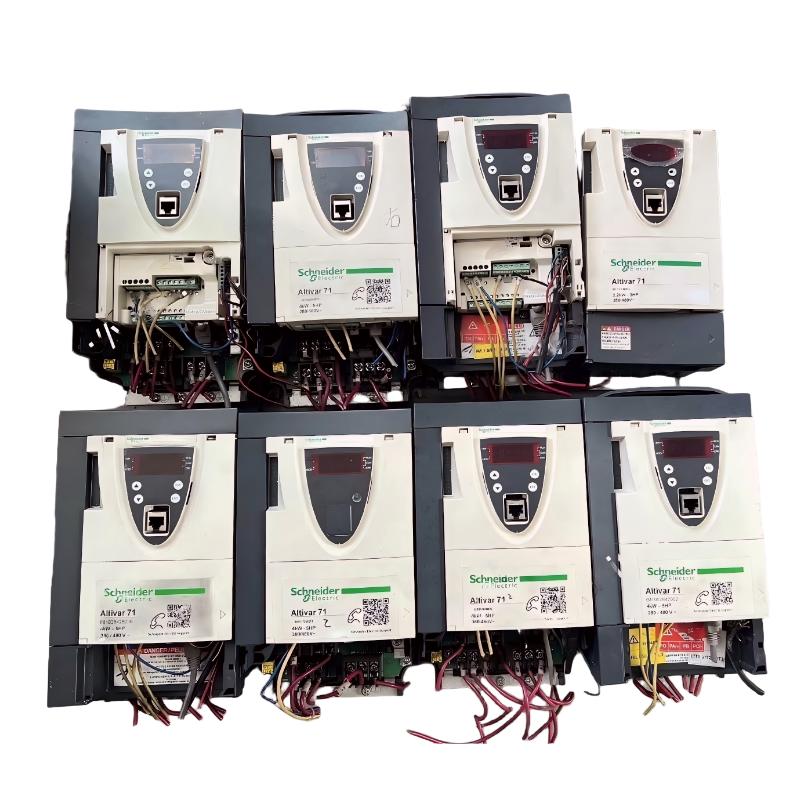
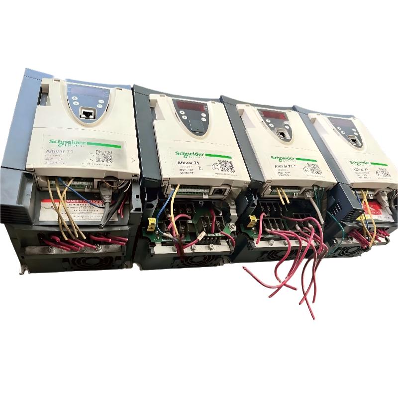
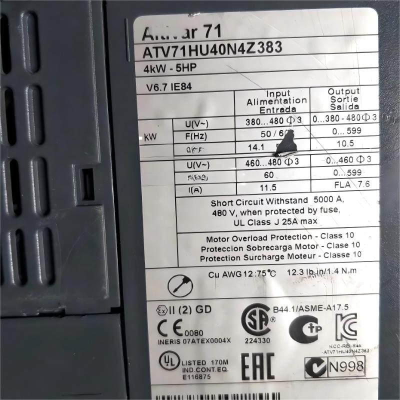
- Schneider
- ATV71HU40N4Z383
- Permanent Magnet Synchronous Motor
- France
- 260 x 187 x 155 mm
- 4 kg
- Xiamen, China
- New & In Stock
- T/T, PayPal, Western Union
- 1 Year
- 1-3 Working Days
- DHL, UPS, TNT, FedEx and EMS.
- 24-Hour Service
- COO
- 5
Our advantage

Global Logistics
We have a 10-year logistics and express cooperation agreement, so our products can be shipped to any place in the world.

Brand new and original
Our products are imported in bulk from the place of origin. Because of the cooperative relationship, our products are all original and 100% new.

24-hour service
We provide 7*24 hours service to our customers. We will be there whenever you need us.

Price advantage
All our products are priced very favorably because we have our own warehouse and supply.
| Company Information | |||
| [email protected] | |||
| Mobile | +8615980777398 | ||
| +8615980777398 | |||
| 15980777398 |
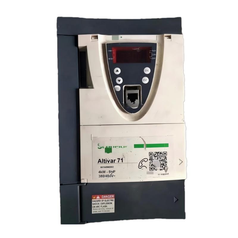
Product Overview
The Schneider ATV71HU40N4Z383 Permanent Magnet Synchronous Motor is an industrial motor component designed for controlled rotary motion and integration into automated motor-control systems. Permanent magnet synchronous motor technology uses permanent magnets within the rotor to establish the rotor magnetic field, allowing the motor to operate synchronously with the rotating magnetic field generated by the stator when correctly controlled.
In industrial automation, permanent magnet synchronous motors can be used where stable motor operation, controlled rotation, and efficient electromechanical energy conversion are required. The motor normally operates as part of a complete system that includes a compatible drive, control equipment, electrical protection, mechanical transmission, and the driven machine.
The ATV71HU40N4Z383 has user-provided dimensions of 260 × 187 × 155 mm and a listed weight of 4 kg. These physical parameters are important for equipment layout, installation planning, replacement preparation, and spare-parts management.
A typical automation architecture can be represented as:
Controller → Motor Drive → Permanent Magnet Synchronous Motor → Mechanical Load
Depending on the machine, additional feedback devices and sensors may be included to provide information required for motor control and machine monitoring.
Technical Specifications
| Parameter | Specification |
|---|---|
| Manufacturer | Schneider Electric |
| Model | ATV71HU40N4Z383 |
| Product Type | Permanent Magnet Synchronous Motor |
| Motor Technology | Permanent Magnet Synchronous Motor |
| Application | Industrial Motor Control and Automation |
| Dimensions | 260 × 187 × 155 mm |
| Weight | 4 kg |
| Installation | Industrial Machinery / Motor-Control System |
| Control Method | Compatible Electronic Motor Drive |
| Typical Application | Automated Machinery and Industrial Motion Systems |
Specific electrical and mechanical characteristics such as rated power, voltage, current, speed, torque, shaft configuration, feedback type, and thermal characteristics should be verified against the exact product identification and applicable technical documentation before installation or replacement.
What Is the Schneider ATV71HU40N4Z383?
The Schneider ATV71HU40N4Z383 is identified as a Permanent Magnet Synchronous Motor intended for integration into an industrial motor-control system.
A permanent magnet synchronous motor differs from a conventional induction motor because permanent magnets provide the rotor’s magnetic field. The stator generates a rotating magnetic field, and the rotor interacts with this field to produce controlled rotational movement.
A simplified operating system consists of:
Electrical Power → Motor Drive → ATV71HU40N4Z383 → Mechanical Load
In an automated machine, the complete control chain may include:
PLC / Motion Controller → Drive → Motor → Mechanical Transmission → Machine
This architecture allows motor movement to become part of a coordinated production or machine-control sequence.
Permanent Magnet Synchronous Motor Working Principle
The operation of a permanent magnet synchronous motor is based on the interaction between the magnetic fields of the stator and rotor.
Stator Magnetic Field
The stator contains electrical windings. When controlled electrical power is supplied, the windings generate a rotating magnetic field.
Permanent Magnet Rotor
Permanent magnets establish the rotor magnetic field without requiring the same type of electrical rotor excitation used in some other motor technologies.
Synchronous Operation
The rotor interacts with the rotating stator field and rotates synchronously under appropriate operating conditions.
Electronic Drive Control
For industrial automation, the motor operates together with a compatible electronic drive. The drive controls the electrical output supplied to the motor and coordinates motor operation with external commands.
This creates a complete electromechanical system capable of converting controlled electrical energy into mechanical rotation.
Role in Industrial Automation
The motor itself is only one element of an industrial motion-control system.
A typical architecture can be represented as:
Machine Sensors → PLC / Controller → Motor Drive → ATV71HU40N4Z383 → Mechanical Equipment
The controller determines the desired machine behavior, while the drive manages the electrical conditions required for motor operation.
Depending on the application, feedback equipment may provide additional information related to speed, position, or motor operating conditions.
This makes the motor suitable for automated systems requiring controlled rotary movement.
Industrial Applications
Permanent magnet synchronous motor technology can be incorporated into various industrial systems when the motor and drive are correctly matched.
Automated Manufacturing Machinery
Production machines often require controlled movement during different stages of the manufacturing cycle. A motor-drive combination can provide the required mechanical rotation.
Conveyor Systems
Conveyors may require controlled motor operation to coordinate material movement between different machine sections.
Material Handling
Automated material-handling equipment can use controlled rotary motion for transport, positioning, and mechanical movement.
Packaging Machinery
Packaging equipment can require synchronized motor movement for feeding, conveying, positioning, and other machine functions.
Industrial Processing Equipment
Process machinery may use electrically controlled motors to operate rotating equipment at controlled operating conditions.
Machine Automation
The motor can form part of an automated machine where motor movement must be coordinated with PLC logic, sensors, and other equipment.
Motor Drive Integration
A permanent magnet synchronous motor requires a suitable control system to operate correctly.
The associated motor drive can provide functions such as:
- Motor starting
- Motor stopping
- Speed regulation
- Torque control
- Acceleration
- Deceleration
- Fault monitoring
- Motor protection
- External control integration
A basic architecture is:
PLC / Controller → Motor Drive → ATV71HU40N4Z383
The controller establishes the required machine behavior, while the drive manages the motor’s electrical operation.
The exact drive selection and configuration must be verified against the motor’s actual electrical and feedback requirements.
PLC and HMI Integration
The motor can become part of a complete automated machine through its associated drive.
A typical system may include:
| Component | Typical Function |
|---|---|
| PLC / Motion Controller | Executes machine-control logic |
| HMI | Provides operator control and monitoring |
| Motor Drive | Controls motor operation |
| ATV71HU40N4Z383 | Produces mechanical rotation |
| Feedback Device | Provides applicable speed or position information |
| Mechanical Transmission | Transfers motor movement to the machine |
| Sensors | Monitor machine conditions |
| Safety System | Provides required safety functions |
The PLC can provide operating commands while the HMI can display status and diagnostic information supported by the overall system.
Installation Guidelines
The supplied dimensions for the ATV71HU40N4Z383 are:
260 × 187 × 155 mm
The listed weight is:
4 kg
These values should be considered when planning the motor installation and surrounding machine structure.
Mechanical Mounting
The mounting structure should be sufficiently rigid to support the motor and withstand normal operating loads.
Fasteners should be installed correctly and checked during maintenance.
Shaft Alignment
Correct shaft alignment is essential for rotating machinery.
Misalignment between the motor and driven equipment can contribute to:
- Increased vibration
- Coupling wear
- Bearing loading
- Mechanical noise
- Increased temperature
- Reduced service life
The motor should therefore be aligned according to the requirements of the mechanical system.
Cooling
Adequate cooling must be maintained during operation.
The motor should not be installed in an environment where surrounding equipment prevents appropriate heat dissipation.
Electrical Integration
The motor should be connected to a compatible drive according to the applicable electrical design.
Before startup, technicians should inspect:
- Motor power connections
- Protective grounding
- Drive configuration
- Feedback connections where applicable
- Cable condition
- Control signals
- Safety circuits
- Mechanical coupling
Power and control cables should be routed appropriately to minimize unwanted electromagnetic interference.
Commissioning Procedure
A structured commissioning procedure can help prevent installation and configuration problems.
Step 1: Verify Motor Identification
Confirm the complete product designation:
ATV71HU40N4Z383
Check the motor identification before connecting it to the drive.
Step 2: Inspect Mechanical Installation
Verify mounting, shaft alignment, coupling, fastening, and mechanical clearance.
Step 3: Verify Electrical Connections
Check motor cables, grounding, drive connections, and applicable feedback wiring.
Step 4: Configure the Drive
Enter verified motor information into the compatible drive.
Only actual motor data should be used.
Step 5: Perform a Controlled Start
Initially operate the motor under controlled conditions.
Check:
- Rotation direction
- Acceleration
- Deceleration
- Noise
- Vibration
- Temperature
- Drive status
Step 6: Test the Mechanical Load
After verifying motor operation, connect or operate the complete mechanical system according to the commissioning procedure.
Step 7: Verify Automation Control
If a PLC or motion controller is used, verify the complete command and feedback sequence.
Troubleshooting and Fault Diagnosis
Motor faults should be diagnosed together with the drive, control system, and mechanical load.
Motor Does Not Start
Possible causes include:
- No drive command
- Incorrect motor configuration
- Drive fault
- Incorrect wiring
- Active safety interlock
- Mechanical obstruction
- Control-system problem
The associated drive should be checked for status and fault information before assuming that the motor itself has failed.
Motor Rotates Incorrectly
Unexpected rotation can be associated with:
- Motor wiring
- Drive configuration
- Command configuration
- Control-system settings
The motor and drive configuration should be checked before further operation.
Excessive Vibration
Possible causes include:
- Shaft misalignment
- Loose mounting
- Coupling problems
- Bearing wear
- Mechanical imbalance
- Abnormal load
Mechanical inspection should be performed before replacing electrical components.
Excessive Temperature
High temperature may result from:
- Excessive load
- Insufficient cooling
- Abnormal operating conditions
- Mechanical problems
- Incorrect configuration
- Prolonged high-load operation
The motor, drive, load, and surrounding environment should be evaluated together.
Intermittent Operation
Possible causes include:
- Loose connections
- Feedback problems
- Drive faults
- Control instability
- Communication problems
- Thermal protection
- Mechanical conditions
Fault history and operating trends can help identify recurring problems.
Preventive Maintenance
Regular maintenance can help maintain reliable motor operation.
Mechanical Inspection
Inspect motor mounting, coupling, shaft alignment, and mechanical connections.
Vibration Monitoring
Unexpected changes in vibration can indicate mechanical problems that should be investigated.
Temperature Monitoring
Monitor motor temperature where appropriate and investigate abnormal changes.
Cable Inspection
Inspect power and feedback cables for damage, loose connections, insulation deterioration, and mechanical stress.
Drive Inspection
The associated drive should also be checked for faults, alarms, cooling conditions, and electrical connection problems.
Load Monitoring
Changes in mechanical load can influence motor temperature, operating current, vibration, and speed behavior.
Replacement Considerations
When replacing the ATV71HU40N4Z383, verify the complete product identification before installation.
Important considerations include:
- Full model number
- Motor technology
- Electrical characteristics
- Compatible drive
- Feedback configuration
- Mechanical mounting
- Shaft dimensions and coupling
- Motor cables
- Control architecture
- Machine requirements
The supplied dimensions are:
260 × 187 × 155 mm
The listed weight is:
4 kg
A motor with similar physical dimensions should not automatically be considered interchangeable. Electrical, mechanical, control, and feedback compatibility must all be confirmed.
Physical Dimensions and Handling
The ATV71HU40N4Z383 has user-provided dimensions of 260 × 187 × 155 mm and a listed weight of 4 kg.
These physical parameters are useful for:
- Machine layout
- Installation planning
- Replacement preparation
- Spare-parts inventory
- Transportation
- Maintenance planning
During handling, the motor should be protected against impact, moisture, contamination, and unnecessary stress on connectors or mechanical interfaces.
Compatible System Components
Depending on the application, the motor may form part of a system containing:
- Schneider Electric motor drives
- PLC controllers
- Motion controllers
- HMI panels
- Feedback devices
- Industrial sensors
- Safety controllers
- Mechanical couplings
- Gearboxes
- Conveyor equipment
- Automated machinery
- Industrial communication equipment
The exact system architecture depends on the machine requirements and the selected control equipment.
Related Schneider Electric Product Families
| Product Family | Product Type | General Role |
|---|---|---|
| Altivar 71 | Variable Speed Drive | Industrial motor control |
| Altivar 61 | Variable Speed Drive | Variable speed applications |
| Altivar Process ATV630 | Process Drive | Process and utility motor control |
| Altivar Process ATV650 | Process Drive | Industrial process applications |
| Altivar Process ATV930 | Advanced Drive | Industrial motor and process control |
These families should not be regarded as direct replacements for the ATV71HU40N4Z383 without verifying electrical, mechanical, control, and application compatibility.
Engineering Best Practices
Match Motor and Drive
The motor and drive should be selected and configured as a compatible combination.
Maintain Shaft Alignment
Correct alignment helps reduce vibration, bearing stress, coupling wear, and mechanical losses.
Protect Motor Cables
Motor and feedback cables should be installed in a manner appropriate for the complete drive system.
Maintain Suitable Cooling
The motor should operate in an environment that provides appropriate heat dissipation.
Monitor Operating Trends
Changes in temperature, vibration, current, speed behavior, or fault frequency can provide useful information about developing problems.
Investigate Repeated Faults
Repeated motor or drive faults should be investigated systematically instead of relying only on repeated resets.
Key Advantages
Permanent Magnet Synchronous Technology
The motor uses permanent magnets to establish the rotor magnetic field and supports synchronous motor operation under appropriate control conditions.
Controlled Industrial Motion
When paired with a compatible drive, the motor can provide controlled rotary movement for automated machinery.
Automation Integration
The motor can become part of PLC, HMI, sensor, drive, and machine-control architectures.
Flexible Industrial Applications
The technology can be applied to suitable manufacturing, material-handling, packaging, conveyor, and process machinery.
Compact Physical Design
The supplied 260 × 187 × 155 mm dimensions provide useful information for machine installation and replacement planning.
Manageable Weight
The listed 4 kg weight is useful for mechanical installation, handling, transportation, and spare-parts planning.
Technical FAQs
What is the Schneider ATV71HU40N4Z383?
The Schneider ATV71HU40N4Z383 is identified as a Permanent Magnet Synchronous Motor for industrial motor-control and automation applications.
What motor technology does it use?
It uses permanent magnet synchronous motor technology, in which permanent magnets establish the rotor magnetic field.
What are the dimensions of the ATV71HU40N4Z383?
The supplied dimensions are 260 × 187 × 155 mm.
What is the weight of the ATV71HU40N4Z383?
The supplied weight is 4 kg.
Does the motor need a compatible drive?
Yes. In an industrial automation application, the motor should be operated with a compatible motor drive configured for the motor’s electrical and control characteristics.
What applications can use this motor?
Potential applications include automated production machinery, conveyors, material-handling systems, packaging equipment, and other industrial machines requiring controlled rotary motion.
What should be checked before installation?
The motor model, electrical characteristics, compatible drive, mechanical mounting, shaft coupling, feedback configuration, cabling, and machine requirements should be verified.
What can cause excessive vibration?
Potential causes include mechanical misalignment, loose mounting, coupling problems, imbalance, bearing problems, or abnormal mechanical loading.
How should the motor be maintained?
Maintenance should include inspection of mechanical mounting, shaft alignment, coupling, cables, temperature, vibration, and the associated motor drive.
Conclusion
The Schneider ATV71HU40N4Z383 Permanent Magnet Synchronous Motor is an industrial motor component designed for integration into controlled motor and automation systems. Its permanent magnet rotor technology provides the magnetic field required for synchronous operation when combined with an appropriate control system.
The supplied physical specifications are 260 × 187 × 155 mm and 4 kg, providing important information for machine layout, installation, transportation, replacement, and spare-parts planning.
For reliable operation, the ATV71HU40N4Z383 should be correctly matched with its associated motor drive and mechanical load. Proper electrical integration, mechanical alignment, drive configuration, commissioning, thermal management, and preventive maintenance are essential for stable performance in industrial automation applications.