

ProductPRODUCT
Featured products
Contact Us
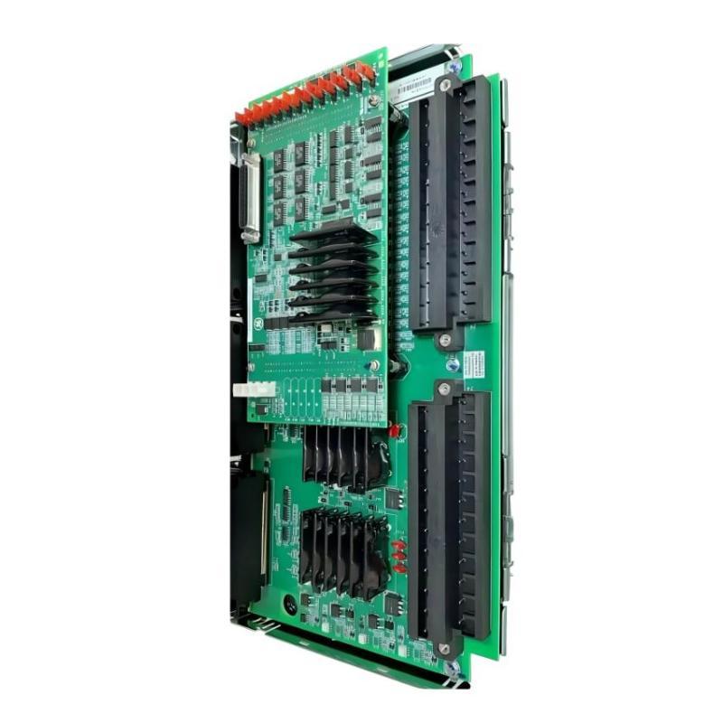
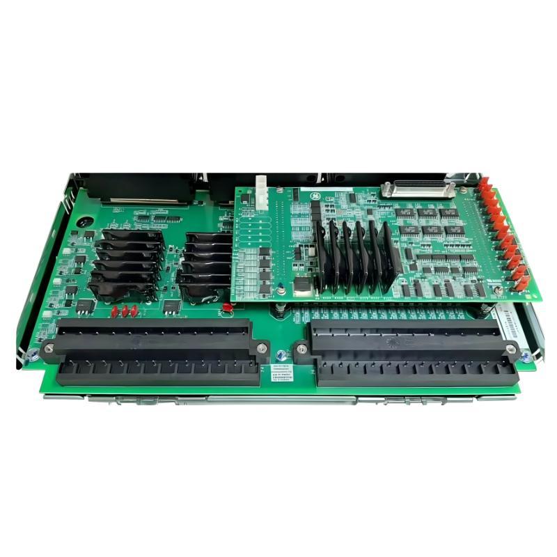
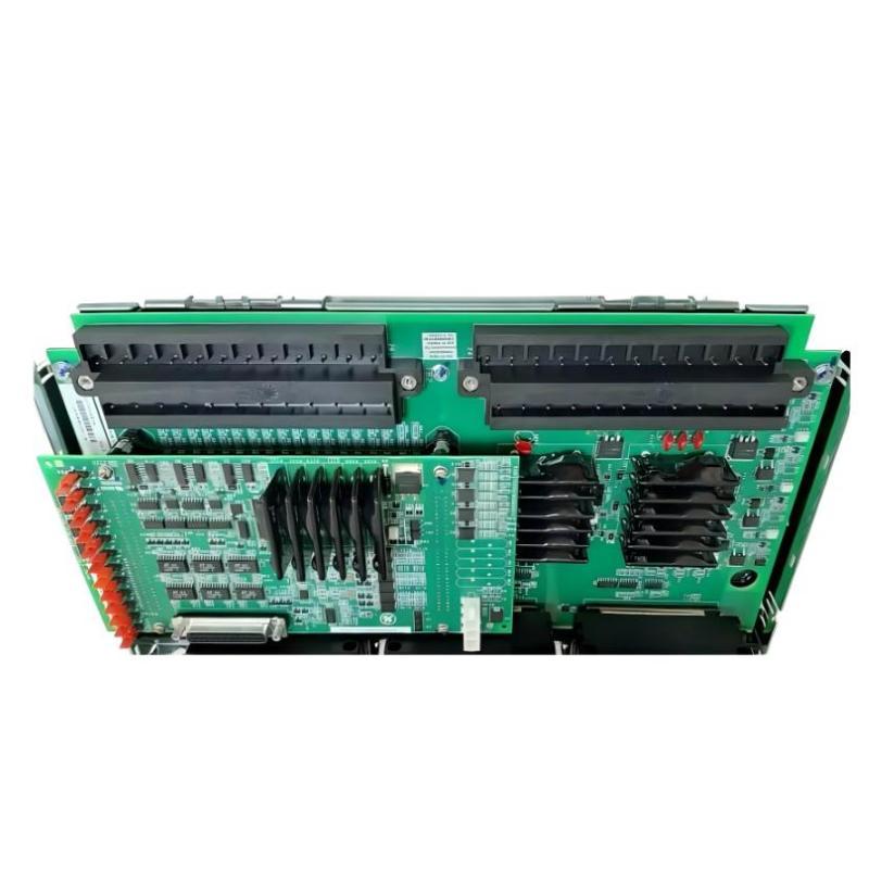
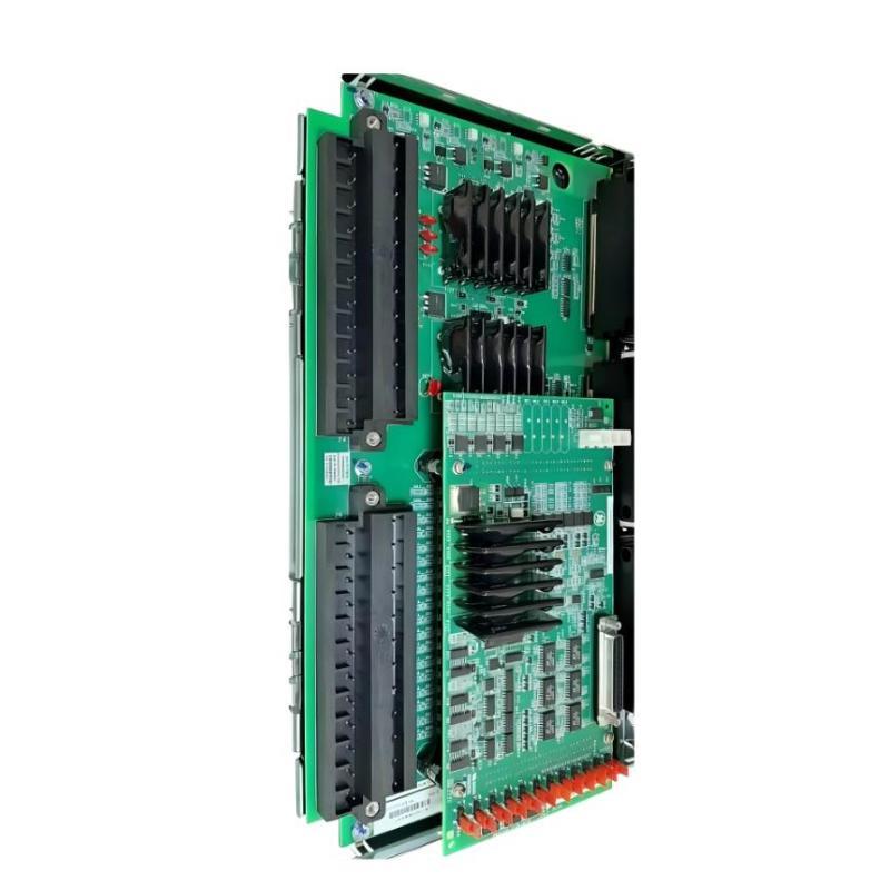
- GE
- IS210TREGH1B
- Trip DIN Rail Module
- USA
- 220 × 110 × 40 mm
- 0.42 kg
- Xiamen, China
- New & In Stock
- T/T, PayPal, Western Union
- 1 Year
- 1-3 Working Days
- DHL, UPS, TNT, FedEx and EMS.
- 24-Hour Service
- COO
- 5
Our advantage

Global Logistics
We have a 10-year logistics and express cooperation agreement, so our products can be shipped to any place in the world.

Brand new and original
Our products are imported in bulk from the place of origin. Because of the cooperative relationship, our products are all original and 100% new.

24-hour service
We provide 7*24 hours service to our customers. We will be there whenever you need us.

Price advantage
All our products are priced very favorably because we have our own warehouse and supply.
| Company Information | |||
| [email protected] | |||
| Mobile | +8615980777398 | ||
| +8615980777398 | |||
| 15980777398 |
Product Overview
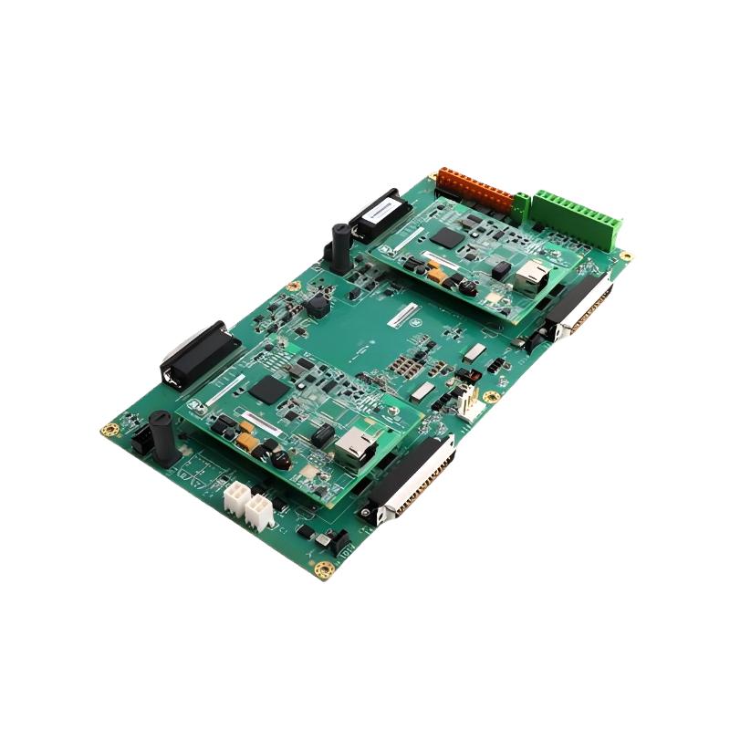
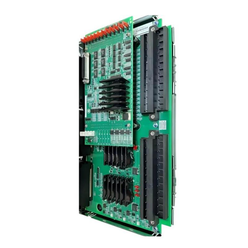
The GE IS210TREGH1B Trip DIN Rail Module is a specialized industrial control component designed for integration into GE control and automation systems. As part of the GE IS210 series, the module provides a compact DIN rail-mounted interface for trip-related control functions within an industrial control architecture.
Trip modules are commonly used in control systems where a defined protective or shutdown signal must be transferred between field devices, control logic, and associated equipment. By providing a dedicated interface within the control architecture, a trip module can contribute to equipment protection, process shutdown sequences, alarm handling, and system-level interlocking.
The GE IS210TREGH1B has listed dimensions of 220 × 110 × 40 mm and a weight of approximately 0.42 kg. Its DIN rail-oriented construction allows the module to be incorporated into electrical cabinets and control panels where organized, serviceable installation is required.
The module is particularly relevant to industrial applications where reliable trip signal management is part of the overall control and protection strategy.
Technical Specifications
| Parameter | Specification |
|---|---|
| Manufacturer | General Electric (GE) |
| Model | IS210TREGH1B |
| Product Type | Trip DIN Rail Module |
| Product Family | GE IS210 Series |
| Primary Function | Trip signal interface and control |
| Mounting Type | DIN Rail |
| Application | Industrial Control and Protection |
| Installation | Industrial Control Cabinet |
| Dimensions | 220 × 110 × 40 mm |
| Weight | 0.42 kg |
| Typical Use | Trip logic, shutdown interfaces, protective control systems |
| System Role | Control and protection interface |
Exact electrical characteristics, terminal assignments, signal levels, and system-specific operating parameters should be confirmed against the applicable hardware configuration before installation.
What Is the GE IS210TREGH1B?
The GE IS210TREGH1B is a DIN rail-mounted trip module intended for use within compatible GE industrial control systems.
The term trip generally refers to a control action that causes equipment or a process to move into a defined protective state. Depending on the system architecture, a trip command may be generated by a controller, protection device, monitoring system, or predefined interlock condition.
The module provides an interface within this control chain.
A simplified control sequence can be represented as:
Process Condition → Sensor / Protection Logic → Trip Decision → IS210TREGH1B → Control / Shutdown Equipment
The actual signal path depends on the host system and the equipment connected to the module.
Because trip functions can be associated with critical equipment protection, the exact application and wiring configuration should always be verified before commissioning.
Function and Working Principle
Trip Signal Interface
The primary role of a trip module is to participate in the transfer or management of a trip-related control signal.
When the associated control system determines that a defined trip condition exists, the trip signal can be processed through the relevant interface and transferred to the connected equipment.
This allows protective actions to become part of an organized industrial control sequence.
Protective Control Logic
A trip function may be associated with conditions such as abnormal operating parameters, equipment protection requirements, interlocking conditions, or emergency shutdown sequences.
The IS210TREGH1B forms part of the hardware interface supporting these control functions.
The exact logic remains dependent on the application, controller configuration, and connected equipment.
Signal Transfer
Industrial control systems frequently require signals to travel between different functional layers.
A typical arrangement may include:
- Field sensors
- Protection devices
- Control processors
- Interface modules
- Trip circuits
- Contactors or breakers
- Shutdown equipment
- Operator monitoring systems
The DIN rail module can provide an organized connection point within this architecture.
System Response
Once the relevant trip condition is detected and the control logic determines that a protective action is required, the associated trip circuit can initiate the configured response.
Depending on the application, the response may involve stopping equipment, opening a switching device, disabling a process, or activating another predefined protective sequence.
Role in Industrial Control Systems
The IS210TREGH1B can serve as an interface component between control logic and equipment protection functions.
In a large industrial automation system, different devices are responsible for sensing, processing, controlling, and protecting equipment. A trip interface helps connect these functional layers into a coordinated control architecture.
A simplified system structure is:
Field Equipment → Monitoring / Protection → Control Logic → Trip Interface → Protective Action
This architecture allows trip signals to be handled in an organized manner while keeping field wiring and cabinet-level interfaces structured.
The module can therefore contribute to:
- Equipment protection
- Shutdown control
- Interlocking
- Trip signal distribution
- Control-system integration
- Industrial cabinet organization
- Process safety-related control functions
The exact safety classification or protection capability of an installed system should not be assumed solely from the module model.
Industrial Applications
Turbine and Generator Systems
Industrial turbine and generator installations use multiple monitoring and protection functions to detect abnormal operating conditions.
A trip interface can form part of the control architecture responsible for transferring protective shutdown commands.
Power Generation Equipment
Power-generation systems frequently use coordinated control and protection circuits to prevent equipment damage during abnormal conditions.
DIN rail-mounted interface modules can help organize these circuits inside control cabinets.
Industrial Process Equipment
Large process plants may use trip functions to protect pumps, compressors, motors, drives, valves, and other equipment.
The IS210TREGH1B can be integrated into a compatible control architecture where a dedicated trip interface is required.
Compressor and Rotating Machinery Protection
Rotating machinery often relies on monitoring systems to identify abnormal conditions. When a configured limit or protection condition is reached, a trip command may be generated.
The trip interface provides part of the hardware path between the control system and the final protective action.
Automated Shutdown Systems
Industrial equipment may require automatic shutdown when predefined conditions occur. A trip module can support the corresponding signal interface within the control cabinet.
System Integration
The GE IS210TREGH1B should be considered as one component within a larger control architecture rather than as an independent control system.
A typical integration may include:
| System Layer | Example Function |
|---|---|
| Field Sensors | Detect process or equipment conditions |
| Protection System | Determines abnormal conditions |
| Controller | Executes configured control logic |
| IS210TREGH1B | Provides trip-related interface functionality |
| Switching Equipment | Performs the required protective action |
| HMI / SCADA | Displays status and alarms |
| Maintenance System | Supports diagnostics and service |
The exact arrangement depends on the host GE control platform and application requirements.
Before installation, technicians should confirm the module’s position in the system architecture and verify all associated wiring and interface requirements.
Installation Guidelines
Verify the Module Identification
Before installation or replacement, verify the complete identification:
- GE manufacturer designation
- IS210TREGH1B model number
- Board or module revision
- Existing cabinet position
- Connector arrangement
- Associated wiring
- Host control equipment
Similar GE modules may have different electrical functions even when their mechanical dimensions are comparable.
DIN Rail Mounting
The IS210TREGH1B is designed for DIN rail-oriented installation.
The mounting rail should be securely installed and capable of supporting the module and associated wiring. The module should be positioned so that terminals and connectors remain accessible for inspection and maintenance.
Cabinet Arrangement
A suitable cabinet layout should provide:
- Adequate physical clearance
- Accessible wiring
- Proper cable routing
- Separation from excessive heat sources
- Protection from excessive dust and moisture
- Clear identification of connected circuits
The listed module dimensions are 220 × 110 × 40 mm, which should be considered during cabinet layout and replacement planning.
Wiring
All field and control wiring should be connected according to the applicable system documentation.
Before energizing the system, technicians should verify:
- Terminal identification
- Wire routing
- Connector seating
- Signal polarity where applicable
- Grounding arrangements
- Interlock wiring
- Trip circuit continuity
Incorrect wiring in a trip circuit can result in unintended operation or failure to execute the intended protective response.
Commissioning Procedure
Commissioning should be performed systematically after installation.
Step 1: Visual Inspection
Inspect the module for:
- Physical damage
- Loose connectors
- Damaged terminals
- Contamination
- Mechanical mounting problems
Step 2: Verify Wiring
Compare installed wiring against the approved system documentation and cabinet drawings.
Step 3: Confirm Configuration
Verify the associated controller, protection logic, and trip configuration.
Step 4: Check Signal Paths
Confirm that the expected control and trip signals reach the correct interface points.
Step 5: Perform Functional Testing
Where permitted by the system’s maintenance procedure, test the applicable trip sequence under controlled conditions.
Step 6: Confirm Normal Operation
After testing, verify that the system has returned to its intended operating state and that no unexpected alarms or trip conditions remain active.
Troubleshooting the GE IS210TREGH1B
Trip Signal Not Detected
If an expected trip signal does not appear, inspect:
- Module connections
- Terminal wiring
- Associated protection device
- Controller logic
- Input or output signal path
- Connector condition
- Power or control circuit status
The problem may originate elsewhere in the control chain rather than in the module itself.
Unexpected Trip Condition
An unexpected trip should be investigated carefully before replacing the module.
Possible causes include:
- Incorrect control logic
- Faulty field signal
- Incorrect wiring
- Interlock activation
- Protection device operation
- Loose connection
- Configuration error
- External equipment fault
Trip circuits should not simply be bypassed to restore operation without understanding the cause of the trip.
Intermittent Trip Signal
Intermittent operation can be associated with:
- Loose terminals
- Vibration
- Cable damage
- Connector problems
- Electrical interference
- Unstable external signals
- Control-system communication problems
Physical inspection combined with system diagnostics can help isolate the source.
Module Appears Inactive
If the module does not appear to operate correctly, verify the complete system first.
Check:
- Module installation
- Cabinet wiring
- Associated power/control circuits
- Controller status
- Protection-system status
- Connectors and terminals
- Diagnostic information
Replacing the module should normally be considered only after external causes have been eliminated.
Preventive Maintenance
Regular inspection can help reduce unexpected control-system problems.
Inspect Mounting
Check that the module remains securely mounted to the DIN rail and that there is no mechanical movement.
Inspect Terminals
Look for loose, damaged, or contaminated terminals and connectors.
Check Wiring
Inspect cables for:
- Mechanical damage
- Excessive bending
- Loose connections
- Insulation deterioration
- Signs of overheating
Maintain Cabinet Conditions
The surrounding cabinet should be kept clean and protected from excessive dust, moisture, vibration, and temperature.
Review Trip Events
Where the host system provides event history, reviewing trip and alarm records can help identify recurring abnormal conditions.
Replacement Considerations
When replacing a GE IS210TREGH1B Trip DIN Rail Module, technicians should verify the complete part number rather than relying only on appearance or physical dimensions.
Important identification information includes:
- Full model number
- Revision
- Module markings
- Connector configuration
- Cabinet position
- Associated control equipment
- Existing wiring
- System configuration
The listed physical dimensions are 220 × 110 × 40 mm, and the listed weight is 0.42 kg.
The replacement module should be inspected for physical condition before installation. Connectors and mounting arrangements should also be compared with the existing installation.
After replacement, the applicable trip and interlock functions should be tested according to the site’s approved commissioning and maintenance procedures.
Physical Dimensions and Weight
The GE IS210TREGH1B has the following listed mechanical characteristics:
- Dimensions: 220 × 110 × 40 mm
- Weight: 0.42 kg
- Mounting: DIN rail
- Product Type: Trip DIN Rail Module
The compact 40 mm depth can be useful when designing or maintaining control cabinets with limited available space.
For replacement planning, technicians should also account for connector clearance and wiring space rather than considering the module body dimensions alone.
Compatible Control-System Components
Depending on the specific installation, the IS210TREGH1B may form part of a broader GE industrial control architecture containing:
- GE control processors
- Protection and monitoring devices
- Terminal boards
- Interface boards
- DIN rail assemblies
- Signal-conditioning components
- Relay or switching equipment
- Operator interfaces
- Industrial communication equipment
- Field instrumentation
The exact compatible hardware depends on the host system and engineering configuration.
A component should not be treated as a direct substitute merely because it belongs to the same GE IS210 family.
Engineering Best Practices
Several practices can improve reliability when working with the IS210TREGH1B.
Maintain Accurate Wiring Documentation
Control and trip circuits should be clearly documented so technicians can identify signal paths during commissioning and troubleshooting.
Keep Trip Circuits Clearly Identified
Trip-related wiring should be clearly labeled to reduce the possibility of incorrect maintenance intervention.
Avoid Uncontrolled Bypassing
Protective trip functions should not be bypassed without an approved engineering and maintenance procedure.
Check the Entire Signal Chain
When troubleshooting, examine the field device, protection logic, wiring, module, and final control equipment as one complete system.
Maintain Spare-Part Identification
Keeping the exact IS210TREGH1B identification in the maintenance inventory helps reduce the risk of installing an incompatible module during emergency repairs.
Key Advantages
DIN Rail Installation
The module is designed around a DIN rail-oriented form factor, supporting organized installation inside industrial control cabinets.
Compact Mechanical Design
With dimensions of 220 × 110 × 40 mm, the module can be incorporated into control panels where cabinet space must be managed carefully.
Dedicated Trip Interface
The IS210TREGH1B is intended for trip-related control and interface functions within compatible industrial systems.
Industrial Control Integration
The module can form part of a larger control and protection architecture connecting monitoring, control logic, and protective equipment.
Maintainable Cabinet Architecture
DIN rail installation can simplify physical organization, inspection, and replacement of control-system components.
Technical FAQs
What is the GE IS210TREGH1B?
The GE IS210TREGH1B is a Trip DIN Rail Module designed for integration into compatible GE industrial control and protection systems.
What is the primary function of the IS210TREGH1B?
Its primary role is to provide trip-related interface functionality within an industrial control architecture. The exact signal function depends on the host system and configuration.
What are the dimensions of the IS210TREGH1B?
The listed dimensions are 220 × 110 × 40 mm.
How much does the IS210TREGH1B weigh?
The listed weight is approximately 0.42 kg.
How is the IS210TREGH1B installed?
The module is designed for DIN rail mounting within an appropriate industrial control cabinet.
Can the IS210TREGH1B be used as a standalone controller?
No. It should be regarded as an interface component within a larger compatible industrial control architecture rather than a standalone PLC or general-purpose controller.
What can cause an IS210TREGH1B trip circuit problem?
Potential causes include incorrect wiring, faulty external protection devices, controller configuration problems, loose connections, damaged cables, interlock conditions, or issues elsewhere in the trip circuit.
Should another GE IS210 module be used as a replacement?
Not automatically. The complete model number, revision, electrical interface, connector arrangement, and host-system requirements should be verified before selecting a replacement.
What should be checked before replacing the module?
Technicians should verify the exact model number, revision, wiring, connectors, cabinet position, associated control equipment, and system configuration before replacement.
Conclusion
The GE IS210TREGH1B Trip DIN Rail Module is a compact industrial control component designed to support trip-related interface functions within compatible GE automation and protection architectures. Its role is to help connect control logic and protective actions within an organized industrial control system.
With listed dimensions of 220 × 110 × 40 mm and a weight of 0.42 kg, the module is suitable for DIN rail-based control cabinet installations where organized wiring, accessible maintenance, and efficient use of cabinet space are important.
Reliable operation depends on correct system integration, accurate wiring, proper DIN rail installation, suitable cabinet conditions, and verification of the complete trip signal path. For replacement or maintenance work, the full GE IS210TREGH1B identification should always be confirmed before installation, and the associated trip and interlock functions should be tested according to the applicable system procedures.