

ProductPRODUCT
Featured products
Contact Us
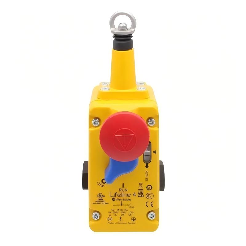
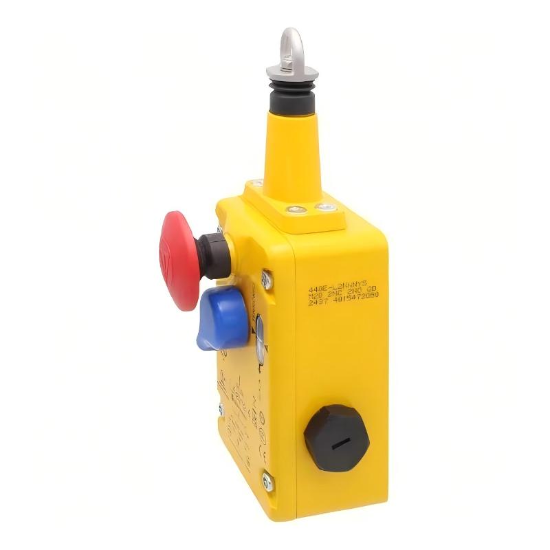
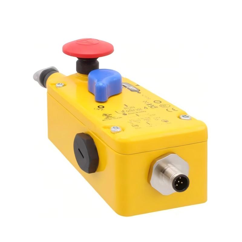
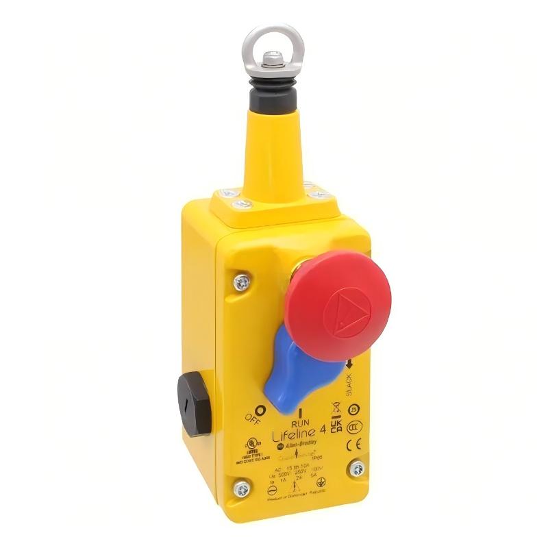
- Allen Bradley
- 440E-L2NNNYS
- Cable Pull Switch
- USA
- 196 × 48 × 85 mm
- 0.8 kg
- Xiamen, China
- New & In Stock
- T/T, PayPal, Western Union
- 1 Year
- 1-3 Working Days
- DHL, UPS, TNT, FedEx and EMS.
- 24-Hour Service
- COO
- 4
Our advantage

Global Logistics
We have a 10-year logistics and express cooperation agreement, so our products can be shipped to any place in the world.

Brand new and original
Our products are imported in bulk from the place of origin. Because of the cooperative relationship, our products are all original and 100% new.

24-hour service
We provide 7*24 hours service to our customers. We will be there whenever you need us.

Price advantage
All our products are priced very favorably because we have our own warehouse and supply.
| Company Information | |||
| [email protected] | |||
| Mobile | +8615980777398 | ||
| +8615980777398 | |||
| 15980777398 |
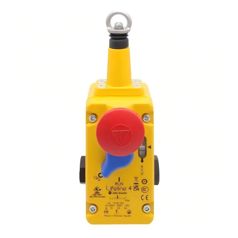
Product Overview
The Allen Bradley 440E-L2NNNYS Guardmaster Lifeline 4 Cable Pull Switch is a cable-operated safety switch for emergency-stop applications on conveyors, production machinery, and extended equipment. It allows an operator to initiate a machine stop by pulling a cable installed along the protected area.
The Lifeline 4 is suited to applications where emergency-stop access is required along a machine rather than at one fixed pushbutton location. A properly installed cable can extend along the operating area, giving personnel multiple points from which the emergency-stop function can be activated.
The switch is installed as part of the machine safety circuit and works with the associated safety relay, safety controller, contactors, or other safety-related control equipment. Its practical role is to detect a change in cable condition and provide the corresponding switching signal to the safety system.
Technical Specifications
| Parameter | Value |
|---|---|
| Manufacturer | Allen Bradley |
| Model / Part Number | 440E-L2NNNYS |
| Product Type | Guardmaster Lifeline 4 Cable Pull Switch |
| Series | Guardmaster Lifeline 4 |
| Application | Emergency stop and cable-pull safety monitoring |
| Dimensions | 196 × 48 × 85 mm |
| Weight | 0.8 kg |
Product Features
- Guardmaster Lifeline 4 cable pull safety switch for industrial machinery.
- Provides emergency-stop access along conveyors and extended machine sections.
- Uses a tensioned cable as the operator interface for emergency stopping.
- Suitable for distributed emergency-stop arrangements.
- Detects cable actuation through a mechanical switching mechanism.
- Can be incorporated into a safety relay or safety controller circuit.
- Suitable for conveyor systems, material handling equipment, and production machinery.
- Provides a field-mounted interface between the emergency-stop cable and machine safety circuit.
Working Principle
The 440E-L2NNNYS operates through a mechanically tensioned safety cable connected to the Lifeline 4 switching mechanism. During normal operation, the cable and switch mechanism remain in their intended operating condition.
When the cable is pulled, the mechanical mechanism changes the state of the safety contacts. The connected safety control equipment detects this change and can initiate the configured machine stop function.
The operating sequence can be represented as:
Emergency-Stop Cable → Lifeline 4 Switch → Safety Input → Safety Relay / Safety Controller → Machine Stop Function
The cable arrangement must be installed and tensioned correctly so that the switch can respond to an emergency pull and maintain the intended monitoring function. After activation, the machine should remain in the required stopped condition until the cause has been investigated and the safety system has been reset according to the machine’s safety procedure.
Role in a Machine Safety Control Architecture
The Lifeline 4 serves as a field-level switching device in a machine safety circuit. It converts a physical cable-pull action into a safety-related switching signal that can be evaluated by downstream safety equipment.
Safety Cable → 440E-L2NNNYS → Safety Relay / Safety Controller → Output Switching Device → Machine Stop
| System Element | Function |
|---|---|
| Emergency-Stop Cable | Provides an accessible emergency-stop interface along the machine |
| 440E-L2NNNYS | Detects cable activation and changes the safety switching state |
| Safety Relay / Safety Controller | Evaluates the safety input and manages the safety response |
| Contactors / Drive Safety Interface | Carries out the required machine stopping action |
| Standard PLC | Can monitor machine status and safety-system feedback where appropriate |
| HMI | Displays machine and safety status for operators and maintenance personnel |
| Machine Equipment | Enters the defined safe state following the safety stop command |
The Lifeline 4 should be evaluated as part of the complete safety function rather than as an independent safety system. The final safety performance depends on the complete circuit architecture, connected devices, installation, validation, and machine risk assessment.
Industrial Applications
| Application | Typical Use |
|---|---|
| Conveyor Systems | Emergency stopping along long conveyor sections |
| Material Handling | Providing distributed emergency-stop access around handling equipment |
| Production Lines | Allowing operators to stop machinery from multiple positions |
| Packaging Machinery | Emergency intervention along extended machine sections |
| Bulk Material Transport | Cable-operated emergency stopping on conveying equipment |
| Assembly Equipment | Providing an accessible emergency-stop interface around production stations |
| Industrial Processing Systems | Monitoring cable activation around extended processing equipment |
Installation and Maintenance
- Select an accessible mounting position
Install the switch where the emergency-stop cable can be reached and operated from the intended working area. - Plan the cable route before installation
Ensure the cable follows the protected machine section without unnecessary bends, obstructions, or interference with moving equipment. - Maintain the specified cable condition
Install and tension the cable according to the applicable manufacturer requirements and machine safety design. - Secure the cable supports
Check that eye bolts, support points, and other cable hardware remain firmly attached to the machine structure. - Inspect the switch mechanism
Make sure the actuator and cable connection move freely and are not obstructed by dirt, mechanical components, or damaged hardware. - Verify electrical connections
Check the safety contact wiring against the machine electrical drawings before commissioning. - Test cable activation
Pull the cable from representative positions along the installation and confirm that the safety circuit responds correctly. - Check the reset function
Confirm that activation does not result in an unintended restart and that the required reset procedure operates as intended. - Inspect the cable periodically
Look for corrosion, fraying, deformation, excessive slack, or other conditions that could affect operation. - Check the complete safety circuit
Verify that switch activation produces the intended machine response through the connected safety relay, controller, or other safety equipment. - Keep the switch clean
Prevent accumulated dust, process residue, and other contaminants from interfering with the mechanical operating mechanism. - Document functional testing
Record inspection and safety-function tests according to the maintenance schedule and machine safety procedures.
Compatible System Components
| Component | Role in the System |
|---|---|
| Allen Bradley Guardmaster Safety Relays | Evaluate safety-switch signals and control safety outputs |
| Allen Bradley Safety Controllers | Process safety inputs and coordinate machine safety functions |
| Allen Bradley Safety I/O Modules | Provide safety-rated field interfaces |
| Allen Bradley Contactors | Disconnect or control machine power as required by the safety design |
| Allen Bradley PowerFlex Drives | Can participate in machine stopping architectures where the selected drive and safety configuration support the required function |
| Emergency-Stop Circuit Components | Complete the safety circuit associated with the cable pull switch |
| Conveyor Control Equipment | Coordinates normal machine operation with the emergency-stop function |
Recommended Related Models
| Model | Product Type | Typical Relationship |
|---|---|---|
| Allen Bradley 440E-D2NNNYS | Guardmaster Lifeline 3 Cable Pull Switch | Related Lifeline cable pull safety switch |
| Allen Bradley 440E-L13041 | Guardmaster Lifeline Cable Pull Switch | Related cable-operated safety switch |
| Allen Bradley 440E-L13141 | Guardmaster Lifeline Cable Pull Switch | Related Lifeline safety switch configuration |
| Allen Bradley 440E-L22041 | Guardmaster Lifeline Cable Pull Switch | Related cable pull safety device |
| Allen Bradley 440K Series | Guardmaster Safety Interlock Switch | Used for machine guard monitoring |
| Allen Bradley 440R Series | Guardmaster Safety Relay | Used for safety signal evaluation |
Key Advantages
- Provides emergency-stop access along extended machinery and conveyor systems.
- Converts a cable-pull action into a switching signal for the machine safety circuit.
- Suitable for distributed emergency-stop arrangements.
- Can be integrated with Guardmaster safety relays and safety controllers.
- Provides a practical field-level safety interface for industrial equipment.
- Supports routine functional testing of the emergency-stop cable system.
Technical FAQs
Where is the Guardmaster Lifeline 4 typically used?
It is commonly applied to conveyors, production lines, material-handling systems, and other extended machinery where personnel need emergency-stop access from multiple positions.
What happens when the cable connected to the 440E-L2NNNYS is pulled?
The cable movement actuates the switch mechanism and changes the safety contact state. The connected safety system can then process the signal and initiate the configured machine stop function.
Why must the cable be installed and tensioned correctly?
Cable position and tension directly affect the mechanical operation of the switch. Incorrect installation can make the emergency-stop function difficult to operate or prevent the system from detecting the intended cable condition correctly.
Can the 440E-L2NNNYS be used as a standalone safety system?
The switch is a field component of a larger machine safety function. It normally works together with suitable safety control equipment and the machine’s stopping devices. The complete safety circuit must be designed, validated, and maintained according to the application’s safety requirements.